


I. INTRODUCTION
Microstrip antennas have been extensively studied and investigated during the past three decades. It is because of their low-profile characteristics such as light weight, low volume, and low cost, they are used for several applications such as military, space, as well as for commercial applications. The recent developments in the field of wireless communications have increased the need for multiband microstrip antennas. The necessities of present day communication systems have also prompted an increased demand for low cost and more compact antennas. The advantage of the multiband antennas is to be able to integrate several frequency bands on one single antenna, making it useful for various applications. For the purpose of a flexible reciprocal orientation between the transmitting and receiving antennas, circular polarization (CP) is also becoming more attractive. In view of these perspectives, compact circularly polarized antennas with multiband operations will be more useful for wireless systems.
Lin et al. have proposed a conservative triple-band microstrip slot antenna connected to WLAN/Wi-MAX applications [Reference Lin, Lei, Xie, Ning and Fan1]. It is simply made out of a substrate; a microstrip feed line, and a ground plane on which some basic slots are carved. Compact printed slot antenna with three linearly polarized bands covering global positioning system (GPS), global system for mobile communication (GSM), and Bluetooth is attempted by Bod et al. [Reference Bod, Hassani and Samadi Taheri2]. The antenna consists of an octagonal-shaped slot attached with three inverted U-shaped strips at upper part of the substrate. The feeding is arranged at the bottom side of the substrate with beveled stepped rectangular patch. A novel asymmetric M-shaped patch for dual and triple bands is designed by Lin et al. [Reference Lin, Ruan and Wu3]. However, all these antennas [Reference Lin, Lei, Xie, Ning and Fan1–Reference Lin, Ruan and Wu3] are of linearly polarized radiation. However, to eliminate the multipath effect and to make the data reception independent of the orientation of the handheld device, multiband CP antennas are required.
A stacked microstrip antenna with asymmetrical U-slot patches for dual-band CP is nominated by Payam et al. [Reference Payam, Lee, Elsherbeni and Fan4]. Two orthogonal modes for CP at dual band are obtained by introducing properly optimized U-slots with unequal slot lengths on the square patches. Dual-band single-feed circularly polarized aperture coupled microstrip antenna is proposed by Nasimuddin et al. [Reference Nasimuddin and Chen5]. For dual-band operation, an S-shaped slot is cut at the center of the square patch. By adjusting the S-shaped slot arm lengths, two resonating frequency bands can be obtained with good CP. A novel design employing the multi-stacked patches and fed with a single coaxial probe is studied by Falade et al. for GPS receivers [Reference Falade, Rehman, Yue, Chen and Parini6]. Three asymmetrical patches are introduced on the three stacked layers for the triple band CP emission. Triple band antennas have been demonstrated using H-shape [Reference Chang and Kiang7], hexagonal slot with slits [Reference Baek and Hwang8], and dual annular-shaped [Reference Wang, Guo and Sheng9] slot patch structures. Several coplanar waveguide [Reference Rezaeieh and Kartal10, Reference Chen and Yung11] and multi-layered stacked [Reference Anguera, Ortigosa, Puente, Borja and Soler12, Reference Wang and Hu13] patch structures are proposed for triband CP operation. However, most of these antennas [Reference Payam, Lee, Elsherbeni and Fan4–Reference Wang and Hu13] are based on stacked patch technique to generate multiband CP emission, so the fabrication becomes complex with increase in stacked layers. Single probe feed, single layer triple band antennas with slits on the patch [Reference Fujimoto and Tagawa14] and ground plane are available in the literature [Reference Abdelsayed, Shams and Allam15]. Although these structures generate CP at three bands, the generated 3 dB CP bandwidths of all these approaches are very narrow (<1%). So, the design of single probe feed, single layer triple band CP antennas using fractal boundary antennas is examined in this paper.
Fractal concept has been successfully applied so far to design compact and multiband antennas. However, boundary fractals are applied to patch structures only for designing compact antennas. Here, asymmetrical fractal boundary curves applied along the boundaries of square patch for CP radiation. Later, a 45° rotated asymmetrical fractal slot is embedded at the center of the patch for multiband CP operation. The dimensions of the fractal curves and probe feed location are optimized to design triple band CP antennas with good performance.
II. ANTENNA GEOMETRY
The generation process of the Minkowski fractal boundary curve is shown in Fig. 1. The design of half-circled fractal curve is depicted in Fig. 2. In case of Minkowski curve, the indentation factor (IF) is indentation depth D, whereas it is indentation radius (R) for half-circled fractal curve. The side and top views of the proposed Minkowski fractal boundary antenna is pictured in Fig. 3.
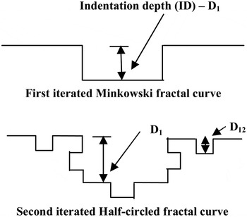
Fig. 1. The generation process of Minkowski fractal curve.
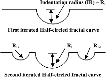
Fig. 2. The generation process of half-circled fractal curve.
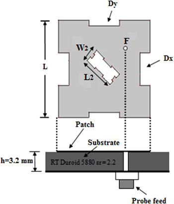
Fig. 3. The top side views of the proposed Minkowski triband CP antenna.
The proposed antennas design procedure is given below in three steps:
-
(1) The presented fractal boundary circularly polarized antenna can be obtained by replacing each straight line on four sides of a square patch with a first iterated fractal curve having different IFs, but keeping the IF same for opposite sides [Reference Reddy and Sarma16]. Here, the end-to-end length of the patch is considered as L = 36 mm to resonate first frequency band at 2.4 GHz.
-
(2) Afterwards, a 45° rotated fractal slot is inserted in the middle of the patch with dimensions W 2 = 0.15×L and L 2 = 0.35×L and considering the feed point at (7 mm, 7 mm), triple band CP operation is achieved. The inserted asymmetrical fractal slot is a scaled version of the main fractal patch. The dimensions of the fractal slot are chosen in such a way that it resonates at 5.8 GHz frequency. Without any embedded fractal slot, antenna resonates at only frequency band 2.4 GHz, whereas with slot antenna resonates at multiband.
-
(3) Later, for good CP radiation at generated three bands, the IFs of the fractal curves and feed point location are optimized using high frequency structural simulator electromagnetic simulator optimetric analysis setup.
III. SIMULATION RESULTS
All the proposed antennas are implemented over an RT/Duroid substrate 5880 of thickness 3.2 mm, dielectric constant 2.2, and loss tangent 0.0019. To observe the triband CP radiation physically, the simulated surface current distributions on the fractal patch structure is pictured in Fig. 4. The first band at 2.4 GHz is excited due to strong current distribution along outer fractal boundary curves and inner fractal slot. The second band at 3.4 GHz is mainly generated because of the current distribution along the only outer fractal boundary curves. The scaled fractal slot at the center is mainly responsible for 5.8 GHz frequency band. Asymmetrical fractal curves are used as boundaries of the patch and slot to generate the two orthogonal modes with equal amplitude and 90° out of phase for circularly polarized radiation at all the three frequency bands. The active current distribution area is responsible for radiation and it becomes smaller at higher resonating frequencies, which leads to the lowering of antenna gain at 3.4 and 5.8 GHz. The gain of the antenna is directly proportional to the electrical area of the patch.
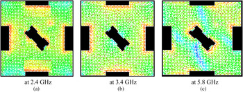
Fig. 4. The simulated current distributions on the triband fractal patch. (a) at 2.4 GHz, (b) at 3.4 GHz, and (c) at 5.8 GHz.
Three different fractal boundary antennas have been examined. The first antenna is based on the Minkowski fractal patch. The second antenna is implemented by employing half-circled fractal curves. Later, by using Minkowski and half-circled fractal curves as boundaries of square patch along x- and y-axes, respectively, poly fractal boundary antenna is designed. In each case, iteration order (IO) one and two antennas are analyzed.
A) Minkowski fractal boundary CP antennas
The indentation depths (IDs) of the Minkowski curve along x- and y-axes (D x , Dy ) controls the radiation characteristics. With symmetrical fractal curves (D x = D y ), the antenna generates linear polarization. The CP radiation from symmetric patch can be obtained by using different IDs along the x- and y-axes (D x ≠ D y ). The proposed Minkowski antennas are pictured in Fig. 5. The first five antennas are based on IO one, whereas sixth one is IO two antenna. The simulated return loss, axial ratio, and gain plots of Minkowski antennas are pictured in Figs 6–8. It is observed that with increase of indentation depths of the fractal curves, the return loss, and axial ratio curves are shifted toward left. It is due to increase in the electrical length of the patch with the increase in indentation depth. The summarized simulation results are given in Table 1.
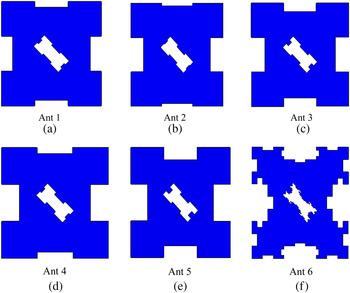
Fig. 5. The proposed Minkowski triband CP patch structures for various IDs. (a) Ant 1. (b) Ant 2. (c) Ant 3. (d) Ant 4. (e) Ant 5. (f) Ant 6.
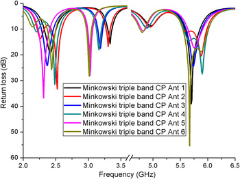
Fig. 6. The simulated return loss curves of Minkowski antennas.
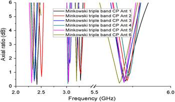
Fig. 7. The simulated axial ratio plots of Minkowski antennas.
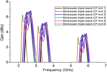
Fig. 8. The simulated gain plots of Minkowski antennas.
Table 1. The summarized simulation results of Minkowski antennas.
B) Half-circled fractal boundary CP antennas
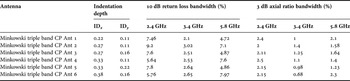
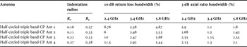
The IRs of the half-circled fractal curves along x-and y-directions of a patch are responsible for radiation properties of the antenna. If fractal curves of same IRs (R x = R y ) are used as boundaries of a patch, then linear polarization radiation is generated. Fractal curves with different IRs (R x ≠ R y ) along two orthogonal directions are used for CP radiation. The proposed triband half-circled antennas with inserted fractal slot for triband CP radiation are pictured in Fig. 9. The simulated return loss, axial ratio, and gain plots of half-circled antennas are given in Figs 10–12. The summarized simulation results are tabled in Table 2.
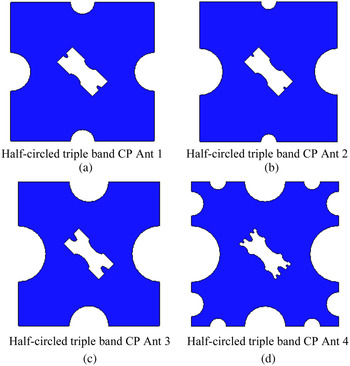
Fig. 9. The proposed half-circled triple band CP antennas. (a) Half-circled triple band CP Ant 1. (b) Half-circled triple band CP Ant 2. (c) Half-circled triple band CP Ant 3. (d) Half-circled triple band CP Ant 4.
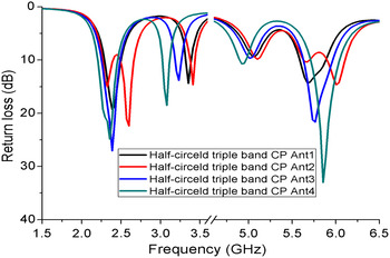
Fig. 10. The simulated return loss curves of half-circled antennas.
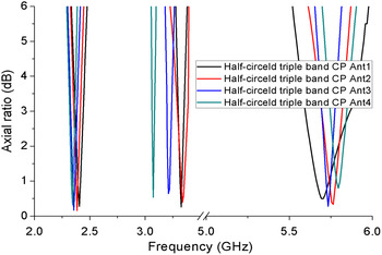
Fig. 11. The simulated axial ratio curves of half-circled antennas.
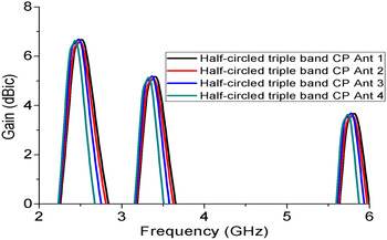
Fig. 12. The simulated gain curves of half-circled antennas.
Table 2. The summarized simulation results of half-circled antennas.
C) Poly fractal boundary CP antennas
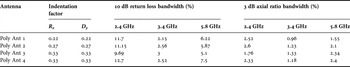
In the earlier sections, same fractal curve with different IFs is used as boundary to the square patch to generate perturbation in the structure for CP radiation. Here, two different fractal curves are used as edges of square patch to design poly fractal boundary structures for triband CP radiation. The half-circled fractal curve is deployed along the x-axis, whereas Minkowski is employed along the y-axis. A scaled and 45° rotated poly fractal slot is embedded at the center for triband CP emission. By varying the IFs of the fractal curves, several poly fractal boundary antennas are designed and depicted in Fig. 13. The simulated return loss, axial ratio, and gain characteristics of poly fractal antennas are pictured in Figs 14–16, respectively. The summarized simulation results are tabulated in Table 3.
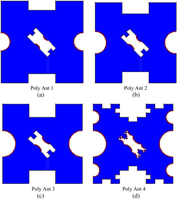
Fig. 13. The proposed poly triple band CP antennas. (a) Poly Ant 1. (b) Poly Ant 2. (c) Poly Ant 3. (d) Poly Ant 4.
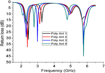
Fig. 14. The simulated return loss curves of poly antennas.
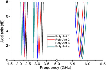
Fig. 15. The simulated axial ratio characteristics of poly antennas.
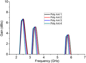
Fig. 16. The simulated gain characteristics of poly antennas.
Table 3. The summarized simulation results of poly antennas.
IV. MEASURED RESULTS AND DISCUSSION
To validate the proposed design and simulation results, the studied Minkowski triband CP Ant 1 patch is fabricated on RTduroid 5880 substrate of volume 50 × 50 × 3.2 mm3 and the measurements are carried out. The fabricated antenna mounted in standard anechoic chamber is pictured in Fig. 17. The fabricated antenna under test is kept stationary and a standard antenna such as horn (linearly polarized) is rotated at a speed of 30 revolutions per minute with the help of rotating mechanism in the anechoic chamber. The antenna radiation and rotating linear patterns are measured in two orthogonal planes. The rotating linear pattern is known as axial ratio pattern. The axial ratio values at different frequencies are extracted from the rotating linear pattern. The corresponding comparisons of simulated and measured results are presented in Figs 18–20. The achieved 3 dB axial ratio bandwidths at tribands 2.4, 3.4, and 5.8 GHz are 2.3% (2376–2427 MHz), 1% (3383–3417 MHz), and 1.8% (5750–5850 MHz), respectively. The measured gain indicates that the presented antenna generates a gain of more than 2 dBi over operating frequency bands. The measured radiation patterns in horizontal and vertical planes are pictured in Fig. 21. Due to smaller electrical length of the antenna at 5.8 GHz when compared with the other two resonating frequencies, unwanted nulls are observed in the radiation pattern as shown in Fig. 21(c). The rotating linear pattern of the fabricated antenna at 2.4 GHz is depicted in Fig. 22. The generated 3 dB axial ratio beamwidth of the proposed antenna is ±45°. Here, the proposed antenna is implemented over a single layer and simple probe is used for feeding purpose. By using different fractal curves and increasing the IO, more compact antennas can be designed.
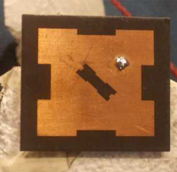
Fig. 17. Prototype of fabricated antennas.
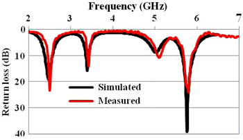
Fig. 18. Comparison of simulated and measured return loss results.
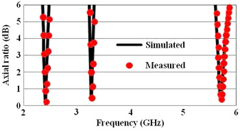
Fig. 19. Comparison of simulated and measured axial ratio results.
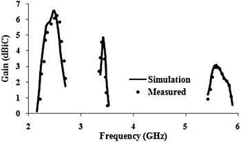
Fig. 20. Comparison of simulated and measured gain results.
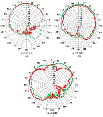
Fig. 21. The measured horizontal and vertical plane radiation patterns of fabricated antenna at tribands. (a) at 2.4 GHz, (b) at 3.4 GHz, (c) at 5.8 GHz.
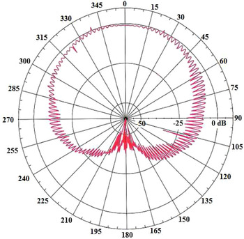
Fig. 22. The rotating linear pattern of the fabricated antenna at 2.4 GHz.
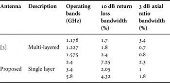
From the measured axial ratio plots, it is observed that the best axial ratio values close to 0 dB are obtained at the three resonance frequencies. It is an indication of CP radiation at the center frequencies. The proposed antennas are generating more than 2 dBi gain at all the operating frequency bands. A close agreement between the simulated and measured results is observed. The proposed antennas generated better triband CP radiation with single layer when compared with stacked layered CP antenna and it is given in Table 4.
Table 4. Comparison of the proposed antenna with literature.
V. CONCLUSION
This paper presents the design of fractal boundary microstrip antennas for triband CP radiation. An asymmetrical fractal slot is inserted in the fractal patch for triband CP operation. By varying the IF and IO of fractal curves, several triband antennas are proposed. The proposed antenna is fabricated and experimentally studied. A good agreement between the simulation and measured results is obtained. The suggested single layer, single probe feed multiband CP slot antenna is easy to fabricate and cost effective when compared with the multi-layered antennas existing in the open literature.
 V.V. Reddy received his B.Tech. degree (2008) in Electronics and Communication Engineering from Aurora's Engineering College affiliated to Jawaharlal Nehru Technological University, Hyderabad, India. He received M.Tech. degree in Advanced Communication Systems from National Institute of Technology, Warangal, India. Later, he continued his research work in the same institute. Presently, he is working as an Assistant Professor in the Department of Electronics and Communication Engineering, KITS, Warangal. His field of study includes microstrip fractal antennas and other areas of interest are antenna wave propagation. He has publications in 12 International journals and conferences.
 N.V.S.N. Sarma obtained his Bachelors degree with specialization in Electronics and Communications Engineering from College of Engineering, Kakinada, Jawaharlal Nehru Technological University in the year 1984. His Master's and Doctoral degrees are from the Indian Institute of Technology, Kharagapur, India in the year 1985 and 1992, respectively. He worked at Tata Institute of Fundamental Research, Mumbai for a short period from February 86 to July 87. He has been with the department of Electronics and Communications Engineering at National Institute of Technology, Warangal, India at various positions since 1990. About 70 papers are to his credit in International and National journals and conferences. His area of interest includes numerical electromagnetics, adaptive antenna arrays, and energy efficient routing protocols in wireless sensor networks.


