


1 Introduction
The transport of species in to/out of liquid drops exposed to another stream has wide application in many branches of science and engineering (Clift, Grace & Weber Reference Clift, Grace and Weber1978; Wong & Lin Reference Wong and Lin1992; Jahne & Haubecker Reference Jahne and Haubecker1998; Bryden & Brenner Reference Bryden and Brenner1999; Sirignano Reference Sirignano1999; Pompano et al. Reference Pompano, Liu, Du and Ismagilov2011). While a persistent interfacial gradient enables slower diffusive solute or heat transfer, the knowledge of fluid dynamics in a drop becomes crucial, as the generated convective inner flow (Bryden & Brenner Reference Bryden and Brenner1999) pattern and thereby the actual transport process can be greatly manipulated through small changes of local physics. Moreover, the imposed variable peripheral shear stress on a drop is responsible for inducing dominant convective/chaotic inner circulations (Stone, Nadim & Strogatz Reference Stone, Nadim and Strogatz1991; Bryden & Brenner Reference Bryden and Brenner1999; Sirignano Reference Sirignano1999; Elperin et al. Reference Elperin, Fominykh, Krasovitov and Lushnikov2013) that actively redirect/enhance species transport. Accordingly droplet-based microfluidics has gained special attention, as it offers rapid mixing, reduced dispersion and minimized surface fouling.
Recent studies (Kinoshita et al. Reference Kinoshita, Kaneda, Fujii and Oshima2007; Yoshitake et al. Reference Yoshitake, Yasumatsu, Nakaso and Fukai2010) indicate that heat/mass transfer in a drop or slug can be organized via suitably paired convective circulations, as they accelerate mixing in a direction transverse to the main flow. Tice et al. (Reference Tice, Song, Lyon and Ismagilov2003) noted that paired circulations in a drop lead to fairly non-uniform local reagent accumulation in a very short time. In experimental work the authors characterized the active role of the paired circulations as the twirling effect that reorientates/changes the internal flow direction and redistributes the entrained mass. For reagents placed on the path of a recirculation, the mixing governed by such a convective mechanism becomes more efficient. In contrast, if reagents are placed off the flow path, the diffusion controls the resulting slow mixing. However, an in-depth understanding of the governing convective mechanism and physics that actually facilitate the desired/enhanced species transport in both laminar and chaotic states (Bryden & Brenner Reference Bryden and Brenner1999; Tice et al. Reference Tice, Song, Lyon and Ismagilov2003; Yoshitake et al. Reference Yoshitake, Yasumatsu, Nakaso and Fukai2010) is still lacking. In addition, shear driven convective motions that are generated by paired circulations in/around suspended drops (Dong & Sau Reference Dong and Sau2018) play a crucial role in electrohydrodynamic phase separation processes (Baygents, Rivette & Stone Reference Baygents, Rivette and Stone1998) via drop–drop coalescence or breakup, in the dewatering of crude oil (Vigo & Ristenpart Reference Vigo and Ristenpart2010), in enhancing heat/mass transfer (Ogata & Yabe Reference Ogata and Yabe1993) and in fuel atomization (Xie et al. Reference Xie, Lim, Phua, Hua and Wang2006; Li et al. Reference Li, Jain, Ma and Nandakumar2015; Dong & Sau Reference Dong and Sau2019).
For liquid drops positioned in proximity in an external air stream, the imposed non-uniform interfacial shear stress significantly alters the inner dynamics by virtue of introduced new vortical entities and/or resultant flow bifurcation. The created spontaneous convective motion has sustainable impacts on heat/mass transport (Sirignano Reference Sirignano1999), air-pollution scavenging (Chen Reference Chen2001; Chen & Lu Reference Chen and Lu2003; Elperin, Fominykh & Krasovitov Reference Elperin, Fominykh and Krasovitov2009; Elperin et al. Reference Elperin, Fominykh, Krasovitov and Lushnikov2013), spray combustion (Sirignano Reference Sirignano1983; Tal, Lee & Sirignano Reference Tal, Lee and Sirignano1983) and fluid mixing (Stroock et al. Reference Stroock, Dertinger, Ajdari, Mezic, Stone and Whitesides2002). In early studies, a variety of theoretical models and correlations were obtained to quantify mass absorption and to predict the approximate role of the internal circulations based on Reynolds number ( $Re$) and/or drop diameter. Using the Hadamard (Reference Hadamard1911) model for internal circulation, Kronig & Brink (Reference Kronig and Brink1950) examined mass transfer for a falling liquid drop, which yielded a solute extraction rate 2.5 times higher compared to a stationary drop. However, the Hadamard solution is valid (Clift et al. Reference Clift, Grace and Weber1978) for conditions that support creeping flow (
 $Re\ll 1$) in small drops (diameter
  ${<}1.0$ mm). The experiments by Altwicker & Lindhjem (Reference Altwicker and Lindhjem1988) show that, for larger drops (diameter
  ${>}1.8$ mm), the derived mass transfer rate obtained by the Kronig & Brink model becomes lower than the experimental observation, as drops start showing oscillatory/unsteady flow behaviour. On the other hand, for turbulent inner flow conditions, Handlos & Baron (Reference Handlos and Baron1957) theoretically and experimentally examined mass transfer from a freely falling liquid drop into a second liquid phase, and claimed that diffusion alone is not the true driving force that transfers mass. Handlos & Baron’s study also indicates the possibility of active interfacial resistance and vital internal activity in the drop, though the physical details were not resolved. Later, Angelo, Lightfoot & Howard (Reference Angelo, Lightfoot and Howard1966) proposed a theoretical model for examining the impact of drop oscillation on mass absorption. Meanwhile, numerous experiments have been carried out (Kaji, Hishinuma & Kuroda Reference Kaji, Hishinuma and Kuroda1985; Altwicker & Lindhjem Reference Altwicker and Lindhjem1988) that expose the inherent limitations of the early theoretical models, and are devoted to accurate prediction of mass transfer rate for varied circumstances.
The discrepancy among theoretical models and experimental correlations for mass transfer has only lately been realized to originate primarily from the assumed incorrect dynamic behaviour of flows in a drop. Researchers accordingly opted for numerically solving the essentially nonlinear Navier–Stokes equations to unfold the precise two-phase hydrodynamic effects and resultant transport phenomena. Among early predictions, Hamielec & Johnson (Reference Hamielec and Johnson1962) theoretically revealed an internal streamline pattern in a drop using the steady Navier–Stokes equations ( $Re<80$). Later, Watada, Hamielec & Johnson (Reference Watada, Hamielec and Johnson1970) numerically studied the forced convection mass transfer in a single drop. In addition, Leclair et al. (Reference Leclair, Hamielec, Pruppacher and Hall1972) theoretically and experimentally investigated the nature of internal circulations in a falling water drop in air and reported that the creeping flow analysis greatly underestimates the strength of the inner velocity, whereas inviscid flow analysis overestimates it. However, due to the measurement constraints, only the crude development of a secondary inner vortex was predicted in a drop. Note that, in previous studies, greater emphasis has been made to quantify species transfer in drops via a variety of correlations. The focus has lately shifted to identifying the crucial convective inner flow phenomenon that the generated vortices can support and analysing the related performance, for designing efficient/targeted mass-transport devices.
Recently, efforts have been made to understand the precise physical mechanism that controls the entrainment of soluble gaseous toxins in a single liquid drop immersed in a contaminated outer air stream (Amokrane & Caussade Reference Amokrane and Caussade1999; Chen Reference Chen2001; Chen & Lu Reference Chen and Lu2003; Elperin et al. Reference Elperin, Fominykh and Krasovitov2009; Ubal et al. Reference Ubal, Harrison, Grassia and Korchinsky2010; Wylock, Colinet & Haut Reference Wylock, Colinet and Haut2012; Grassia & Ubal Reference Grassia and Ubal2018), especially for axisymmetric condition. A close look at existing investigations (Rivkind & Ryskin Reference Rivkind and Ryskin1976; Sundararajan & Ayyaswamy Reference Sundararajan and Ayyaswamy1984; Dandy & Leal Reference Dandy and Leal1989) implies that the imposed variable interfacial shear stress may promote breakup of the well-known Hill’s vortex (Clift et al. Reference Clift, Grace and Weber1978) and thereby substantially change the inner dynamics for drop pairs that are stationed in proximity; this has the potential to transform diffusive heat/mass transfer (Wong & Lin Reference Wong and Lin1992) to a dominantly convective mode (Bryden & Brenner Reference Bryden and Brenner1999). Studies by Sundararajan & Ayyaswamy (Reference Sundararajan and Ayyaswamy1984), Kaneda et al. (Reference Kaneda, Hyakuta, Takao, Ishizuka and Fukai2008) and Yoshitake et al. (Reference Yoshitake, Yasumatsu, Nakaso and Fukai2010) show that an augmented convective transport is realizable via locally strengthened Marangoni flow acceleration and/or rapid concentration buildup. In this way, interfacial reversal plus the occurrence of intermediate shear stress minima can facilitate the crucial bifurcation of Hill’s type primary vortex driven inner flow and create physically significant secondary vortices. Nevertheless, much of the existing literature mostly discusses diffusion-based transport properties, whereas significantly fewer studies have focused on exploring the potentially realistic issue of nonlinearity induced global enhancement (Bryden & Brenner Reference Bryden and Brenner1999; Tice et al. Reference Tice, Song, Lyon and Ismagilov2003) of heat/mass transfer and engendered inner convective mechanism that are quickly transformed to asymmetric/three-dimensional (3-D) (Bajer & Moffatt Reference Bajer and Moffatt1990) for small variation of control parameters.
As elaborated below, the convective flow mechanism that is created via the counter-rotating dynamics of the main stream driven primary (Hill’s) vortex ring and reversed flow/shear stress induced secondary vortex ring effectively entrains the gaseous outer  $\text{SO}_{2}$ into the side-by-side homogeneous or heterogeneous spherical water drop pair along the 3-D topological separation line for a large range of Reynolds number
  $Re$ and gap ratio
  $G/R$ (with
  $G$ the interfacial gap, and
  $R$ the drop radius). The created spontaneous convective mechanism actively regulates both interfacial mass entrainment rate as well as spreading of inner
  $\text{SO}_{2}$ until saturation is reached. The presence of such a convective process in drops and its impact on heat transfer are visible in the work of Sirignano (Reference Sirignano1983) and Tal et al. (Reference Tal, Lee and Sirignano1983), although the issue remained unresolved. Moreover Stone et al. (Reference Stone, Nadim and Strogatz1991) discussed realizable circumstances of chaotic flow generation in a buoyant drop in steady Stokes flow. Jana & Ottino (Reference Jana and Ottino1992) showed the substantial increase of heat transmission rate in a cavity flow, for conditions in which chaotic behaviour is present, notwithstanding the fact that net heat transfer exhibits a strong dependence on Péclet number
  $Pe$. The chaotic flow behaviour in a spherical drop has also been studied by Bajer & Moffatt (Reference Bajer and Moffatt1990). Later, for a non-neutrally buoyant spherical drop translating in an immiscible simple shear flow, Bryden & Brenner (Reference Bryden and Brenner1999) detected a significant boost of solute extraction rate by virtue of the created chaotic internal flow. Note that the convective dynamics is activated in other situations also, such as for nanoparticles suspended in droplets that induce Brownian-type motion (Johnson & Narayanan Reference Johnson and Narayanan1999; Prasher Reference Prasher2005; Mandal & Bakshi Reference Mandal and Bakshi2012) and interfacial temperature and concentration gradient induced Marangoni flows (Tice et al. Reference Tice, Song, Lyon and Ismagilov2003; Gunther, Jhunjhunwala & Thalmann Reference Gunther, Jhunjhunwala and Thalmann2005; Girard et al. Reference Girard, Antoni, Faure and Steinchen2006), which enhance species transfer by advection. Moreover, inflow paired vortex dynamics-led mass transport and boost of mixing are predicted for jet flows (Zaman Reference Zaman1996; Stroock et al. Reference Stroock, Dertinger, Ajdari, Mezic, Stone and Whitesides2002; Sau Reference Sau2004; Alkislar, Krothapalli & Butler Reference Alkislar, Krothapalli and Butler2007; Sau Reference Sau2011), although the exploration for drops (Dong & Sau Reference Dong and Sau2018) remained limited.
For species transfer involving a single liquid drop (Sundararajan & Ayyaswamy Reference Sundararajan and Ayyaswamy1984; Amokrane & Caussade Reference Amokrane and Caussade1999; Sirignano Reference Sirignano1999; Chen Reference Chen2001; Chen & Lu Reference Chen and Lu2003; Elperin et al. Reference Elperin, Fominykh and Krasovitov2009; Ubal et al. Reference Ubal, Harrison, Grassia and Korchinsky2010; Wylock et al. Reference Wylock, Colinet and Haut2012), the authors largely presumed that the physical process is driven by diffusion. This continued even when convective inner circulations looked sufficiently strong and Reynolds number seemed exceedingly large. Moreover, there exists no systematic study that shows how the convective mechanism actually is initiated in drops and dictates the species transport. In addition, the actual convective mass-transport process in drops exposed to a uniform stream is difficult to realize from the available (Bryden & Brenner Reference Bryden and Brenner1999) isolated case of simple shear induced chaotic flow state. The objective of the current work is therefore to address this fundamental issue for a pair of side-by-side spherical water drops, since multiple droplet forms are frequently encountered in nature that promote convective mass transport for  $Re\geqslant 30$.
Meanwhile, the encountered ‘blockage effect’ and ‘nozzle effect’ substantially alter the inner convective motion by virtue of the outer stream-imposed non-uniform interfacial shear stress on a drop and skewed topological flow separation. The blockage effect is activated as the downstream-moving air approaches the constricted neck region of two drops placed side-by-side, which results in the diversion of part of the oncoming air flow towards the free-stream-facing sides, making it move with a locally higher interfacial velocity gradient. However, on approach to a narrow neck, the air flow through the gap is also locally accelerated due to the so-called nozzle effect that helps to maintain the local mass conservation. Such interfacial air velocity variation/acceleration acts to significantly influence the paired convective vortical motion in a drop, and thereby the inner solute transport. Note that the heat transfer and inner hydrodynamics ( $Re\leqslant 150$) for side-by-side liquid spheres that were examined by Kim, Elghobashi & Sirignano (Reference Kim, Elghobashi and Sirignano1993) show the existence of distinct secondary vortices in the liquid drop’s stern regions; however, the influence of the resultant convective mechanism has not been explored. Similarly, the heat transfer for slurry drops has been studied by Bhatia & Sirignano (Reference Bhatia and Sirignano1993) and Sirignano (Reference Sirignano1999) for
  $Re\leqslant 300$, and here again the effect of internal convective circulations remained unexplored.
Moreover, under assumed axisymmetric flow conditions, Chen & Lu (Reference Chen and Lu2003) studied the two-dimensional (2-D) diffusion-dominated  $\text{SO}_{2}$ transfer from the gaseous outer stream into a heterogeneous water drop for
  $Re\leqslant 1$. The paired convective circulation-regulated solute entrainment that starts to dominate at moderate
  $Re$ has remained practically unidentified. In reality, for heterogeneous water drops (with a solid core) positioned in proximity in a contaminated outer stream, the convective solute transport in the liquid annulus is hindered by the presence of the solid nucleus, as there appear inevitable core size dependent topological shifts for the inner flow. In the present work, our focus is to unravel the dominant convective
  $\text{SO}_{2}$ transport mechanisms and governing physics for side-by-side positioned homogeneous and heterogeneous water drop pairs using varied separation gap (
 $G/R$), Reynolds number (
 $Re$) and solid fraction (
 $S$). These have remained largely unexplored, and are expected to offer a broad new understanding.

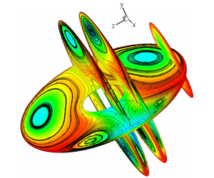
Figure 1. (a) Schematic of the flow configuration used to simulate  $\text{SO}_{2}$ transport in two side-by-side spherical water drops. For the upper drop, the computed
  $\text{SO}_{2}$ intrusion is shown at
  $t=0.002~\text{s}$,
  $G/R=0.5$ and
  $Re=150$. (b1,b2) Comparison of the present lift force
  $C_{l}$ and drag force
  $C_{d}$ with the results of Kim et al. (Reference Kim, Elghobashi and Sirignano1993) for varied gap ratio
  $G/R$ at
  $Re=100$ (
 $R$ is the drop radius). (c1,c2) Computed symmetry plane (
 $z=0$) flow behaviour in pure and heterogeneous water drops (
 $R_{s}/R=0.5$;
  $R_{s}$ is the radius of the solid core) reveals excellent agreement with the 2-D results of Chen & Lu (Reference Chen and Lu2003) for
  $Re=1$. The adopted domain lengths are:
  $L1=50R$,
  $L2=18R$,
  $L3=16R$ and
  $L4=19R$.
The paper has been organized as follows. In § 2 the physical problem and relevant assumptions are outlined; § 3 elaborates the governing equations, boundary conditions and the numerical procedure. Then §§ 4.1 and 4.2 describe the flow physics and solute transport for two pure water micro-drops, as  $Re$ is varied; while § 4.3 examines the influence of the separation gap
  $G/R$, and § 4.4 elucidates the convective
  $\text{SO}_{2}$ transfer mechanisms for heterogeneous drop pairs. Finally, § 5 offers concluding remarks.
2 The physical problem and assumptions
Gaseous  $\text{SO}_{2}$ transport in a pair of side-by-side homogeneous and heterogeneous spherical water drops is studied via 3-D simulations to unfold the dominant advective mechanism and physics. In nature, drops experience hydrodynamic drag and therefore deceleration relative to a cross-flow. Additionally, the presence of another drop in the vicinity (figure 1a) creates a varying impact on physical
  $\text{SO}_{2}$ intrusion as well as near-field flow, depending on Reynolds number
  $Re$ (defined by reference velocity
  $u_{g,\infty }$ and drop diameter
  $2R$) and gap ratio
  $G/R$ (surface-to-surface distance divided by drop radius), via the blockage effect. However, for short time scale that extends up to 30 ms for
  $\text{SO}_{2}$ saturation, the micro-drop (
 $R=20~\unicode[STIX]{x03BC}\text{m}$) pairs are assumed to be stationary relative to the ambient stream, while interfacial
  $\text{SO}_{2}$ intrusion continues. The computed vertical and streamwise displacements of a drop pair, based on generated lift (
 $C_{l}=0.122$) and drag (
 $C_{d}=1.085$) forces for
  $G/R=0.5$ and
  $Re=150$ (Kim et al. Reference Kim, Elghobashi and Sirignano1993), appear to
  $0.00005R$ and
  $0.0002R$ (small).
Figure 1(b1,b2) shows a validation of our simulated drag  $C_{d}(=2F_{D}/\unicode[STIX]{x1D70C}u_{\infty }^{2}\unicode[STIX]{x03C0}R^{2})$ and lift
  $C_{l}(=2F_{L}/\unicode[STIX]{x1D70C}u_{\infty }^{2}\unicode[STIX]{x03C0}R^{2})$ coefficients for two side-by-side pure water drops over
  $0.1\leqslant G/R\leqslant 12$ (for
  $Re=100$), which displays reasonable agreement with the existing results (Kim et al. Reference Kim, Elghobashi and Sirignano1993), in view of the inadequate computational resources that were then available. For other comparisons, figure 1(c1,c2) presents flows created due to air–water interactions with isolated homogeneous and heterogeneous water micro-drops and an isothermal outer air stream. Figure 1(c1) shows the simulated symmetry (
 $z=0$) plane flow behaviour at
  $Re=1$ for a pure water drop (
 $R_{d}=10~\unicode[STIX]{x03BC}\text{m}$), which exhibits clear similarity with the more recent results of Chen & Lu (Reference Chen and Lu2003), clarifying the development of a Hill’s vortex. Moreover, figure 1(c2) shows two-phase flow interaction for a single nucleus slurry/heterogeneous water drop that is formed around a spherical particle of
  $R_{s}/R=0.5$ (
 $R_{s}$ is the radius of the solid core). Our simulated flow is very similar to that of Chen & Lu (Reference Chen and Lu2003). The present 3-D simulations thus reveal consistent air–water interactions for the coupled (at
  $Re=100$) and isolated (at
  $Re=1$) water drops.
Table 1. Adopted fluid properties, diffusion coefficient ( $D_{l}$), drop radius
  $(R)$, Schmidt number (
 $Sc$), gas- and liquid-phase Reynolds numbers (
 $Re$,
$Re$,  $Re_{l}$) and Péclet numbers (
 $Pe$,
$Pe$,  $Pe_{l}$). The
  $Pe_{l}$ is defined based on the peripheral velocity maximum.

For the results presented below, the gap ratio  $G/R$ and
  $Re$ are varied through
  $0.1\leqslant G/R\leqslant 6.0$ and
  $20\leqslant Re\leqslant 150$ to take into consideration diverse advective–diffusive
  $\text{SO}_{2}$ intrusion and 3D flow interactions. The liquid-phase Péclet number
  $Pe_{l}$ varies over
  $58.33\leqslant Pe_{l}\leqslant 1055.56$ (see table 1). The Weber number
  $We=2\unicode[STIX]{x1D70C}_{g}u_{g,\infty }^{2}R/\unicode[STIX]{x1D70E}$ is a dimensionless parameter that regulates interface deformation, wherein
  $\unicode[STIX]{x1D70C}_{g}$ is the density of the outer gas and
  $\unicode[STIX]{x1D70E}$ is the surface tension. The critical
  $We$ (Hsiang & Faeth Reference Hsiang and Faeth1992) at which a spherical drop starts to deform is
  ${\sim}1.10$. However, for micro-sized (
 $R\leqslant 20~\unicode[STIX]{x03BC}\text{m}$) drops and
  $20\leqslant Re\leqslant 150$ considered,
  $We$ remains small (
 ${\leqslant}1.1$), and
  $(\unicode[STIX]{x1D70C}_{l}+\unicode[STIX]{x1D70C}_{g})/\unicode[STIX]{x1D70C}_{l}=1.0012$, implying preservation of spherical drop shape/size and incompressible flow behaviour, as advective–diffusive solute entrainment continues. In addition, the
  $\text{SO}_{2}$ diffusivity in water (
 $D_{l}=1.8\times 10^{-9}~\text{m}~\text{s}^{-1}$) is much smaller than that for the air phase (
 $D_{air}=1.15\times 10^{-5}~\text{m}~\text{s}^{-1}$), which means that the resistance to mass transfer mainly originates from the liquid phase. As a result, the
  $\text{SO}_{2}$ that is absorbed from adjacent air is quickly supplemented by the surrounding contaminated outer stream. Thus, the
  $\text{SO}_{2}$ concentration in air is assumed to remain fixed, and for the liquid phase solely the convective–diffusive mass transfer equations are solved, which is referred to as the rapid diffusion model and has been extensively utilized in
  $\text{SO}_{2}$ scavenging studies (Chen Reference Chen2001; Chen & Lu Reference Chen and Lu2003; Elperin et al. Reference Elperin, Fominykh, Krasovitov and Lushnikov2013). Moreover,
  $\text{SO}_{2}$ absorption at the drop surface obeys Henry’s law, whereas
  $\text{SO}_{2}$ diffusion in water obeys (Chen & Lu Reference Chen and Lu2003) Fick’s law. For micro-sized drops, it is assumed that the two-phase flow interactions (
 $20\leqslant Re\leqslant 150$) remain stable and laminar; and the mean free path of air is much smaller than the gap between the two droplets.
3 Mathematical formulation and numerical implementation
The 3-D flow and resultant  $\text{SO}_{2}$ transport in binary water drops situated side-by-side are modelled as follows. The gas-phase conservation equations (with subscript
  $g$) are
 $$\begin{eqnarray}\displaystyle & \displaystyle \unicode[STIX]{x1D735}\boldsymbol{\cdot }\unicode[STIX]{x1D70C}_{g}\boldsymbol{u}_{g}=0, & \displaystyle\end{eqnarray}$$
 $$\begin{eqnarray}\displaystyle & \displaystyle \frac{\unicode[STIX]{x2202}}{\unicode[STIX]{x2202}t}(\unicode[STIX]{x1D70C}_{g}\boldsymbol{u}_{g})+\unicode[STIX]{x1D735}\boldsymbol{\cdot }(\unicode[STIX]{x1D70C}_{g}\boldsymbol{u}_{g}\boldsymbol{u}_{g})=-\unicode[STIX]{x1D735}p_{g}+\unicode[STIX]{x1D735}\boldsymbol{\cdot }[\unicode[STIX]{x1D707}_{g}(\unicode[STIX]{x1D735}\boldsymbol{u}_{g})]. & \displaystyle\end{eqnarray}$$
 The equations that govern the liquid-phase motion (with subscript  $l$) and
  $\text{SO}_{2}$ transport inside the drops are expressed as
 $$\begin{eqnarray}\displaystyle & \displaystyle \unicode[STIX]{x1D735}\boldsymbol{\cdot }\unicode[STIX]{x1D70C}_{l}\boldsymbol{u}_{l}=0, & \displaystyle\end{eqnarray}$$
 $$\begin{eqnarray}\displaystyle & \displaystyle \frac{\unicode[STIX]{x2202}}{\unicode[STIX]{x2202}t}(\unicode[STIX]{x1D70C}_{l}\boldsymbol{u}_{l})+\unicode[STIX]{x1D735}\boldsymbol{\cdot }(\unicode[STIX]{x1D70C}_{l}\boldsymbol{u}_{l}\boldsymbol{u}_{l})=-\unicode[STIX]{x1D735}p_{l}+\unicode[STIX]{x1D735}\boldsymbol{\cdot }[\unicode[STIX]{x1D707}_{l}(\unicode[STIX]{x1D735}\boldsymbol{u}_{l})], & \displaystyle\end{eqnarray}$$
 $$\begin{eqnarray}\displaystyle & \displaystyle \frac{\unicode[STIX]{x2202}\overline{c}_{l,SO_{2}}}{\unicode[STIX]{x2202}t}+(\boldsymbol{u}_{l}\boldsymbol{\cdot }\unicode[STIX]{x1D735})\overline{c}_{l,SO_{2}}=D_{l}\unicode[STIX]{x1D6FB}^{2}\overline{c}_{l,SO_{2}}, & \displaystyle\end{eqnarray}$$
 where  $c_{l,SO_{2}}=\overline{c}_{l,SO_{2}}/(H_{SO_{2}}p_{SO_{2},\infty })$ is the normalized
  $\text{SO}_{2}$ concentration, with
  $H_{SO_{2}}$ the Henry constant, i.e. the physical solubility of
  $\text{SO}_{2}$,
  $p_{SO_{2},\infty }$ is the partial pressure due to the gas phase and
  $D_{l}$ is the liquid diffusivity.
For micro-sized water drops exposed to an oncoming stream of air– $\text{SO}_{2}$ mixture, the two phases of flow grow from distinct initial states of velocity, pressure and
  $\text{SO}_{2}$ concentration. For the gas phase, the initial state is taken as
 $$\begin{eqnarray}\boldsymbol{u}_{g,0}=\boldsymbol{u}_{g,\infty },\quad p_{g,0}=p_{g,\infty }=p_{atm},\quad \overline{c}_{g,SO_{2},0}=\overline{c}_{g,SO_{2},\infty }.\end{eqnarray}$$
For the liquid phase, the initial conditions are
 $$\begin{eqnarray}\boldsymbol{u}_{l,0}=0,\quad p_{l,0}=p_{atm},\quad \overline{c}_{l,SO_{2},0}=0,\end{eqnarray}$$
where subscripts atm and 0 represent the atmospheric pressure and the initial time, respectively.
The applied boundary conditions are: the upstream ‘inlet’ and downstream ‘outlet’ conditions for gas–air mixture, the interface conditions on drops for the gas and liquid phases, and conditions on the ‘top’ and ‘bottom’ channel boundaries. At the inlet (figure 1a) the oncoming gas–air mixture satisfies
 $$\begin{eqnarray}\boldsymbol{u}_{g}=\boldsymbol{u}_{\infty },\quad p_{g}=p_{\infty }=p_{atm},\quad \overline{c}_{g,SO_{2}}=\overline{c}_{g,SO_{2},\infty }.\end{eqnarray}$$
At the downstream end of the flow domain (figure 1a) the imposed Neumann-type outflow condition is
 $$\begin{eqnarray}\frac{\text{D}\boldsymbol{u}_{g}}{\text{D}t}=\frac{\text{D}\overline{c}_{g}}{\text{D}t}=0,\quad \frac{\text{D}}{\text{D}t}=\frac{\unicode[STIX]{x2202}}{\unicode[STIX]{x2202}t}+u_{com}\frac{\unicode[STIX]{x2202}}{\unicode[STIX]{x2202}x},\end{eqnarray}$$
 where  $u_{com}$ is the computed mean streamwise exit velocity (Sau Reference Sau2002).
At the ‘top’, ‘bottom’, ‘front’ and ‘rear’ (figure 1a) boundaries (Peng et al. Reference Peng, Mittal, Sau and Hwang2010; Peng & Sau Reference Peng and Sau2015) we used
 $$\begin{eqnarray}\left.\begin{array}{@{}c@{}}\unicode[STIX]{x2202}u_{g}/\unicode[STIX]{x2202}y=0,\quad v_{g}=0,\\ \unicode[STIX]{x2202}u_{g}/\unicode[STIX]{x2202}z=0,\quad w_{g}=0.\end{array}\right\}\end{eqnarray}$$
 Following the condition of phase equilibrium mentioned above, Henry’s law (Chen & Lu Reference Chen and Lu2003) is employed to control the interfacial  $\text{SO}_{2}$ absorption. Accordingly, along a drop interface, we implement
 $$\begin{eqnarray}\overline{c}_{l,SO_{2}}=H_{SO_{2}}p_{SO_{2}}.\end{eqnarray}$$
 Here the drop interface is assumed to be completely free from surface-active contaminants, and the possibility of Marangoni effects due to surface tension variations is neglected. For the  $\text{SO}_{2}$ that is transferred in drops, its dynamics along outer air and inner liquid obey the continuity of interfacial shear stress (indicated by subscript
  $s$) and normal (
 $\boldsymbol{n}$) and tangential (
 $\boldsymbol{t}$) velocities (Kim et al. Reference Kim, Elghobashi and Sirignano1993; Wylock et al. Reference Wylock, Colinet and Haut2012), which are expressed as
 $$\begin{eqnarray}\unicode[STIX]{x1D749}_{g,s}=\unicode[STIX]{x1D749}_{l,s},\quad \boldsymbol{u}_{g}\boldsymbol{\cdot }\boldsymbol{n}=\boldsymbol{u}_{l}\boldsymbol{\cdot }\boldsymbol{n}=0\quad \text{and}\quad \boldsymbol{u}_{g}\boldsymbol{\cdot }\boldsymbol{t}=\boldsymbol{u}_{l}\boldsymbol{\cdot }\boldsymbol{t}.\end{eqnarray}$$
 The balancing of forces (i.e. inner and outer pressure and surface tension) normal to the interface is unnecessary (Wylock et al. Reference Wylock, Colinet and Haut2012; Kim et al. Reference Kim, Elghobashi and Sirignano1993), since the interface remains non-deformable for  $We\leqslant 1.1$.
Using the above stipulated conditions, a 3-D numerical model is developed to solve the shear driven two-phase flow interactions. A schematic for the computational domain is presented in figure 1(a). It shows a drop pair of diameter  $2R=40~\unicode[STIX]{x03BC}\text{m}$ (i.e. larger size than the mean free path of air, justifying the continuum approach) placed symmetrically in a rectangular channel. The selected physical domain lengths are
  $L1=50R$,
  $L2=18R$,
  $L3=16R$ and
  $L4=19R$, whereas the gap ratio
  $G/R$ is varied through
  $0.1\leqslant G/R\leqslant 6.0$. The computational domain is found to be large enough to avoid any unphysical effect, and the results appear independent of end conditions. To accurately predict 3-D flows (
 $1\leqslant Re\leqslant 150$) and
  $\text{SO}_{2}$ transport, a fully implicit simulation method is adopted here. Using a well-tested finite-volume formulation in combination with central difference discretization schemes, the derived matrix systems for gas–liquid phases are carefully solved via the SIMPLER algorithm (Patankar Reference Patankar1980), a block correlation procedure and the above stated boundary conditions (3.6)–(3.12). A total of
  $3.95\times 10^{6}$ control volumes are used to simulate the flow at
  $G/R=0.5$, and
  $1.67\times 10^{6}$ control volumes are placed within two drops; while grid numbers are proportionately increased for higher
  $G/R$. To place high-resolution grids at the gas–liquid interface, a local grid refinement technique is carefully implemented, resulting in the presented grid-independent solutions. For the adopted fully implicit time marching
  $(\unicode[STIX]{x1D6FF}t=O(10^{-6}~\text{s}))$ solution method, the iterative process is repeated until the relative difference of absorbed
  $\text{SO}_{2}$ in water drops for two successive iterations became less than
  $10^{-14}$.
4 Results and discussion
For the two side-by-side pure water drops, first, the impact of the primary and secondary vortex rings driven dominant convective (advective) plus local diffusive solute transport process is examined over a range of  $20\leqslant Re\leqslant 150$, while the gap ratio
  $G/R=0.5$ is kept fixed. This is followed by exploring the influence of varied gap ratio
  $0.1\leqslant G/R\leqslant 6.0$. Subsequently, the role of the created inflow and outflow natured convective vortex dynamics in
  $\text{SO}_{2}$ transport is revealed for the heterogeneous micro-drops, using different sized solid nucleus.
4.1  $\text{SO}_{2}$ entrainment into a pair of pure water drops at $G/R=0.5$


As mentioned above, in a distinctive process often interpreted (Wong & Lin Reference Wong and Lin1992; Bhatia & Sirignano Reference Bhatia and Sirignano1993; Kim et al. Reference Kim, Elghobashi and Sirignano1993; Chen Reference Chen2001; Chen & Lu Reference Chen and Lu2003; Elperin et al. Reference Elperin, Fominykh and Krasovitov2009; Ubal et al. Reference Ubal, Harrison, Grassia and Korchinsky2010; Wylock et al. Reference Wylock, Colinet and Haut2012) as concentration gradient dependent species diffusion, the convective dynamics plays the crucial role in solute/heat transfer in a drop beyond certain low  $Re$. For systematically elucidating the hidden spontaneous convective mechanism and unfolding its spatiotemporal impact for a side-by-side drop pair, first, the separating–reattaching near-field/outer flow behaviour and shear driven 3-D internal vortical flows are clearly displayed.
Figure 2(a) presents the steady air-phase streamline pattern (on the  $z=0$ plane) and the skin-friction lines on the upper drop of a pair at
  $G/R=0.5$ and
  $Re=150$, providing a clear picture for the topological flow development. The 3-D separation line on a drop surface (figure 2a) is essentially formed due to the interaction of the oncoming main stream and existing near-wake air bubbles (vortices) following the persistent adverse pressure gradient (
 $\unicode[STIX]{x2202}p/\unicode[STIX]{x2202}x<0$). However, unlike in 2-D scenarios, in a 3-D separation, fluid can still flow in the spanwise direction while remaining attached to the drop surface, facilitating the formation of the near-circular 3-D separation line as shown in figure 2(b). According to Legendre (Reference Legendre1956), the pattern of streamlines immediately adjacent to the surface should be considered as trajectories having properties consistent with those of a continuous vector field; the principle is that through any regular point there must pass one and only one trajectory. This is because the limiting streamlines actually represent the motion of fluid near the surface, and any movement of these lines away from the surface would mean separation.
In addition, Maskell (Reference Maskell1955) noted that, whenever 3-D separation occurs, there must exist a continuous separation line (figure 2b) towards which the adjacent streamlines would converge and finally meet. Later, as Lighthill (Reference Lighthill and Rosenhead1963) showed, a line of separation is itself a skin-friction line ( $\text{d}x/\unicode[STIX]{x1D70F}_{x}=\text{d}z/\unicode[STIX]{x1D70F}_{z}$, with
  $\unicode[STIX]{x1D70F}_{x}$ and
  $\unicode[STIX]{x1D70F}_{z}$ being surface shear stresses). Note that, while in figure 2(a) the streamwise elongated separation air bubbles are clearly visible, the rotated view of the shear stress topology in figure 2(b) helps to comprehend the 3-D structural form of the separated wake. Clearly the developed zero shear stress points are nodes (
 $N_{i}$) and saddles (
 $S_{j}$). On a spherical drop the numbers of the two distinct natured critical points satisfy the topological constraint (Hunt et al. Reference Hunt, Abell, Peterka and Woo1978)
 $$\begin{eqnarray}\sum N_{i}-\sum S_{j}=2.\end{eqnarray}$$
Figure 2. (a) The computed skin-friction lines on the upper drop of a pair and the air-phase streamline pattern on the symmetry plane  $z=0$ that reveal the involved 3-D separation pattern;
  $Re=150$,
  $G/R=0.5$. (b) The rotated view of the interfacial shear stress topology showing the formation of nodes
  $N2$ and
  $N3$ at forward and rear stagnation points, saddle
  $S1$ above the central gap line
  $y=0$,
  $z=0$, and node
  $N1$ at the top surface on the
  $z=0$ plane. (c) Streamlines on the transverse plane
  $x/m=3\times 10^{-5}$ that passes through the centre
  $F_{t}$ of the top wake vortex. (d) Streamlines on the transverse plane
  $x/m=3.27\times 10^{-5}$ passing through the centre
  $F_{b}$ of the bottom wake vortex. (e) Spiral 3-D streamlines that constitute the primary and the secondary vortex rings in the upper water drop, and
  $c$ contours revealing growth of the inner concentration surfaces. (f) Sketch of primary (larger) and secondary vortex rings, where inward directed arrows reveal the inflow paired inward rotating dynamics of two vortices along the separation line that effectively entrains outer
  $\text{SO}_{2}$ into a drop.
As figure 2(b) shows, three nodes ( $N1,N2,N3$) and one saddle (
 $S1$) that connect differently directed surface shear stress satisfy the above topological rule. Additionally, according to the spatially changed shear stress distribution, in figure 2(b), the locations of gap induced skewed flow separation on the top/bottom surfaces of a drop are precisely detected, which is extensively characterized/elaborated below. For better clarity, figure 2(c,d) shows the transverse flow behaviour on two planes
  $x/m=3\times 10^{-5}$ and
  $x/m=3.27\times 10^{-5}$ that pass through the centres of top (
 $F_{t}$) and bottom (
 $F_{b}$) wake vortices, as indicated in figure 2(a). Figure 2(c) reveals that fluid from
  $F_{t}$ moves downwards to reach
  $F_{b}$ (figure 2d), as local pressure difference facilitates such a physical process. To be precise, a relatively high pressure (
 $p\approx -0.0692$) area is formed around
  $F_{t}$, whereas the local pressure detected in the vicinity of
  $F_{b}$ is
  $p\approx -0.0795$. Furthermore, as figure 2(e) shows, the active interfacial shear stress (as in figure 2a,b) drives drop water to circulate to form the Hill’s type two unequally rotating circular or tapered vortex rings (depending on
  $G/R$), which are sketched in figure 2(f) for clarity and classified as the main stream driven (larger) primary vortex and the separated wake made a secondary vortex. The dominant primary–secondary vortex ring pair (figure 2e) impose an inward directed (figure 2f) induced hydrodynamic force, along the 3-D separation line (figure 2b), that actively entrains the interfacial outer
  $\text{SO}_{2}$.

Figure 3. (a1–3) Simulated steady-state streamlines and transient  $\text{SO}_{2}$ spreading (
 $c$ contours) in a side-by-side drop pair, on the symmetry plane
  $z=0$;
  $Re=150$. (b1) Non-dimensional interfacial shear stress on two drops on the symmetry plane
  $z=0$. (b2) Air-phase (non-dimensional) pressure contours and streamlines around the upper drop, on the symmetry plane
  $z=0$. (c) Pressure coefficient along the top and bottom drop interfaces of the upper drop on
  $z=0$;
  $\text{A}$ and
  $\text{B}$ denote points where pressure locally changes sign;
  $\text{C}$ corresponds to a point (
 $\unicode[STIX]{x1D703}$) past the narrow neck where the pressure at the bottom part exceeds that on the corresponding point on the top part. (d) Shear stress coefficient along top and bottom interfaces of the upper drop on
  $z=0$;
  $\text{D}$ and
  $\text{F}$ correspond to locations of maximum shear stress on the top and bottom parts of the upper drop;
  $\text{E}$ and
  $\text{G}$ denote points where two shear stress curves cross over each other; and
  $\text{H}$,
  $\text{I}$ and
  $\text{J}$ are respective zero shear stress points. Here
  $G/R=0.5$.
We now reveal the solute transport characteristics on the streamwise symmetry plane  $z=0$, where the narrowest flow passage is present and the strongest drop–air interaction occurs. Figure 3(a1–3) shows the steady streamline pattern and associated transient
  $\text{SO}_{2}$ entrainment process (
 $c$ contours) in the drop pair at
  $Re=150$ and
  $G/R=0.5$. It can be seen that flows in the gas and liquid phases appear fully developed or reach steady state in a short time (at
  $t\leqslant 0.001~\text{s}$), while the persisting momentum and mass-transport processes become symmetric (figure 3a1,2) with respect to the central line
  $y=0$. To identify the exact physics, figure 3(b1) shows the imposed interfacial shear stress (
 $=2\unicode[STIX]{x1D70F}/\unicode[STIX]{x1D70C}u_{\infty }^{2}$) on two drops on the symmetry plane
  $z=0$. The overlapped peripheral shear stresses with respect to the measured angle
  $\unicode[STIX]{x1D703}$ (clockwise is positive for the top part of the upper drop, whereas anticlockwise is positive for the bottom part of the lower drop) clarifies that the symmetric impact is created on the upper and lower drops due to the two-phase interactions. Therefore, hereafter, we analyse flow physics on the upper half-plane
  $y>0$.
As figure 3(a1) shows for an individual drop, i.e. the upper drop, the front stagnation line and resultant topological separation pattern are significantly (upward) tilted to the geometric symmetric axis  $y=1.25R$ because of the encountered blockage (
 $G/R=0.5$) and pitchfork bifurcation (Chiang, Sau & Hwang Reference Chiang, Sau and Hwang2011; Peng et al. Reference Peng, Sau, Hwang, Yang and Hsieh2012), which clearly expedites faster movement of air along the upper left part of the upper water drop than through the lower left area. This skewed outer flow acceleration and separation result in non-uniform (see figure 3d) shear stress buildup on the upper drop. Accordingly, as figure 3(a1) shows, on the symmetry plane
  $z=0$, the main stream driven Hill’s type primary (larger) vortex ring exhibits unequally spread counter-rotating dynamics in the top and bottom parts. The primary vortical flow that is dominant in the top part clearly extends longer, until shear stress (figure 3d) changes sign at ‘
 $I$’ (figure 3a1), where the outer stream separates from the drop’s top interface, whereas on the bottom part the flow separation occurs at ‘
 $H$’. Such a skewed flow separation is physically influenced due to the proximity of the lower drop (
 $G/R=0.5$). In addition, the location of separation ‘
 $I$’ on the top part is strongly regulated by the attached upper wake air bubble. Note that the inside rear part of the water drop (figure 3a1) is the persisting counter-rotating secondary (smaller) vortex pair (the projected view of the 3-D secondary vortex ring on the
  $z=0$ plane), which is created due to the imposed reversed interfacial shear stress (figure 3b1) by near-wake separation air bubbles.
In essence, the stable but asymmetric convective motion and skewed  $\text{SO}_{2}$ transport noted in the drop pair in figure 3(a1–3) are the result of dynamic interaction and competition between the unequally evolved counter-rotating primary and secondary vortex rings. Figure 3(a1,d) shows that the relatively longer streamwise/peripheral extension (i.e.
  $\unicode[STIX]{x1D703}$ range ‘
 $OI$’ plus ‘
 $OS$’) of the primary vortex in the top part of the drop becomes possible due to gap induced downward deviation of the front stagnation line away from the symmetric axis
  $y=1.25R$ and faster movement of air on the upper left part than through the lower left part (which pushes the zero shear stress point ‘
 $I$’ ahead of ‘
 $H$’ in figure 3d). The mechanical growth of the two wake vortices is also different, while the pressure difference (
 $\unicode[STIX]{x2202}p/\unicode[STIX]{x2202}x<0$) essentially results in the formation of such vortical flows.
In figure 3(b2) the (non-dimensional) pressure contours in the vicinity of the upper drop is also presented. Clearly, the flow separation at ‘ $I$’ is dictated by the existing upper wake vortex. However, as figure 3(a1) shows, for the upper wake vortex extending to rear attachment point ‘
 $J$’, a portion of the trapped fluid behind the upper drop is downward entrained (see also figure 2c,d) by virtue of the pressure difference (figure 3b2) between
  $J$ and
  $H$, which also gets affected due to the nozzle effect at the gap region.
For the upper drop, figure 3(c) shows varying pressure ( $\text{pressure coefficient}=2(p-p_{\infty })/\unicode[STIX]{x1D70C}u_{\infty }^{2}$) along its interface on
  $z=0$, which is expressed via angular position
  $\unicode[STIX]{x1D703}$, measured as in the inset. For clarity, the drop interface is divided into two parts (top and bottom parts) with respect to the horizontal line
  $y=1.25R$ passing through the centre. Hence,
  $y>1.25R$ for the top part and
  $y<1.25R$ corresponds to bottom part. For the top part the
  $\unicode[STIX]{x1D703}$ variation
  $0^{\circ }\leqslant \unicode[STIX]{x1D703}\leqslant 180^{\circ }$ is clockwise; and for the bottom part
  $\unicode[STIX]{x1D703}$ is measured anticlockwise. Figure 3(c) shows that a higher pressure is maintained on the bottom part than on the top part over
  $0^{\circ }<\unicode[STIX]{x1D703}<92^{\circ }$ (until the two pressure curves first intersect at
  $\unicode[STIX]{x1D703}\approx 92^{\circ }$) due to the blockage effect encountered at the neck region. However, because of the nozzle effect, the gap flow is rapidly accelerated past the narrow neck (minimum surface-to-surface separation
  $G/R=0.5$ between drops) owing to the sudden local pressure drop, as noted in figure 3(b2), which corresponds well with the persistent lower interfacial pressure in figure 3(c) on the bottom part (than on the top part) for
  $92^{\circ }<\unicode[STIX]{x1D703}<114.5^{\circ }$.
In figure 3(d) the presented interfacial shear stress ( $=2\unicode[STIX]{x1D70F}/\unicode[STIX]{x1D70C}u_{\infty }^{2}$) distribution reveals that the front stagnation point ‘
 $S$’ (figure 3a1) is shifted downwards to
  $\unicode[STIX]{x1D703}\approx 9^{\circ }$ on the bottom part, because of the gap (
 $G/R=0.5$) induced converging entry flow. Moreover, the locally accelerated/decelerated surrounding air clearly imposes non-uniform interfacial shear stress (figure 3b1) on the water drop, which is responsible for creating the skewed inner vortical flows, as shown in figure 3(a1,2). Note that, on the top part the shear stress (figure 3d) is positive up to
  $I$ on the
  $\unicode[STIX]{x1D703}$ axis, along the contour of the primary vortex (figure 3a1,2), until the oncoming air stream separates. On the bottom part, the shear stress (figure 3d) is positive from ‘
 $S$’ to ‘
 $H$’ on the
  $\unicode[STIX]{x1D703}$ axis, along the interfacial extension of oppositely oriented planar primary vortical flow (figure 3a1,2). However, as figure 3(d) shows, for
  $0^{\circ }<\unicode[STIX]{x1D703}<62^{\circ }$ (on the left side of the drop, until
  $E$ on the
  $\unicode[STIX]{x1D703}$ axis), the imposed shear stress is higher on the top part than on the bottom part because the blockage by the drop pair (
 $G/R=0.5$) influenced air to flow along the top part with relatively higher interfacial velocity/gradient. On the other hand, the
  $\text{SO}_{2}$ contaminated gap–air while getting suddenly accelerated past the neck generates the higher shear stress (figure 3d) along the bottom part between ‘
 $E$ and
  $G$’ (
 $62^{\circ }<\unicode[STIX]{x1D703}<105^{\circ }$).
In figure 3(d) the observed shear stress reversal (growth of negative shear stress) at the rear side of the top and bottom interfaces is caused by the impinging back-flow ( $\unicode[STIX]{x2202}p/\unicode[STIX]{x2202}x<0$; figure 3b2) via two dominant near-wake separation air bubbles (figure 3a1,2). For such a drop pair (
 $G/R=0.5$) appearing in proximity, the imposed non-uniform interfacial shear stress and resultant growth of its multiple intermediate minima as in figure 3(b1) lead to breakup of the primary (Hill’s) vortex and facilitate the formation of the (asymmetric) secondary vortex ring (figure 3a1,2) that activate the crucial convective mechanism. Note that the growth of a secondary vortex and its strength not only are controlled by sustained reversal/magnitude of the imposed interfacial shear stress, as noted here, but also can otherwise be affected due to rapid local concentration buildup in drops (e.g. Tice et al. Reference Tice, Song, Lyon and Ismagilov2003, Kinoshita et al. Reference Kinoshita, Kaneda, Fujii and Oshima2007, Yoshitake et al. Reference Yoshitake, Yasumatsu, Nakaso and Fukai2010), as in Marangoni flows.
To examine the spanwise evolved transport characteristics, figure 4(a) exhibits the streamline pattern and  $\text{SO}_{2}$ dispersion (
 $G/R=0.5$,
  $Re=150$) on the horizontal–meridian plane
  $y=1.25R$ passing through the centre of the upper drop. It reveals that the surrounding air flow makes a symmetric impact on a
  $y=\text{const.}$ section; accordingly, the developed primary and secondary vortex rings and separation air bubbles display symmetric dynamics with respect to the geometric centreline
  $z=0$,
  $y=1.25R$. Figure 4(b) exhibits the imposed interfacial shear stress on the upper drop, on
  $y=1.25R$; this shows that identical shear stresses are activated on the left and right sides of the drop surface. Moreover, it is evident from figure 4(b) that on the equatorial plane
  $y=1.25R$ the outer air stream separates from the drop surface at
  $M_{l}=M_{r}=124^{\circ }$. Remarkably, the persisting symmetric gap plus surrounding flows and shear stress that are exhibited in figures 3(a1,2,b1) and 4(a,b) for the side-by-side spherical drop pair are totally distinct from the often reported 2-D flows past solid cylinders (Peng et al. Reference Peng, Sau, Hwang, Yang and Hsieh2012), where steady deflected gap flow quickly transits to an alternately upward/downward deflecting flip-flop state.

Figure 4. (a) On the horizontal symmetry plane  $y/R=1.25$ passing through the drop centre, the steady-state streamlines and the
  $\text{SO}_{2}$ concentration contours at
  $t=0.002~\text{s}$ reveal the azimuthal symmetry of the solute entrainment process for the (upper) drop. (b) Azimuthal shear stress distribution along the left and right interfaces of the upper drop, on the horizontal symmetry plane
  $y/R=1.25$. Here
  $Re=150$,
  $G/R=0.5$.
To reveal inner dynamical features, figure 5(a) shows streamlines and concentration contours at  $t=0.003~\text{s}$ on several planes
  $y=1.25R$, and
  $z=0,-0.5R,-0.875R$ that display the 3-D transport process more closely. Note that the evolved secondary and primary vortex rings occupy the 3-D sectors
  $(0.7R\leqslant x\leqslant 1.0R)\times (124^{\circ }\leqslant \unicode[STIX]{x1D703}\leqslant 236^{\circ })$ and
  $(-0.5R\leqslant x\leqslant 0.7R)\times ((236^{\circ }\leqslant \unicode[STIX]{x1D703}\leqslant 2\unicode[STIX]{x03C0}-236^{\circ })\cup (0^{\circ }\leqslant \unicode[STIX]{x1D703}\leqslant 124^{\circ }))$ in the upper drop (see figures 3b1 and 4b). The sectional flows on
  $z=-0.5R$,
  $z=-0.875R$ and
  $y=1.25R$ reveal that the physical evolution of the secondary vortex is constricted due to the curved nature of the drop surface; yet the secondary vortex is seen to play an active role in entraining outer
  $\text{SO}_{2}$ along the separation line and restricting
  $\text{SO}_{2}$ entry through the rear stagnation area (figure 5c1,2). In figure 5(b) the sectional flow pattern on
  $z=0$ is rotated anticlockwise around the drop diameter
  $y=1.25R$,
  $z=0$; accordingly, a combination of countless such planes constructs the 3-D inner flow that primary and secondary vortices create. For clarity, the core lines of primary and secondary vortex rings are also sketched in figure 5(b).

Figure 5. (a) Steady streamline pattern and  $c$ contours at
  $t=0.003~\text{s}$ on various planes that reveal the inner solute entrainment mechanism via the inflow type counter-rotating dynamics of primary and secondary vortex rings in the upper drop. (b) Anticlockwise rotated stable flow pattern on
  $z=0$ that shows the existence of distinct primary and secondary vortex rings at
  $Re=150$,
  $G/R=0.5$. The vortical core lines are sketched for clarity. (c1,2) The 3-D views of the spread inner concentration surfaces revealed at
  $t=0.002~\text{s}$ by cutting apart the drop pair by
  $z/R=0$ and
  $z/R=0.5$ planes, respectively. Here
  $G/R=0.5$.

Figure 6. At a reduced  $Re=80$: (a1–3) transient
  $\text{SO}_{2}$ spreading (
 $c$ contours) in a side-by-side water drop pair and associated steady streamline pattern on the symmetry plane
  $z=0$. (b) Air-phase pressure contours and streamlines around the upper drop on
  $z=0$. (c) Sketches of active inflow and outflow natured vortex dynamics in a drop, at separation and stagnation points. (d1,2) The 3-D views of
  $\text{SO}_{2}$ spreading at
  $t=0.007~\text{s}$, as drops are cut apart by
  $z/R=0$ and 0.5 planes. (d3) Topological skin-friction pattern on the upper drop. Here
  $G/R=0.5$.

Figure 7. Low-Reynolds-number  $\text{SO}_{2}$ spreading at
  $Re=20$: (a1–3) Transient
  $c$ contours in two water drops, and steady streamline pattern on the symmetry plane
  $z=0$. (b) Air-phase (non-dimensional) pressure contours and streamlines around the upper drop on
  $z=0$. (c1) Topological skin-friction pattern for the upper drop reveals how air from the top and at the gap turns downwards and upwards and separates from
  $N2$ and
  $N3$. (c2,3) Observed 3-D concentration surfaces at
  $t=0.01~\text{s}$, as drops are cut apart by
  $z/R=0$ and
  $0.5$ planes. Here
  $G/R=0.5$.
4.2 $\text{SO}_{\mathbf{2}}$ transport for varied $Re$


Now we examine  $Re$ dependent convective–diffusive solute transport processes at fixed
  $G/R=0.5$. The evolving near-wake separation air bubbles (see figures 3a1 and 6a1) for varied
  $Re$ play a crucial role in organized growth of the inner convective dynamics (advection) in a drop by virtue of the shear stress exerted at the lee side. Accordingly, the wake structure behind a drop for
  $20\leqslant Re\leqslant 150$ is categorized as: no wake vortex (figure 7a1;
  $Re=20$,
  $Pe_{l}=58.33$; table 1), single wake vortex (figure 6a1;
  $Re=80$,
  $Pe_{l}=416.67$) and double wake vortex (figure 3a1;
  $Re=150$,
  $Pe_{l}=1055.56$). Figure 3(a1–3) shows that, at
  $Re=150$, the gap flow is sufficiently strong, which asymmetrically pushes back or entrains the entrapped air from one wake vortex to another, due to favourable pressure gradient (figure 3b2). Additionally, the non-uniform peripheral momentum exchange and separation–attachment induced skewed formation of shear stress minima (figure 3b1,d) facilitate the vital internal flow bifurcation from a single primary vortex dominated Hill’s structure that is often reported at low
  $Re$ (Sirignano Reference Sirignano1999) to multiple vortical entities of unequal size and strength (figure 3a1). Furthermore, the resultant convective process facilitates visibly unequal local
  $\text{SO}_{2}$ entrainment in the top and bottom halves (see figure 3a2,3) of a drop.
Hereby, the dominant inner vortex structures in figure 3(a1,2) are classified as main stream driven (larger) primary and shear-reversed secondary vortices. Notably, the 3-D primary and secondary vortex rings exhibit spontaneous outward rotating dynamics (figure 5a) at the front and rear stagnation points (i.e. nodes  $N2$ and
  $N3$ in figure 2b). Accordingly on a 2-D sectional plane
  $z=0$ (figure 3a1–2) the observed primary–primary or secondary–secondary vortex pairs reveal the ‘outflow’ natured (outward directed) counter-rotating motion at
  $S$ and
  $J$ (stagnation points); and two vortices of a different group (i.e. primary–secondary pair) maintain the crucial ‘inflow’ type (inward rotating) dynamics at topological separation points
  $I$ and
  $H$ in figure 3(a1). For coupled micro-drops, as figure 3(a1,2) shows, the tilted secondary vortex in conjunction with the primary vortex plays the decisively active role in both interfacial
  $\text{SO}_{2}$ entrainment and internal transport. For the generated convective (advective) mechanism at
  $Re=150$, first, the transient concentration buildup (
 $c$ contours) in figure 3(a1) clearly shows that outer
  $\text{SO}_{2}$ is effectively entrained through the vicinity of the topological separation points
  $I$ and
  $H$. This happens despite the fact that the initial
  $(t=0)$ interfacial
  $\text{SO}_{2}$ concentration gradient remains equal throughout, and for
  $t>0$ the front sides of the two water drops experience the largest impact of the oncoming contaminated air stream (whereas
  $\text{SO}_{2}$ intrusion is seen to be significantly low there). Second, until the drop pair attains saturation, the transient
  $\text{SO}_{2}$ accumulation (figure 3a1–3) in their left half (where stronger/larger primary vortex dominates) is seen to remain lower than that in the right half.
To envision 3-D solute transport, in figure 5(c1,2) the drop pair is cut apart by two planes  $z=0$ and
  $z=0.5R$, allowing an inner view of the actual process. It reveals the
  $c$ contour dependent dispersity of
  $\text{SO}_{2}$ spreading in the drop pair at
  $t=0.002~\text{s}$. As indicated by two arrow pairs in figure 5(c1), the absorbed interfacial
  $\text{SO}_{2}$ is delivered to the separation region by the primary and secondary (figures 2e,f and 3a1,2) vortex rings. The
  $\text{SO}_{2}$ is thereby systematically pushed into a drop interior via locally active inflow natured counter-rotating dynamics of the primary–secondary vortex ring pair. Subsequently, the internal hydrodynamics that are led by primary vortex ring and secondary vortex rings transfer the entrained
  $\text{SO}_{2}$ leftwards and rightwards towards the front and rear stagnation regions. This produces axial elongated cylindrical
  $c$ surface and distinct near-interface local collision effects. Accordingly, squashed concentration contours are formed at stagnation regions, as can be seen in figure 5(c1).
Moreover, from a 2-D perspective that is clear from figure 3(a1), the spontaneous outflow type motion that is created by primary–primary and secondary–secondary vortex pairs inhibits  $\text{SO}_{2}$ intrusion at stagnation regions around
  $S$ and
  $J$, especially for radial mass diffusion. However, the entrained
  $\text{SO}_{2}$, while rotating along vortical contours, is separately transported to the core region of primary and secondary vortex rings via the exerted convective fluid force and diffusion. Owing to the higher strength of the primary vortical flow, ring type fully developed homocentric iso-concentration layers are formed in figure 5(c1) that are crisscrossed by the iso-concentration cylinder joining two stagnation points (e.g.
  $S$ and
  $J$ in figure 3a1). Therefore, owing to spontaneous inflow type primary–secondary vortex interaction, the
  $\text{SO}_{2}$ is entrained inwards along the 3-D separation line (figure 2b), which then quickly deflects towards a primary vortex (figures 3a1,2 and 5a) due to its higher strength. Then, combined with the existing concentration cylinder, two mushroom-like mutually inclined concentration surfaces are created in the drop pair, as shown in figure 5(c2).
At a lower  $Re=80$, figure 6(b) shows air-phase streamlines and (non-dimensional) pressure contours around the upper drop on the symmetry plane
  $z=0$; for the lower drop, those appear as a mirror reflection. It shows that the weaker gap air flow at
  $Re=80$ is unable to penetrate far into the pressure gradient driven (
 $\unicode[STIX]{x2202}p/\unicode[STIX]{x2202}x<0$) back-flow, which significantly limits the growth of the lower separation air bubble. The associated stable near-field flow pattern and spatiotemporal dispersity of the
  $\text{SO}_{2}$ intrusion into drops are revealed in figure 6(a1–3). Notably, at
  $Re=80$ the created secondary vortex is much smaller/weaker compared to that at
  $Re=150$ (figure 3a1), which slows down
  $\text{SO}_{2}$ saturation (figure 9) due to weakened convective transport (figure 8). However, the generated inflow natured skewed primary–secondary vortex dynamics clearly aid asymmetric
  $\text{SO}_{2}$ intrusion (figure 6a1,2) through the 3-D separation line (figure 6d3). Remarkably, in the case of Stokesian flow involving an isolated drop, the circular separation line (figure 6d3) collapses to the nodal point
  $N3$; while the topological rule (4.1) is still satisfied. Figure 6(d1,2) shows the 3-D layer-by-layer mushroom-like
  $\text{SO}_{2}$ concentration buildup in the drop pair, at
  $t=0.007~\text{s}$, which is led by the generated convective dynamics (figure 6a1,2). At the same time, the
  $\text{SO}_{2}$ spreading rate in the rear side of a drop is significantly reduced (at
  $Re=80$) due to the created weaker secondary vortex.

Figure 8. Computed characteristic time ratio ‘ $Tr$’ that reveals the spatial domination of convective (
 $Tr>1$) and diffusive (
 $Tr<1$)
  $\text{SO}_{2}$ transport processes for the upper drop as
  $Re$ is varied, at fixed
  $G/R=0.5$.

Figure 9. Transient  $\text{SO}_{2}$ accumulation (
 $m_{SO_{2}}^{\prime }$) in two drops and their final asymptotic saturation behaviour for varied
  $20\leqslant Re\leqslant 150$. Here
  $G/R=0.5$.
For further reduced  $Re=20$, figure 7(b) exhibits pressure contours and streamlines around the upper drop on
  $z=0$, which represents a case of ‘no wake vortex’. Distinct from
  $Re=80$ and
  $Re=150$, as figure 7(a1–3) shows, the upstream turned upper wake at
  $Re=20$ gently collides/interacts with the gap flow. Moreover, the planar view of the circulating inner flows indicates that, in this case, only a single asymmetric primary vortex ring is formed in each drop, in the absence of any significant separation of the outer air and due to weaker impact with the gap flow. Note that the transient
  $c$ contours in figure 7(a1–3) exhibit a distinctive case of
  $\text{SO}_{2}$ intrusion that is driven practically by diffusion (figure 8), and
  $\text{SO}_{2}$ is slowly carried inwards from the lee side (figure 7a3) via the locally inward rotating weak dynamics of the primary vortex ring, a mechanism that also persists in low-
 $Re$ heat transfer in a spherical drop (see Oliver & Chung Reference Oliver and Chung1986). Moreover, due to the created weak inner vortical motion (i.e. lack of required convective strength; figure 8) at
  $Re=20$, even after a relatively long time (
 $t\geqslant 0.01~\text{s}$) has elapsed, the concentration surfaces in figure 7(c2,3) do not exhibit the closed loop (ring-like) forms that are clearly visible in figures 5(c1,2) and 6(d1,2) at higher
  $Re$. Distinctively, the presented shear stress topology in figure 7(c1) shows the extremely weak character of flow separation at the lee side, whereby the sliding top fluid is noted to divert symmetrically to form two spiral nodes
  $N2$ and
  $N3$ (rather than star nodes; figures 2b and 6d3) and then leaves a drop surface thereon. However, the specified topological rule in (4.1) is clearly satisfied.
As evident from above presented results, depending on  $Re$, the
  $\text{SO}_{2}$ entrainment into a drop pair is led by two separate physical mechanisms: (i) advective transport, that is controlled by shear stress driven paired inner vortical motion, and (ii) diffusion, that depends solely on the instantaneous
  $\text{SO}_{2}$ gradient. The quantitative analysis herein shows the relative influence of advective–diffusive mechanisms in the
  $\text{SO}_{2}$ transport, as
  $Re$ is varied. To identify the locally dominant advective and diffusive transport modes, the characteristic time ratio ‘
 $Tr$’ (Wong & Lin Reference Wong and Lin1992; Chen Reference Chen2001) of two distinct solute transport rates, on the symmetry plane
  $z=0$, is suitably defined as
 $$\begin{eqnarray}Tr=\frac{\unicode[STIX]{x1D70F}_{mass\,diffusion}}{\unicode[STIX]{x1D70F}_{internal\,advection}}=\frac{(D/6)^{2}/D_{l}}{D/u}=\frac{Du}{36D_{l}},\end{eqnarray}$$
 with  $D~(=2R)$ the drop diameter,
  $u$ the varying interfacial streamwise velocity and
  $D_{l}$ the liquid-phase diffusivity of
  $\text{SO}_{2}$.
The definition of  $Tr$, though, appears similar to the Péclet number (
 $Pe$ or
  $Pe_{l}$; table 1). However, the computed
  $Tr$ helps to identify the dominating spatial influence in the mass transport. Note that a consistent concept of ‘enhancement factor’ is introduced in the literature (Abdelaal & Jog Reference Abdelaal and Jog2012) to characterize heat transfer around a drop placed in an electrically conducting fluid. Owing to symmetry, for the upper drop of a pair (
 $G/R=0.5$), figure 8 presents the
  $Re$ dependent variation of
  $Tr$ with polar angle
  $0^{\circ }\leqslant \unicode[STIX]{x1D703}\leqslant 360^{\circ }$, where
  $Tr\gg 1$ means that the advective local transport is significantly fast (which forces solute to move into a drop in significantly less time) compared to molecular diffusion (for which
  $Tr<1$). In figure 8 the
  $\unicode[STIX]{x1D703}$ variation of
  $Tr$ shows that, at
  $Re=150$ (
 $Pe_{l}=1055.56$), the advective mode of mass transport dominates almost everywhere, i.e.
  $Tr>1$ except in the close vicinity of topological separation points
  $I$ and
  $H$ that are marked in figure 3(a1) and correspond to
  $\unicode[STIX]{x1D703}=123^{\circ }$ and
  $\unicode[STIX]{x1D703}=243^{\circ }$, where the shear stress profile (figure 3b1) has inflection points. Moreover, at attachment or stagnation points
  $S$ (
$S$ ( $\unicode[STIX]{x1D703}=351^{\circ }$) and
  $J$ (
$J$ ( $\unicode[STIX]{x1D703}=186^{\circ }$) (figure 3a1), one finds
  $Tr<1$ (figure 8), where the outward rotating primary and secondary vortex rings resist the local
  $\text{SO}_{2}$ intrusion even via diffusion, by virtue of their outflow natured dynamics. Accordingly, the respective lower concentration regions are formed in figure 3(a1,2). Note that
  $Tr$ attains local maxima (figure 8) across the centre of the primary vortex, i.e. at
  $C1$ (
 $\unicode[STIX]{x1D703}=55^{\circ }$) and
  $C2$ (
 $\unicode[STIX]{x1D703}=281^{\circ }$) on the
  $\unicode[STIX]{x1D703}$ axis; however, the overall maximum
  $Tr_{max}\approx 45$ occurs across the gap region (i.e. at
  $C2$) owing to the suddenly accelerated local air flow imposed enhanced interfacial shear stress (figure 3b1) that improved the convective local activity in a drop. For clarity, the inset in figure 8 better reveals the
  $Tr~({>}1)$ variation in the secondary vortex region, signifying the clear domination of the overall convective (advective)
  $\text{SO}_{2}$ transport at a higher
  $Re=150$.
Moreover, as figure 8 shows, despite reduced magnitude, the convective (advective) transport ( $Tr_{max}\approx 23$) is still dominant at
  $Re=80$ (
 $Pe_{l}=416.67$) in the primary vortex region, although the strength of the convective–diffusive transport is significantly reduced in the secondary vortex region (as evident from the inset). On the other hand, at
  $Re=150$ a substantially stronger convective transport (
 $Tr\approx 4.5$) is created in the lower part of the secondary vortex (figure 8), which leads to faster solute transfer into the lower half region of the upper drop (figure 3a3). Distinctively, at a low
  $Re=20$, the
  $Tr$ variation in figure 8 shows that over
  $10^{\circ }\leqslant \unicode[STIX]{x1D703}\leqslant 115^{\circ }$ and
  $265^{\circ }\leqslant \unicode[STIX]{x1D703}\leqslant 330^{\circ }$ (which the primary vortex occupies) the convective transport plays just a marginally comparable role (
 $Tr\leqslant 2$) with mass diffusion. In addition, the diffusion (
 $Tr<1$) is clearly responsible for
  $\text{SO}_{2}$ transport across
  $115^{\circ }<\unicode[STIX]{x1D703}<265^{\circ }$, a stretch that the attached wake surrounds (figure 7a1). For clarity, table 1 provides the relevant Péclet number (
 $Pe$), Schmidt number (
 $Sc$) and physical flow properties. Note that, at
  $Re=150$, the higher
  $Pe\approx 6.09\times 10^{5}$ indicates that the corresponding characteristic time for mass diffusion is much longer than that of convective flow (Ubal et al. Reference Ubal, Harrison, Grassia and Korchinsky2010). The liquid-phase
  $Pe_{l}$ in table 1 is computed using the peripheral
  $|\boldsymbol{u}|_{l,max}$ for the different cases studied.
To analyse the resultant transient saturation behaviour, the  $\text{SO}_{2}$ uptake
  $m_{SO_{2}}^{\prime }$ (
 $=3\int _{0}^{2\unicode[STIX]{x03C0}}\int _{0}^{\unicode[STIX]{x03C0}}\int _{0}^{R}c\,r^{2}\sin \unicode[STIX]{x1D703}\,\text{d}r\,\text{d}\unicode[STIX]{x1D703}\,\text{d}\unicode[STIX]{x1D711}/4\unicode[STIX]{x03C0}R^{3}$) per unit drop volume is computed for different flow situations using spherical coordinates (
 $r,\unicode[STIX]{x1D703},\unicode[STIX]{x1D711}$). Since the
  $\text{SO}_{2}$ absorption rate is very slow for uptake amounts exceeding 90 %, we stipulate the quasi-saturated state as 99 % of maximum absorption amount. Quantitatively, figure 9 shows the time-dependent variation of
  $m_{SO_{2}}^{\prime }$ in a side-by-side (
 $G/R=0.5$) water drop pair for
  $20\leqslant Re\leqslant 150$, due to changed convective–diffusive transport (figure 8). Note that, for the upper and the lower drop, the two
  $m_{SO_{2}}^{\prime }$–
 $t$ curves overlap at each
  $Re$ because of symmetric two-phase flow interaction with respect to the central plane
  $y=0$ (figures 3a1,2 and 7a1,2), leading to identical
  $\text{SO}_{2}$ transport. However, increased
  $Re$ clearly results in faster
  $\text{SO}_{2}$ saturation via the significantly strengthened convective transport (figure 8). Furthermore, as is evident from figure 9, at higher
  $Re$ (150 or 80), for the convective dynamics (figure 8) dominated
  $\text{SO}_{2}$ entrainment, the physical process followed is in two distinct stages. Initially the rapid growth rate of
  $m_{SO_{2}}^{\prime }$ is seen at
  $t<0.01~\text{s}$, which is then followed by a steady decline (i.e. asymptotic saturation) for
  $t\geqslant 0.01~\text{s}$. In addition, note in figures 3(a1,2) and 6(a1,2) that, at an early stage (
 $t<0.01~\text{s}$), a faster
  $\text{SO}_{2}$ accumulation is visible in the bottom half of the lower drop, compared to the top half. In contrast, at
  $t=0.01~\text{s}$, as figures 3(a3) and 6(a3) reveal, the local mass transfer rate is higher in the top part of the lower drop. Such a spatiotemporal non-uniformity of solute saturation is visibly opposite for the upper drop.
Since the convective mass transfer is often boosted for flow attaining a chaotic state (Bryden & Brenner Reference Bryden and Brenner1999) and the strength/size of the participating internal vortices in a drop varies in proportion to the imposed interfacial shear stress, an in-depth analysis of the shear stress can be insightful. Note that, in figure 3(d), the distribution of positive shear stress on the upper drop reveal that the interfacial extension of the primary vortex (covering ‘ $OS$’ plus ‘
 $OI$’) in the top part is larger than that (along
  $SH$) in the bottom part. Moreover, the magnitude of the interactive average positive shear stress along the top interface is higher than that on the bottom part (owing to the blockage effect). As a result, the higher convective mass entrainment (figure 3a1,2) at the top part (of the upper drop) is particularly produced owing to the locally dominant primary vortex, for
  $t<0.01~\text{s}$.
As far as the driving mechanism is concerned, in addition to figures 3(a1,2) and 5(a), enhanced mass entrainment is clearly visible in figure 6(a1,2) at the topological separation points, whereby the locally active inflow natured primary–secondary vortex dynamics augments the physical process. Accordingly, the dominant primary–secondary vortex dynamics in the bottom part of the lower drop is also noted to significantly enhance the local  $\text{SO}_{2}$ entrainment. However, once entrained, the
  $\text{SO}_{2}$ is mostly forced to recirculate along the contours of a primary vortex (by virtue of its higher strength) compared to a participating secondary vortex. More precisely, the entrained
  $\text{SO}_{2}$ rotates along 3-D spiral orbits (figures 5c1,2 and 6d1,2), parallel to streamlines of the circulated flows, and is drawn to a vortex centre due to the dominant convective flow plus solute gradient dependent radial diffusion. At a later stage (
 $t\geqslant 0.01~\text{s}$), the increased concentration of the
  $\text{SO}_{2}$ in a drop actually reduces its absorption rate at the drop surface, which contributes to the observed temporal reduction for the growth rate of the solute accumulation (
 $m_{SO_{2}}^{\prime }$; figure 9). Furthermore, a comparison of figure 3(a2) and 3(a3) shows that, for
  $t\geqslant 0.01~\text{s}$, the faster mass transfer process (in the upper drop) is shifted to the bottom part of the primary vortex region. Owing to the gap induced asymmetric impact, the size of the bottom primary vortex became smaller (e.g. figure 3d) in the upper drop, which results in faster saturation of the bottom part, as noted in figure 3(a3). The same phenomenon occurs for
  $Re=80$, as is evident from figures 6(a2) and 6(a3). In addition, the nozzle effect also contributes to such non-uniform
  $\text{SO}_{2}$ saturation via locally boosted shear driven convective (advective) transport (figure 8).
4.3 Influence of gap ratio ($G/R$) on the solute transport

The structural evolution of primary and secondary vortex rings and therefore the resultant convective mechanism depend significantly on the separation gap ( $G/R$) plus any developed near-wake separation air bubbles. Accordingly, substantial impacts of the active convective transport are visible in heat transfer studies involving drops (Chiang, Raju & Sirignano Reference Chiang, Raju and Sirignano1992; Sirignano Reference Sirignano1999), beyond certain low
  $Re$, although such issues were overlooked. In addition, the influence of paired vortex dynamics in local heating (Raju & Sirignano Reference Raju and Sirignano1990; Chiang & Sirignano Reference Chiang and Sirignano1993) or cooling/mixing (Kim et al. Reference Kim, Elghobashi and Sirignano1993) can also be noteworthy in past work, though unexplored. However, various complex flow behaviours for a burning array of fuel drops have been studied by Wu & Sirignano (Reference Wu and Sirignano2011a,Reference Wu and Sirignanob,Reference Wu and Sirignanoc), including cases where an initial wake flame exhibits the tendency of wake-to-envelope transition.
At this point, the effect of the proximity,  $0.1\leqslant G/R\leqslant 6$, of the micro-sized drop pair in the changed convective mechanism and
  $\text{SO}_{2}$ entrainment process is analysed at a fixed
  $Re=80$. The examined gap ratios correspond to: extremely close (
 $G/R=0.1$), intermediate (
 $G/R=0.5$) and widely separated (
 $G/R=6$) situations. For the three cases, figure 10(a1–3) shows steady near-field streamlines plus
  $\text{SO}_{2}$ concentration contours at
  $t=0.007~\text{s}$ on the symmetry plane
  $z=0$, and figure 10(b1–3) exhibits such details at a later time
  $t=0.015~\text{s}$. These reveal the gap dependent transport characteristics and transient saturation behaviour. As figure 10(c) shows, for the upper drop, the deflection of the front stagnation line to the horizontal centre axis (
 $y=0$,
  $z=0$) is
  $11^{\circ }$ at a small
  $G/R=0.1$,
  $4^{\circ }$ at
  $G/R=0.5$, and
  $0^{\circ }$ at
  $G/R=6.0$, which significantly altered the topological flow separation processes.
First, figures 10(a1) and 11(c1) show that a narrow gap  $G/R=0.1$ results in growth of a tapered primary vortex ring (wider at the top and narrower at the bottom part; figure 10c) and a warped/bent secondary vortex in the top part of the upper drop. At the same time, the near-wake flow is dominated by a single separation air bubble, because of the high blockage effect. Since the overall transport characteristic is symmetric with respect to the
  $y=0$ plane, here we present the supportive analysis only for the upper drop, unless otherwise mentioned.
Figure 10(c) shows that a narrow gap  $G/R=0.1$ facilitates growth of significantly higher positive shear stress for the longest interfacial stretch
  $0^{\circ }<\unicode[STIX]{x1D703}<142^{\circ }$ along the top part of the primary vortex, compared to its bottom part (
 $255^{\circ }\leqslant \unicode[STIX]{x1D703}\leqslant 349^{\circ }$), whereas a lower shear stress is exerted along the interfacial stretch
  $142^{\circ }<\unicode[STIX]{x1D703}<215^{\circ }$ of the secondary vortex. This contributes to the drastic difference of generated local convective/advective mass transport (
 $Tr$; figure 11a). Moreover, as figure 10(a1,b1) shows, the created high blockage effect and weak nozzle effect allow a portion of near-wake back-flow to be directly entrained into the narrow gap (due to pressure drop) and collide with the gap flow.
Accordingly, at  $G/R=0.1$ the high blockage effect induced weakened air flow through the gap drastically reduces the span
  $255^{\circ }\leqslant \unicode[STIX]{x1D703}\leqslant 349^{\circ }$ as well as the magnitude of the imposed negative shear stress (figure 10c) along the drop’s bottom surface (compared to
  $G/R=0.5$ and 6.0; figure 10c). This leads to tapered (figure 11c1) streamwise extension of the primary vortex through
  $0^{\circ }\leqslant \unicode[STIX]{x1D703}\leqslant 142^{\circ }$ plus
  $349^{\circ }\leqslant \unicode[STIX]{x1D703}\leqslant 360^{\circ }$ (longest) in the top part and
  $255^{\circ }\leqslant \unicode[STIX]{x1D703}\leqslant 349^{\circ }$ (shortest) in the bottom part, until the shear stress changed sign. The detailed shear stress topology for the upper drop is revealed in figure 10(d). It should be noted that at
  $t=0.007~\text{s}$ the inner flow and mass transport (figures 10a1 and 11c1) in the upper drop show that the developed secondary vortex together with the primary vortex actively entrains outer
  $\text{SO}_{2}$ through the separation point
  $\unicode[STIX]{x1D703}=142^{\circ }$ (figure 10c) by virtue of the created inflow paired vortex dynamics. The bifurcated inner flow thereby is seen to significantly deflect towards the bottom part of the primary vortex, and leads to faster near-neck
  $\text{SO}_{2}$ saturation.

Figure 10. For different gap ratio, the simulated steady streamlines and transient  $\text{SO}_{2}$ contours in a side-by-side water drop pair on the plane
  $z=0$: (a1–3) early time solute spreading at
  $t=0.007~\text{s}$; and (b1–3) later time
  $\text{SO}_{2}$ saturation at
  $t=0.015~\text{s}$. (c) Interfacial shear stress distribution on the upper drop, on the plane
  $z=0$. (d) Topological skin-friction pattern on the upper drop. Here
  $Re=80$.

Figure 11. For different gap ratio  $0.1\leqslant G/R\leqslant 6.0$: (a) the computed characteristic time ratio
  $Tr$ for the upper drop, on the symmetry plane
  $z=0$; (b) transient
  $\text{SO}_{2}$ accumulation (
 $m_{SO_{2}}^{\prime }$) in the upper drop and the asymptotic saturation behaviour. (c1–3) Simulated steady streamline patterns and
  $\text{SO}_{2}$ concentration contours at
  $t=0.007~\text{s}$ on various planes exhibit the 3-D solute entrainment mechanism in the upper drop along the separation line, via the inflow type counter-rotating dynamics of primary and secondary vortex rings. (d1–3) Spiral 3-D streamlines that constitute primary and secondary vortex rings within the upper drop, and
  $c$ contours exhibit the related gap dependent concentration spreading and the iso-concentration surfaces in the drop pair, at
  $t=0.007~\text{s}$, for
  $0.1\leqslant G/R\leqslant 6.0$. Here
  $Re=80$.
For intermediate gap ratio  $G/R=0.5$, figure 10(a2) shows that the resultant nozzle effect is significantly increased (compared to that at
  $G/R=0.1$; figure 10a1), which effectively pushed the gap air into near-wake reversed flow and helped the formation of a second wake vortex behind both liquid drops. Accordingly, a pair of stronger primary and secondary vortex rings is created in this case (figures 10a2 and 11c2) inside each drop, owing to imposed shear stress (figure 10c) via the suddenly accelerated gap air. Moreover, the two vortex rings generated by virtue of spontaneous inflow natured rotating motion along the 3-D separation line (as can be viewed in figure 11c2) particularly strengthen the convective mechanism at the gap region (i.e.
  $Tr_{max}\geqslant 24$ occurred at
  $\unicode[STIX]{x1D703}\approx 280^{\circ }$ in the bottom part (
 $184^{\circ }\leqslant \unicode[STIX]{x1D703}\leqslant 356^{\circ }$) of the upper drop; figure 11a) and assist a rather asymmetric
  $\text{SO}_{2}$ intrusion (figure 10b2) into a drop. The overall saturation (figure 11b) is, however, marginally advanced compared to the case
  $G/R=0.1$.
For the widely separated drop pair  $(G/R=6)$, the symmetric shear stress profile that was noted in figure 10(c) reveals that the blockage effect is eliminated in this case, which allows the
  $0^{\circ }$ incident main stream. Moreover, the imposed visibly equal shear stress (figure 10c) along the top and bottom drop surfaces by the symmetrically evolved separation air bubbles (figure 10a3) imply the vanishing of the nozzle effect. As a result, as figures 10(a3) and 11(c3) reveal, the developed stable near-field flow and symmetrically formed primary and secondary vortex rings facilitate symmetric convective
  $\text{SO}_{2}$ entrainment in the top and bottom parts of a drop, at
  $t=0.007~\text{s}$. Note that, at
  $G/R=6$, the fully grown twin wake vortices and
  $0^{\circ }$ incident main stream (figure 10a3,b3) create a pair of circular secondary and primary vortex rings that optimize and strengthen the resultant ‘inflow’ natured convective activity along the 3-D separation line (figure 11c3). The dominant such inflow paired primary–secondary vortex dynamics in a drop plays the leading role in interfacial/inner mass transport, and facilitates the quicker/early saturation (figure 11b). Consequently, at
  $t=0.015~\text{s}$, as figure 10(b3) shows, the areas of low concentration regions are reduced at
  $G/R=6$, compared to those for
  $G/R=0.1$ and 0.5 (figure 10b1,2). Note also in figure 10(a3) that, because of the resistive outward dynamics/rotation of the primary and secondary vortex rings at the front and rear stagnation points (nodes), two distinct local low concentration regions are generated.
To clearly display gap dependent transport behaviour, figure 11(c1–3,d1–3) presents the physical processes involved on multiple planes and in 3-D space for varied  $0.1\leqslant G/R\leqslant 6$. Note that figure 11(c1–3) reveals that, for increased gap (
 $0.1\leqslant G/R\leqslant 6$) the gradually relaxed blockage effect leads to the expanded spatial dominance of the secondary vortex and transition of the primary vortex from a tapered bottom shape to an unhindered circular ring. The corresponding spiral streamlines that construct primary and secondary vortex rings, and generated layered
  $\text{SO}_{2}$ entrainment inside the upper/lower drop are exhibited in figure 11(d1–3), at
  $t=0.007~\text{s}$.
To expose the relative performance of the gap dependent convective mechanism, for the upper drop, figure 11(a) shows the variation of  $Tr$ (4.2) on the
  $z=0$ plane, for different
  $0.1\leqslant G/R\leqslant 6.0$. It reveals, overall, that the convective (advective) mode of transport (
 $Tr\gg 1$) is mostly dominant except in the secondary vortex region. Note that, for the narrow gap case
  $G/R=0.1$,
  $Tr$ (figure 11a) reaches the maximum magnitude (
 $Tr_{max}\approx 24$ (at
  $\unicode[STIX]{x1D703}=55^{\circ }$), among all
  $G/R$) in the top part of the primary vortex. This is largely reduced (
 $Tr\approx 11$) in the bottom part due to the blockage effect induced tapered growth/evolution of the vortex rings (see figures 10a1, 11c1 and 10c for clarity). However, owing to the bifurcated inner flow behaviour that is directed towards the near-gap region, a larger part of
  $\text{SO}_{2}$ is transported to the bottom area (figure 10a1,b1), resulting in its visibly faster local saturation. On the other hand, for intermediate gap
  $G/R=0.5$, the location of
  $Tr_{max}$ (figure 11a), i.e. the dominant convective transport, is shifted to the bottom part of the primary vortex (figure 10c). This contributes to enhancing the local
  $\text{SO}_{2}$ concentration (figure 10b2), compared to that in the top part.
Furthermore, the entrained  $\text{SO}_{2}$ at the top part is partly carried to the bottom part via the symmetry breaking flow bifurcation (leading towards the bottom part of the primary vortex). For the widely separated case
  $G/R=6$, as figure 11(a) shows, the
  $Tr$ variation is the same for the top and bottom parts of the drop. This practically eliminates (figure 10b3) the asymmetric behaviour of
  $\text{SO}_{2}$ intake (like that for a single drop) by virtue of optimized convective transport via the created upright primary and secondary (circular) vortex rings and their inflow paired dynamics. Since
  $\text{SO}_{2}$ absorption is contingent on the concentration gradient along the inner boundary layer, at
  $G/R=0.1$, for the saturated bottom part, as in figure 10(b1) of the upper drop, the (
 $\text{SO}_{2}$) intake occurs primarily through the top surface, which delays the eventual saturation (figure 11b), but only slightly.
In addition, the solute accumulation ( $m_{SO_{2}}^{\prime }$) rate in figure 11(b) shows two critical stages of transient mass transfer; the saturation gradually advanced as the gap ratio is increased over
  $0.1\leqslant G/R\leqslant 6$. In the early stage
  $t\leqslant 0.007~\text{s}$, the improved inner convective process (figure 10a1–3) for larger
  $G/R$, via the created inflow paired counter-rotating vortex dynamics, helped to rapidly entrain and thereby carry the absorbed
  $\text{SO}_{2}$ into a drop interior. The physical process thus produced a favourable interfacial
  $\text{SO}_{2}$ gradient, and is responsible for facilitating the early time high growth rate of
  $m_{SO_{2}}^{\prime }$ (see figure 11b). However, at a later stage (
 $t>0.015~\text{s}$), due to reduced interfacial solute concentration gradient, the absorption rate is increasingly slowed down. The entrained
  $\text{SO}_{2}$ keeps spreading parallel (figure 11c1–3,d1–3) to rotational orbits of a modulated primary vortex (for varied
  $G/R$) and is gradually dragged to the vortex core based on varying convective flow and radial diffusion. This leads to final asymptotic
  $\text{SO}_{2}$ saturation (figure 11b). However, the asymmetric mass transport for
  $0.1\leqslant G/R\leqslant 0.5$, as figure 10(b1,2) reveals, is caused by the created gap induced skewed primary–secondary vortex dynamics.
4.4 $\text{SO}_{\mathbf{2}}$ transport in heterogeneous drops

The gaseous solute transport into a pair of side-by-side heterogeneous water drops that formed around two impermeable solid nuclei is examined in this section. The flow phenomenon is of interest, as heterogeneous drop formation is often encountered in nature. Moreover, distinctive from pure water drops, the size and position of a solid nucleus can affect the inner convective motion, as an inherent topological shift appears for imposed shear stress on the liquid–gas interface and on the solid core of a heterogeneous drop. Herein, a fixed but small surface-to-surface distance,  $G/R=0.5$, for a pair of side-by-side heterogeneous micro-drops (
 $R=20~\unicode[STIX]{x03BC}\text{m}$) is considered. The solid fraction
  $S$ (
$S$ ( $=r_{p}/R$, with
  $r_{p}$ the radius of the solid nucleus) is varied to better understand its impact on solute entrainment at a fixed
  $Re=150$ (based on
  $R$ and
  $u_{g,\infty }$). The Weber number is
  $We\leqslant 1.1$ for the investigated flows; while the drop radius
  $R$ (or gap between drops) is larger than the mean free path of air. Moreover, we assume that (i) water drops and the solid nucleus are spherical, (ii) the system is isothermal and no condensation or evaporation occurs, (iii) no aqueous solute penetrates into the solid core, that is symmetrically located at the drop centre, (iv) solute spreading at the gas–liquid interface obeys the rapid diffusion model (Clift et al. Reference Clift, Grace and Weber1978; Chen & Lu Reference Chen and Lu2003), and (v) the aqueous mass diffusion follows Fick’s law. Therefore, the governing equations (3.1)–(3.12) remain unchanged; and additionally along the boundary of the solid nucleus the no-slip condition is used.
Figure 12(a–d) exhibits the simulated steady streamline patterns and instantaneous  $\text{SO}_{2}$ concentration contours on the symmetry plane
  $z=0$, for different heterogeneous drop pairs of varied solid fraction
  $0.1\leqslant S\leqslant 0.8$. It shows the existence of a dominant pair of primary and secondary vortex rings that spiral around the solid nucleus. Their presence/dynamics is controlled via the imposed interfacial shear stresses by main stream and impinging rear-side separation air bubbles. Despite a varying core size (
 $0.1\leqslant S\leqslant 0.8$) dependent effect, the dominating primary and secondary vortex rings maintain the inflow natured counter-rotating motion along the topological separation line (figure 13) whereas at stagnation/attachment points a primary/secondary vortex ring exhibits outflow natured (outward) rotating motion. Moreover, the planar view of
  $c$ contours and streamlines explicitly reveals that the inflow paired primary–secondary vortical motion at separation points promotes local
  $\text{SO}_{2}$ intrusion, whereas the distinct outflow type motion that is maintained at the two attachment points resists local solute entry. In addition, the active inner convective dynamics is responsible for dictating the overall internal solute transport.

Figure 12. For varied nucleus size (i.e. solid fraction  $0.1\leqslant S\leqslant 0.8$) in a heterogeneous drop pair, the simulated steady-state streamlines on the symmetry plane
  $z=0$, and the instantaneous inner
  $c$ contours at
  $t=0.004~\text{s}$ that reveal the physical details of the related
  $\text{SO}_{2}$ entrainment processes via the counter-rotating inflow/outflow type dynamics of primary and secondary vortex rings, while
  $Re=150$ and
  $G/R=0.5$ are kept fixed: (a)
  $S=0.1$; (b)
  $S=0.25$; (c)
  $S=0.5$; and (d)
  $S=0.8$.

Figure 13. For varied nucleus size ( $S$) of a heterogeneous (upper) drop, the extracted skin-friction lines reveal near-surface topological growth of flows following 3-D separation/attachment: (a,c) attachment on a solid core; and (b,d) separation on air–water interface. Here
  $Re=150$,
  $G/R=0.5$.
Furthermore, for the upper drop of a pair in figure 12(a–d), note that the solid nucleus fully or partly intrudes into the top part of a primary vortex following the blockage effect induced skewed flow development and downward shifting of the front stagnation line. As a result, the bifurcated flow from the top part and the accompanying solute divert differently into the bottom part; while for  $S\leqslant 0.5$ the solid core is practically covered by the primary vortex. This caused an important topological shift for the near-surface flow around the solid nucleus, as well as encouraged skewed growth of low
  $\text{SO}_{2}$ concentration (figure 12a–c) at the rear stagnation point.

Figure 14. (a1–4) For varied nucleus size (i.e. solid fraction  $0.1\leqslant S\leqslant 0.8$): (a1) Extracted air–water interfacial velocity (
 $u_{s}$) for the upper drop of a pair, on the symmetry plane
  $z=0$. (a2) Computed characteristic time ratio (
 $Tr$) for the upper drop on
  $z=0$. (a3) The
  $\text{SO}_{2}$ accumulation
  $m_{SO_{2}}^{\prime }$ in the upper drop. (a4) The
  $\text{SO}_{2}$ absorption rate
  $(R_{SO_{2}})$ in the upper drop, as
  $Re=150$ and
  $G/R=0.5$ are kept fixed. (b1,2) Steady vortical inner flows and
  $\text{SO}_{2}$ spreading at
  $t=0.004~\text{s}$ on multiple planes that provide a 3-D view of physical mass entrainment processes for
  $S=0.25$ and
  $S=0.5$. (c1,2) Spiral 3-D streamlines that constitute the primary and the secondary vortex rings within the upper drop, and the
  $c$ contours displaying the restricted growth of concentration surfaces in the drop pair for varied solid fraction
  $S=0.25$ and
  $S=0.5$, at
  $t=0.004~\text{s}$. Here
  $Re=150$,
  $G/R=0.5$.
Figure 13(a–d) exhibits the 3-D shear stress topologies on the solid core (a,c) and on the air–water interface (b,d) of the upper drop, for  $S=0.25$ and
  $S=0.8$. Note that, at
  $S=0.25$, the surface flow topology on the solid core that is present in figure 13(a) corresponds to the situation (figure 12b) when the nucleus remained fully covered by the primary vortex. In this case only two nodes (
 $N1$ and
  $N2$) are formed and they clearly satisfy the topological rule, equation (4.1). However, on the air–water interface (figure 13b) three nodes (
 $N1$–
$N1$– $N3$) and one saddle (
 $S1$) are present, similar to a pure water drop (figure 2b), which also obey the specified topological constraint (Hunt et al. Reference Hunt, Abell, Peterka and Woo1978). On the other hand, at
  $S=0.8$, four nodes (
 $N1$–
$N1$– $N4$) and two saddles (
 $S1$ and
  $S2$) appear on the surface flow topology of the solid nucleus (figure 13c), whereas three nodes (
 $N1$–
$N1$– $N3$) and one saddle (
 $S1$) are formed on the air–water interface (figure 13d), which again satisfy the topological rule of Hunt et al. (Reference Hunt, Abell, Peterka and Woo1978). Note in figure 13(c) that on the solid core the circular limiting/zero shear stress line that connects
  $N1$,
$N1$,  $S1$,
$S1$,  $N2$,
$N2$,  $S2$ is an attachment line (from which oppositely directed shear stress lines diverge), while on the air–water interface the existing circular zero shear stress (figure 13d) line is a separation line (where oppositely directed shear stress lines meet). At
  $S=0.5$ the same shear stress topologies are detected as for
  $S=0.8$, which are omitted here.
Figure 14(a1) shows the interfacial velocity  $u_{s}$ on the upper drop of a pair on the
  $z=0$ plane, as flows (for varied
  $S$) looked symmetric with respect to
  $y=0$. It shows that
  $u_{s}$ declines considerably as
  $S$ is increased, owing to the retarding effect of a non-slip solid nucleus. In addition, the nozzle effect acts to increase
  $u_{s}$ downstream of the neck and results in the formation of
  $u_{s,max}$ at
  $\unicode[STIX]{x1D703}\approx 280^{\circ }$, while its magnitude is increased for smaller
  $S$. To examine the spatial domination of convective and diffusive
  $\text{SO}_{2}$ transport for heterogeneous drops, figure 14(a2) reveals the detailed variation of the characteristic time ratio
  $Tr$ (
 $=\unicode[STIX]{x1D70F}_{mass\,diffusion}/\unicode[STIX]{x1D70F}_{internal\,advection}=(((D(1-s)/6)^{2}/D_{l})/D/u)=(1-S)^{2}Du/36D_{l}$) on the
  $z=0$ plane, via the polar angle
  $\unicode[STIX]{x1D703}$, for
  $0.1\leqslant S\leqslant 0.8$. Note that, for a heterogeneous drop, the characteristic length of species diffusion is
  $D(1-S)/6$ (Wong & Lin Reference Wong and Lin1992), which decreases as
  $S$ increases. Therefore, the characteristic time (
 $\unicode[STIX]{x1D70F}_{mass\,diffusion}$) of mass diffusion is reduced for larger solid fraction (
 $S$).
$S$).
Accordingly, as figure 14(a2) shows, for the larger  $S=0.8$, the low
  $Tr\sim 1$ persists in regions (on
  $z=0$) that are occupied even by a primary vortex ring, due to weakened spiralling flow in the narrow annulus in the presence of the non-slip solid nucleus. Whereas, in regions covered by the secondary vortex ring, diffusion (
 $Tr<1$) leads mass transport. However, the observed formation of low-concentration areas (figure 12a–d) at stagnation points, for
  $0.1\leqslant S\leqslant 0.8$, is clearly facilitated by the outflow nature (outward/resistive) motion of the primary and secondary vortices. In figure 14(a2) the illustrated
  $Tr$ variation shows that the convective mode of transport (
 $Tr\gg 1$) is steadily strengthened for
  $S\leqslant 0.5$, while
  $Tr_{max}$ is formed behind the gap. Figure 14(a3) reveals the
  $\text{SO}_{2}$ accumulation (
 $m_{SO_{2}}^{\prime }$) per unit liquid-phase volume of the upper drop of a pair, for varied
  $0.1\leqslant S\leqslant 0.8$. It shows that the saturation time (saturated state defined as 99 % of maximum absorption amount) is delayed for smaller
  $S$, as increasingly more
  $\text{SO}_{2}$ is required to be entrained.
Figures 14(b1,2) and 14(c1,2) exhibit the spiralling flow behaviour and  $\text{SO}_{2}$ spreading on multiple 2-D planes and in 3-D space, for
  $S=0.25$ and
  $S=0.5$, unfolding the involved inner physical processes. In figure 14(b1,2) the presented streamlines and
  $c$ contours on
  $y=1.25R$,
  $z=0$ and
  $z=-0.25R$ help to comprehend respective inner dynamics that are led by primary and secondary vortex rings, by virtue of spontaneous inflow paired counter-rotating motion along the 3-D separation line and outflow type motion at stagnation points/nodes (figure 13b,d). Figure 14(a2,3) quantitatively reveals the drastic retarding effect of a solid nucleus on the resultant convective transport (
 $Tr$) and net mass absorption rate (
 $m_{SO_{2}}^{\prime }=\int _{0}^{2\unicode[STIX]{x03C0}}\int _{0}^{\unicode[STIX]{x03C0}}\int _{SR}^{R}c\,r^{2}\sin \unicode[STIX]{x1D703}\,\text{d}r\,\text{d}\unicode[STIX]{x1D703}\,\text{d}\unicode[STIX]{x1D711}/[{\textstyle \frac{4}{3}}\unicode[STIX]{x03C0}R^{3}(1-S^{3})]$), when compared to a similar pair of pure water drops (figures 8 and 9;
  $Re=150$). Note that even the presence of a small solid core,
  $S=0.1$, reduces
  $Tr$ by 40 %. The obstructive 3-D effects of a nucleus in
  $\text{SO}_{2}$ transport are displayed in figure 14(c1,2). The concentration (
 $c$) surfaces in a primary vortex thereby became slimmer for larger
  $S$, and the resulting low-concentration surfaces at the front and rear stagnation regions appear separated. However, because of the higher circulation in a primary vortex the
  $c$ surfaces formed closed loop rings as
  $\text{SO}_{2}$ spread therein, whereas a weaker secondary vortex ring influenced the local solute spread like a mushroom head. In figure 14(c1,2) the solid cores are made transparent to facilitate a better inner view, while drops have been cut apart by the sectional plane
  $z=0.25R$.
To better analyse solid fraction ( $S$) dependent
  $\text{SO}_{2}$ accumulation, the mass transfer rate
  $R_{SO_{2}}$ is defined as
 $$\begin{eqnarray}R_{SO_{2}}=\frac{\displaystyle m_{s,SO_{2}}^{\prime }}{\displaystyle t_{s}}=\frac{\displaystyle \int _{0}^{2\unicode[STIX]{x03C0}}\int _{0}^{\unicode[STIX]{x03C0}}\int _{SR}^{R}c\,r^{2}\sin \unicode[STIX]{x1D703}\,\text{d}r\,\text{d}\unicode[STIX]{x1D703}\,\text{d}\unicode[STIX]{x1D711}}{t_{s}}\end{eqnarray}$$
 in polar coordinates, with  $t_{s}$ being saturation time, and
  $m_{s,SO_{2}}^{\prime }$ the absorbed amount of
  $\text{SO}_{2}$ in a drop at saturation. Figure 14(a4) reveals the variation of
  $R_{SO_{2}}$ for
  $0.1\leqslant S\leqslant 0.8$, as
  $Re=150$ and
  $G/R=0.5$ are kept fixed, unfolding its increasing behaviour until the critical
  $S=0.56$ is reached. For
  $S>0.56$, following the fast weakened convective (advective) transport
  $Tr$ (figure 14a2), the diffusion acts to reduce the
  $\text{SO}_{2}$ transfer rate
  $R_{SO_{2}}$ as in figure 14(a4).
5 Conclusions
The gaseous  $\text{SO}_{2}$ transport from an outer air stream into a pair of side-by-side placed homogeneous and/or heterogeneous spherical water drops is numerically examined for varied gap ratio
  $0.1\leqslant G/R\leqslant 6$, Reynolds number
  $20\leqslant Re\leqslant 150$ and solid fraction
  $0\leqslant S\leqslant 0.8$. At a low
  $Re=20$, the
  $\text{SO}_{2}$ transport is driven by diffusion, and results in slow saturation of a drop pair, in the absence of adequate inner convective motion. Beyond such low
  $Re$, enhanced momentum exchange via the separating–reattaching outer stream and imposed non-uniform interfacial shear stress facilitate the growth of the physically significant secondary vortex ring in each drop, in addition to the dominant primary (Hill’s) vortex ring. The created secondary vortex ring together with the adjacent counter-rotating primary vortex ring activate the crucial ‘inflow’ natured hydrodynamic impact along the interfacial 3-D separation line that opens an access route for the
  $\text{SO}_{2}$ entrainment from the outer air phase. Our study exhibits that the inflow paired primary–secondary vortex dynamics appreciably expedite
  $\text{SO}_{2}$ absorption along the 3-D topological separation line. However, primary or secondary vortex rings individually maintain the spontaneous outward rotating motion at the forward and rear stagnation points (nodal points) whereby they actively resist the local
  $\text{SO}_{2}$ intrusion.
At a higher gap ratio  $G/R=6$, for eliminated gap effect, the imposed symmetric interfacial shear stress facilitates the unhindered growth of two circular primary and secondary vortex rings in each drop. The created inflow type convective vortical motion in this case facilitates faster
  $\text{SO}_{2}$ entrainment/saturation, in a symmetric fashion. For reduced gap ratio
  $G/R=0.5$, the blockage and nozzle effects induced skewed separation of the locally accelerated/decelerated outer air stream results in the tapered growth of the inner vortex rings that promote asymmetric
  $\text{SO}_{2}$ absorption in the drop pair, while the resultant stronger near-gap convective (advective) dynamics promotes faster local mass entrainment.
The whole mass transport process, however, is detected to take place in two distinct stages. At an early stage, the dominant inflow paired convective vortical flows facilitate faster interfacial solute entrainment as well as inner transport that supported quicker  $\text{SO}_{2}$ absorption from the outer stream by virtue of the increased near-interface concentration gradient. Accordingly, a higher initial mass transfer rate (
 $m_{SO_{2}}^{\prime }$) is produced for a certain time, especially in a circumstance of stronger internal convective dynamics. The entrained
  $\text{SO}_{2}$ thereby rotates parallel to the 3-D spiral orbit of the stronger primary vortex ring, and is slowly pushed to the vortex core via the exerted convective flow plus radial diffusion, assisting final asymptotic saturation of a drop. For higher
  $Re$, a drop pair (at fixed
  $G/R=0.5$) attains early saturation due to augmented convective mass transport (
 $Tr$). However, the blockage effect that created a smaller sized/tapered near-neck primary vortex structure reduces the local diffusion distance, which leads to faster
  $\text{SO}_{2}$ saturation therein than in the free stream facing primary vortex region. The near-neck
  $\text{SO}_{2}$ absorption rate at a later stage is accordingly decreased due to the reduced local concentration gradient, which delayed eventual saturation, for smaller
  $G/R$, albeit only slightly.
The presented thorough analysis of the near-field flow interaction and governing physics in terms of the shear stress topology, pressure distribution, spatial influence of convective versus diffusive transport ( $Tr$), transient solute uptake
  $m_{SO_{2}}^{\prime }$, 3-D vortical dynamics in drops, and detailed spatiotemporal
  $\text{SO}_{2}$ concentration surge for varied
  $20\leqslant Re\leqslant 150$ and
  $0.1\leqslant G/R\leqslant 6.0$ helps to uncover the dominant role of the generated inflow/outflow natured vortex dynamics in mass entrainment and transport. Moreover, the impact of increased nucleus size (
 $0.1\leqslant S\leqslant 0.8$) of a pair of side-by-side heterogeneous drops on the restricted growth of the 3-D primary and secondary vortex rings, weakening of the inflow natured inner convective mechanism, reduced
  $\text{SO}_{2}$ absorption rate, limited spreading of concentration surfaces and overall saturation characteristic are elaborated in detail. The net absorption rate
  $R_{SO_{2}}$ is noted to increase for increased solid fraction (
 $S$) until a critical
  $S=0.56$ (nucleus size) is reached, and for
  $S>0.56$ the fast weakened convective transport (
 $Tr$) lowered the
  $\text{SO}_{2}$ absorption rate. The presented 3-D shear stress topology on a solid core and on air–water interface for varied
  $S$, together with vortical kinetics in primary and secondary vortices, clearly explains how the convective transport process actually works. The present work therefore provides a new and systematic understanding for convective dynamics induced species transport in liquid drops, while the past studies mostly considered two extreme cases like diffusive or chaotic transport.
Acknowledgement
The work is supported by NRF grant no. 2017R1D1A1A09000952, South Korea.
Declaration of interests
The authors report no conflict of interest.


