1. Introduction
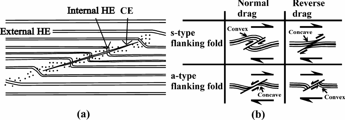
‘Flanking structures’ are ‘deflection of planar or linear fabric elements in a rock alongside a cross-cutting object’ (Passchier, Reference Passchier2001). The structural element which cuts across the earlier rock fabrics is called the ‘cross-cutting element’ (CE). The rock fabric that is cross-cut by the cross-cutting element is called the ‘host fabric element’ (HE). The part of the host fabric element that is curved near its contact to the cross-cutting element is called the ‘internal host fabric element’. The undeflected part of the host fabric element that is away from the cross-cutting element is called the ‘external host fabric element’ (Passchier, Reference Passchier2001). The domain within which the internal host fabric element is confined around the cross-cutting element is called the ‘internal host fabric element zone’ in this work (Fig. 1a). The internal host fabric element showing reverse faulting, normal faulting, or no fault movement across the cross-cutting element defines the ‘s-’, ‘a-’, or ‘n-type’ flanking structures, respectively (Grasemann, Stüwe & Vannay, Reference Grasemann, Stüwe and Vannay2003). If the host fabric element is convex (or concave) towards the direction of slip along the cross-cutting element, the drag of the host fabric element is called `normal’ (or ‘reverse’) (de Margerie & Heim, Reference De Margerie and Heim1888) (Fig. 1b). Any combination of drag and slip is possible in flanking structures (Passchier & Trouw, Reference Passchier and Trouw2005). However, a-type flanking structures with reverse drag are most common (Gomez Rivas et al. Reference Gomez-Rivas, Bons, Griera, Carreras, Druguet and Evans2007). A detailed review of the morphologies and classifications of flanking structures has been presented by Mulchrone (Reference Mulchrone2007).

Figure 1. Terminologies of flanking structure used in this work. (a) Diagrammatic representation of flanking structure. The dragged part of the host fabric element (HE) near the cross-cutting element (CE) is called the ‘internal HE’. Away from the internal host fabric element is the straight and undisturbed ‘external HE’. Reproduced from figure 1 of Passchier (Reference Passchier2001). The region within which the internal HE is confined, the dotted region in the diagram, is defined as the ‘internal HE zone’. (b) Different senses of slip and drag of the host fabric element for flanking structures. For this purpose, identification of a marker host fabric element, shown by the thick black line, would be a prerequisite. See text for definitions. Any combinations of senses of slip and drag are possible in flanking structures. Reproduced from figure 1 of Grasemann, Stüwe & Vannay (Reference Grasemann, Stüwe and Vannay2003).
Flanking structures have been reported at field scale in different geological contexts and rock types, but more commonly from mylonites (Passchier & Trouw, Reference Passchier and Trouw2005). While the cross-cutting element can be dyke, fracture, joint, fault, secondary shear plane/zone, vein, melt such as leucosome, burrow, inclusion, mineral or boudin, the host fabric element can be bedding plane, foliation, or lineation (as given in Passchier, Reference Passchier2001; Grasemann, Stüwe & Vannay, Reference Grasemann, Stüwe and Vannay2003 and references therein; Coelho, Passchier & Grasemann, Reference Coelho, Passchier and Grasemann2005; U. Exner, unpub. Ph.D. thesis, ETH Zürich, 2005; Mulchrone, Reference Mulchrone2007). Documentation of flanking structures at microscale has so far been scanty (photo 31 of Gansser, Reference Gansser1983; fig. 3 of Augustithis, Reference Augustithis1990; Shelley, Reference Shelley1994; fig. 6d of Grasemann & Stüwe, Reference Grasemann and Stüwe2001; fig. 12b of Mulchrone, Reference Mulchrone2007). No restriction of rigidity and thickness in defining the cross-cutting element was imposed in Passchier's (Reference Passchier2001) original definition of ‘flanking structures’, and this was followed by all subsequent workers, most notably by Coelho, Passchier & Grasemann (Reference Coelho, Passchier and Grasemann2005) who included rigid minerals cutting across foliations as flanking structures. Curvature of markers around mineral grains of different rigidities within ductile matrices and subjected to different shear regimes has been simulated in analog models (Ildefonse, Sokoutis & Mancktelow, Reference Ildefonse, Sokoutis and Mancktelow1992, for rigid grains; Odonne, Reference Odonne1994, for non-rigid grains) and numerical models (Ghosh & Sengupta, Reference Ghosh and Sengupta1973; Mulchrone, Reference Mulchrone2007) but as by-products of other kinematic studies. Whereas flanking structures with dominantly opposite senses of drag of the internal host fabric elements across the cross-cutting elements (figs 8I–V of Passchier, Reference Passchier2001) have received much interest (Grasemann & Stüwe, Reference Grasemann and Stüwe2001; Grasemann, Stüwe & Vannay, Reference Grasemann, Stüwe and Vannay2003; Exner, Mancktelow & Grasemann, Reference Exner, Mancktelow and Grasemann2004; Kocher & Mancktelow, Reference Kocher and Mancktelow2005; Wiesmayr & Grasemann, Reference Wiesmayr and Grasemann2005; Kocher & Mancktelow, Reference Kocher and Mancktelow2006), those with same senses of drag, though idealized (fig. 8V/ of Passchier, Reference Passchier2001), have received no further attention.
This paper aims at (i) morphological description, classification and restricted use of flanking structures as ductile shear-sense indicators at microscale; (ii) their morphological variation; and (iii) discussion of their observed rheological varieties. Additionally, flanking structures in microscale have been compared with those at field scale.
2. Flanking Microstructures
2.a. Sample location and definition
The studied thin-sections are prepared from the sheared rocks of the Higher Himalayan Crystalline unit (HHC) from the Zanskar and Alaknanda valleys in the NW Indian Himalaya. The Higher Himalayan Crystalline unit is the central core of the Himalaya, an intra-continental ductile shear zone, and is delimited by the Main Central Thrust (MCT) at the base and the South Tibetan Detachment System (STDS) at the top. The Higher Himalayan Crystalline unit is characterized by: (i) medium- to high-grade metamorphosed greenschist- to amphibolite-facies sequence of pelitic and psamitic rocks of Precambrian age; (ii) inverted metamorphism; (iii) main foliation (the primary shear C-plane) and the stretching lineation dipping NE; and a top-to-SW sense of contractional ductile shearing deciphered mainly from the S–C fabric and mineral fish (Jain, Singh & Manickavasagam, Reference Jain, Singh and Manickavasagam2002; Yin, Reference Yin2006 and references therein), and also from flanking structures at field scales (Grasemann, Fritz & Vannay, Reference Grasemann, Fritz and Vannay1999); and (iv) a heterogeneous shear regime with pure-shear-dominated flow in the centre and simple-shear-dominated flow at the boundaries (U. Exner, unpub. Ph.D. thesis, ETH Zürich, 2005 and references therein). The top-to-SW sense of ductile shearing is most pervasive in the Higher Himalayan Crystalline unit and is identified as the D2 phase of regional deformation possibly of the ~ 25 Ma early Neo Himalayan period. The Higher Himalayan Crystalline unit also underwent two phases of deformation before and after this shearing event as the pre-Himalayan D1 and post-shearing D3 folding events in local scales, respectively (Jain, Singh & Manickavasagam, Reference Jain, Singh and Manickavasagam2002 and references therein).
The studied thin-sections are XZ oriented, i.e. perpendicular to the main foliation and parallel to the stretching lineation. Under microscope usually at high magnification, these thin-sections reveal that some of the nucleated mineral grains cut and characteristically deflect cleavages (if any) and/or grain boundaries of the host grains. Here ‘nucleated minerals’ stands for minerals that grow over a pre-existing fabric or other minerals. Such nucleated minerals are designated as the cross-cutting element, the deflected cleavages and grain boundaries as the host fabric element, and the CE–HE composite as the flanking microstructure (FM) (Figs 2a, b, 3a–d, 4a, b, d, 5). Keeping in mind the definition of flanking structure of Passchier (Reference Passchier2001), where the ‘deflection’ (or the ‘drag’ of Grasemann, Stüwe & Vannay, Reference Grasemann, Stüwe and Vannay2003) of the host fabric element has been considered essential, we state that nucleated minerals that have only cut (Fig. 2c), or have cut and faulted the cleavages/grain margins (Fig. 2d) without any drag, will not be considered as the flanking microstructures.

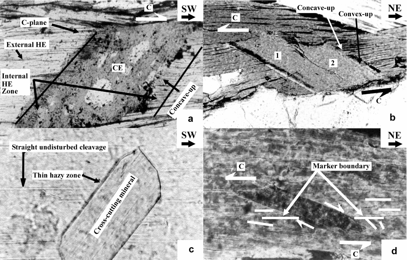
Figure 2. (a) Type 1 FM defined by nucleated biotite CE, and swerved cleavages of the host grain as the HE. The right and the left margins of the CE are characterized by HEs that are concave-up and convex-up, respectively. The parallelogram shape of the CE indicates a top-to-right (top-to-SW regional) shearing. This, and all the subsequent examples of Type 1 FM (Figs 2a, b, 3c, d, 4a, b, d), characteristically lack ‘marker HE’. In all these cases, the HEs, bounding the CE, act as the primary shear plane (the C-plane) along which ductile shear took place in the grain scale, and the cross-cutting element mineral underwent crystal-plastic deformation. Higher Himalayan Crystalline unit, Padam, Zanskar valley; plane-polarized light; photomicrograph length 2 mm. (b) Type 1 FM defined by two adjacent parallelogram-shaped biotite CEs (marked by 1 and 2), and dragged cleavage HEs of the host biotite. The CEs 1 and 2 indicate top-to-left (top-to-SW regional) shearing. The right margin of CE 2 displays both concave-up and convex-up senses of drag. The left margin of CE 1 displays a thin hazy zone and almost straight HE. Higher Himalayan Crystalline unit, Joshimath, Alaknanda valley; plane-polarized light; photomicrograph length 1 mm. (c) A muscovite grain has nucleated and cut across cleavages of the host muscovite grain. A thin but prominent hazy zone is present at the left margin of the cross–cutting muscovite. The right margin of this muscovite is sharp. The cross-cut cleavages at both the margins of the nucleated grain are straight. In this case, cleavages of the host grain and the nucleated grain together will not be designated as the FM. See text for discussion. Higher Himalayan Crystalline unit, Badrinath, Alaknanda valley; plane-polarized light; photomicrograph length 0.5 mm. (d) A nearly parallelogram-shaped muscovite grain, nucleated within an aggregate of muscovite host, shows top-to-left (top-to-SW regional) shearing. A grain boundary of the muscovite host is identified as ‘marker’ based on the observation that, with respect to the particular orientation of the cross-cutting grain, the cleavage planes above (and below) the ‘marker boundary’ are parallel (and make an angle) to it. Some of these cleavage planes, at the top (and bottom) of the ‘marker boundary’, are shown by horizontal (and inclined) short thin lines. The marker boundary is not dragged although it was normal faulted along the margins of the cross-cutting mineral. The cross-cutting mineral and the cleavages of the host grain, considered together, cannot be designated as the FM. See text for discussion. The grain margins of the cross-cutting mineral are very sharp and no hazy zones exist. Higher Himalayan Crystalline unit, Padam, Zanskar valley; cross-polarized light; photomicrograph length 1 mm.

Figure 3. (a) Type 2 FM defined by biotite CE (label 1), and dragged HE cleavages of a biotite host grain (label 2). The external HEs are subparallel to the main foliation (not within the photograph). With respect to the particular orientation of grain 1, as that in the photograph, the HEs are strongly concave-up at both the sides of the CE. The inferred preferred direction of growth of the biotite CE is almost perpendicular to the external HE cleavages, and also to the main foliation. The direction is shown by an outlined arrow inside the CE grain. The CE grain is markedly elongated along its inferred direction of growth. Thin hazy zones exist at the HE–CE contact. The HE tends to penetrate the CE within this hazy zone, and is noted particularly where a black arrow is pointed. Muscovite grains, labelled 3, 4 and 5, cut grain 1. Grain 5 is concave-up with the same intensity of curvature as that of the HE. We interpret that grain 5 was affected by the preferred direction of growth of the CE and indicate its nucleation either prior or simultaneous to the growth of the latter. Straight grain boundaries and cleavages of grains 3 and 4 indicate that these grains nucleated after grain 1 stopped growing. Higher Himalayan Crystalline unit, Joshimath, Alaknanda valley; cross-polarized light; photomicrograph length 0.5 mm. (b) Type 2 FM defined by a garnet grain as the CE, with gently dragged concave-up margins of the biotite host grains as the HE. The HEs are variably dragged at the CE margin, and are marked by arrows. Inferred preferred direction of growth of the CE is shown by outlined arrow, which is at high angle to the grain margin. The CE is slightly elongated along its preferred direction of growth. The HE–CE contact is sharp. Higher Himalayan Crystalline unit, Badrinath, Alaknanda valley; plane-polarized light; photomicrograph length 0.5 mm. (c) Type 1 FM defined by sheared, nearly sigmoid-shaped, alkali feldspar, at extinction position, as the CE and dragged cleavages of the muscovite host grains as the HE. In this case, the FM type is inferred not from the senses of drag of the HE, but from the shape of the CE. CE shape indicates top-to-left (top-to-SW regional) shearing. Straight and undisturbed HE cleavages, bounding the CE, act as the C-planes. The HEs are intensely dragged into both convex-up and concave-up senses at the same margin of the CE, and are shown by arrows p and q respectively. One of the margins of the feldspar grain is inclined to the C-plane in the direction of shear at x = 134°. One possible explanation for the two senses of drag at the same margin of the CE can be that the CE underwent simple shearing, initiating from x< 20° to the present angle. At one side of the CE, from arrow q towards arrow r, the convexities of the internal HEs are gradually reduced. At the other margin of the CE, the HEs are gently convex-up. Higher Himalayan Crystalline unit, Joshimath, Alaknanda valley; cross-polarized light; photomicrograph length 1 mm. (d) Type 1 FM defined by a parallelogram-shaped muscovite CE and gently swerved HE cleavages of a host grain of muscovite. The shape of the CE indicates a top-to-right (top-to-SW regional) shearing. The HEs are variably dragged into gently convex-up at the left side of the CE, shown by the arrow p; and are nearly straight and not dragged at the other margin, shown by the arrow q. Higher Himalayan Crystalline unit, Joshimath, Alaknanda valley; plane-polarized light; photomicrograph length 1 mm.

Figure 4. (a) Type 1 FM defined by a nucleated muscovite (mus) CE, and swerved HE cleavages of the biotite (bt) host grain at one side of the CE. Quartz (qz) is the other host mineral for the CE. The arrow points at prominent concave-up HEs defined by cleavages that are observed only at one side of the CE. The curved line drawn demarcates the contact between muscovite and quartz. Migration of quartz towards muscovite has partly eaten the latter. Had there been no migration, the muscovite would have been parallelogram-shaped. This is inferred from the non-orthogonal angular relation, shown by two short lines and angle x = 61° between the adjacent straight, therefore original, margins of the muscovite CE unaffected by grain boundary migration. Two long thin straight lines show the inferred grain boundaries of the CE. Reconstructed parallelogram shape of the CE indicates top-to-right (top-to-SW regional) shearing. Note that the C-planes are parallel to the HE. Higher Himalayan Crystalline unit, Padam, Zanskar valley; plane-polarized light; photomicrograph length 1 mm. (b) Type 1 FM defined by a nearly parallelogram-shaped muscovite CE and HEs of deflected cleavages, and grain boundaries of the host aggregate of biotite grains. CE shape indicates top-to-right (top-to-SW regional) shearing. Note that the C-planes are parallel to the HE. Thin hazy zones, labelled p and q, occur at the contacts between the HE and the CE. These diffuse zones cannot be resolved with the present magnification (photomicrograph length 2 mm). Interestingly, at ten times higher magnification, as in (c) (photo length 0.2 mm), the diffuse zone p, demarcated by two parallel lines, reveals the internal HE to be strongly convex-up. Better visibility at this very high magnification is achieved by focusing (yellow) light on the thin-section from an external source (in addition to what is available from the microscope), but at the cost of slightly changed observed colour of the minerals. (b, c) Higher Himalayan Crystalline unit, Badrinath, Alaknanda valley; plane-polarized light. (d) A Type 2 FM within a Type 1 FM. The Type 1 FM is defined by nearly parallelogram-shaped muscovite (mus) nucleated within an aggregate of biotite (bt). The CE shape indicates top-to-right (top-to-SW regional) shearing. Gently concave-up cleavages of the biotite host, shown by the arrow p, define the HE. The curved line drawn demarcates the contact between the muscovite and the quartz (qz) grains. Migration of quartz–muscovite boundary towards muscovite has partially destroyed the latter mineral. Had there been no such migration, the parallelogram shape it should have had is reconstructed by extrapolating adjacent sides of the muscovite by straight lines having an angle x = 45°. The pair of HEs bounding the CE defines the C-planes. Interestingly, the muscovite CE for the Type 1 FM has also acted as the host for an opaque mineral to nucleate. A Type 2 FM is defined by this opaque as the CE, and the leftward convex-up dragged cleavages at both sides (shown by arrows q and r) as the HE. The arrow within the rectangle shows the preferential direction of growth of the opaque. Higher Himalayan Crystalline unit, Padam, Zanskar valley; plane-polarized light; photomicrograph length 0.5 mm.

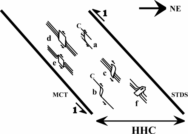
Figure 5. The observed FM and other important microstructures represented in the XZ section of the Higher Himalayan Crystalline unit (HHC), which is also the NE–SW geographic section. The HHC is bounded by the NE-dipping Main Central Thrust (MCT) to the south and the South Tibetan Detachment System (STDS) to the north. The half arrows labelled 1 at the boundaries of the HHC imply a top-to-SW contractional ductile shearing, revealed mainly from S–C fabric and mineral fish (examples a and b, respectively; from Jain, Singh & Manickavasagam, Reference Jain, Singh and Manickavasagam2002 and references therein). CEs of Type 1 FMs demonstrate a top-to-SW sense of shearing (examples c, d and e). These CEs are either sigmoid- (example c; natural example is Fig. 3c) or parallelogram-shaped (examples d and e; natural examples Figs 2a, b, 3d, 4a, b, d). A Type 2 FM showing preferential directional growth of its CE (example f; natural examples Figs 3a, b, 4d) is also shown. Note: the sketch is not to scale; the true relative location of examples a–f from within the HHC are not maintained; and not all morphological variations of the flanking microstructures are presented.
2.b. Description, classification and shear-sense indication
Amongst the observed varieties of flanking microstructure, micas most commonly define the cross-cutting element, and also the host mineral(s) over which the cross-cutting element nucleated (Figs. 2a, -b, 3a, -d). The host fabric elements are curved near their contacts to the cross-cutting element minerals, thereby defining the internal host fabric element. Compared to the flanking structures reported from field scale, the cross-cutting element of the observed flanking microstructure is usually thicker than the internal host fabric element zones.
Flanking structures at field scale are classified into ‘s-’, and ‘a-’ (or ‘n-’) type based on the sense of slip (or no slip) of the marker host fabric element across the cross-cutting element (Fig. 1b; Passchier, Reference Passchier2001; Grasemann, Stüwe & Vannay, Reference Grasemann, Stüwe and Vannay2003). From measurements of geometric parameters of drag folds associated with flanking structures, an estimation of vorticity is also possible (Gomez-Rivas et al. Reference Gomez-Rivas, Bons, Griera, Carreras, Druguet and Evans2007). However, these exercises are untenable for flanking microstructures since cleavages or grain boundaries defining the host fabric elements usually cannot be distinguished as markers. In turn, this hinders the categorization of the sense of drag of the internal host fabric element into the normal or the reverse type (see Grasemann & Stüwe, Reference Grasemann and Stüwe2001; U. Exner, unpub. Ph.D. thesis, ETH Zürich, 2005, for similar problems arising at field scale). Alternately, therefore, the sense of drag for the flanking microstructure can be described as ‘convex-up’ or ‘concave-up’, which is presumably dependent on the orientation of the thin-section on the stage of the microscope (Fig. 2a and its caption). Depending on whether the sense of drag of the internal host fabric element at the two margins of the cross-cutting element is different or the same, the flanking microstructure, and similarly the flanking structures at field scale, can be classified into Type 1, and Type 2 varieties, respectively. For a particular orientation of the thin-section on the microscope stage, if the internal host fabric element at one of the margins of the cross-cutting element mineral is ‘concave-up’, they are ‘convex-up’ at its other margin for Type 1 (Figs 2a, b, 3c, d, 4a, b; flanking microstructures c, d, e in Fig. 5; see also photo 31 of Gansser, Reference Gansser1983, and figs 8I–V of Passchier, Reference Passchier2001), and are ‘concave-up’ for Type 2 flanking microstructures (Figs 3a, b; flanking microstrucure f in Fig. 5; see also fig. 3 of Augustithis, Reference Augustithis1990, and fig. 8V/ of Passchier, Reference Passchier2001).
In his figure 8V/, Passchier (Reference Passchier2001) recognized intrusions and burrows as the cross-cutting elements and the adjacent bedding planes displaying the same senses of drag as the host fabric elements. Such flanking structures belong to Type 2. An intrusion, whether magma (fig. 3.22A of Montgomery, Reference Montgomery1987), diapiric salt (Chapman, Reference Chapman1973) or a burrow of trace fossil (fig. 2.1b of Bromley, Reference Bromley1990), makes the adjacent bedding/foliation planes concave-up towards its movement direction. Similarly, the unidirectional preferred growth of the cross-cutting element minerals of Type 2 flanking microstructure is deciphered to be from the convex towards the concave side of the internal host fabric elements. These cross-cutting elements can be defined either by a low-grade (Fig. 3a) or a high-grade mineral (Fig. 3b), which grow in a preferential direction, usually at a high angle (~ 70–85°), to the external host fabric element defined by the cleavages (Fig. 3a) or grain margins (Fig. 3b) of the host minerals. These cross-cutting elements are elongated to various degrees. The deformation that causes the internal host fabric elements to curve near the cross-cutting elements of Type 2 flanking microstructures is an exclusively microtectonic phenomenon of grain growth, and is unrelated to the regional deformation events of the Higher Himalayan Crystalline unit. Though not encountered in the present study, flanking microstructures defined by cross-cutting element minerals with two preferred growth directions 180° apart from each other do exist (fig. 3 of Augustithis, Reference Augustithis1990).
Most of the natural examples of flanking structures described from field scale (Grasemann, Fritz & Vannay, Reference Grasemann, Fritz and Vannay1999; Grasemann & Stüwe, Reference Grasemann and Stüwe2001; Passchier, Reference Passchier2001; Grasemann, Stüwe & Vannay, Reference Grasemann, Stüwe and Vannay2003; Coelho, Passchier & Grasemann, Reference Coelho, Passchier and Grasemann2005; U. Exner, unpub. Ph.D. thesis, ETH Zürich, 2005; Grasemann, Martel & Passchier, Reference Grasemann, Martel and Passchier2005; Kocher & Mancktelow, Reference Kocher and Mancktelow2005; Wiesmayr & Grasemann, Reference Wiesmayr and Grasemann2005; Exner, Grasemann & Mancktelow, Reference Exner, Grasemann, Mancktelow, Buiter and Schreurs2006; Færseth, Reference Færseth2006; Kocher & Mancktelow, Reference Kocher and Mancktelow2006; Patel & Kumar, Reference Patel and Kumar2006) and almost all the flanking microstructures encountered in the present study belong to the Type 1 variety. Since the opposite sense of drag across the cross-cutting element, as observed in Type 1 flanking microstructure, has been simulated in a number of analogue models (Exner, Mancktelow & Grasemann, Reference Exner, Mancktelow and Grasemann2004 and references therein; U. Exner, unpub. Ph.D. thesis, ETH Zürich, 2005; Exner, Grasemann & Mancktelow, Reference Exner, Grasemann, Mancktelow, Buiter and Schreurs2006) and numerical models (Grasemann & Stüwe, Reference Grasemann and Stüwe2001; Grasemann, Stüwe & Vannay, Reference Grasemann, Stüwe and Vannay2003; Kocher & Mancktelow, Reference Kocher and Mancktelow2005; Wiesmayr & Grasemann, Reference Wiesmayr and Grasemann2005) in various ductile shear regimes in relation to ‘flanking structures’, and also in the contexts of behaviour of clasts in various shearing regimes (Ghosh & Sengupta, Reference Ghosh and Sengupta1973) and their degree of bonding with the matrix (Ildefonse, Sokoutis & Mancktelow, Reference Ildefonse, Sokoutis and Mancktelow1992; Odonne, Reference Odonne1994), the Type 1 flanking microstructures are inferred to be the product of ductile shearing of the rock which contains them. Type 1 flanking microstructures are characterized by usually parallelogram-shaped (Figs 2a, b, Figs 3d, Figs 4a, b; Fig. 5 examples d and e) and less often sigmoid-shaped cross-cutting elements (Fig. 3c; Fig. 5 example c). In case of variable sense and degree of curvature of a few internal host fabric elements along the same and/or the different margins of the cross-cutting element, the shape constraint of the cross-cutting element can therefore be used as an alternative criterion to identify the Type 1 flanking microstructure.
A pair of parallel grain boundaries of the parallelogram-shaped cross-cutting elements of Type 1 flanking microstructures is bounded by a pair of external host fabric elements (Figs 2a, b, 3c, d, 4a, b, d). A pair of external host fabric elements also envelops the sigmoid-shaped cross-cutting elements of the Type 1 flanking microstructures (Fig. 3c). Under microscope, these external host fabric elements are found to be parallel to the NE-dipping C-planes. Thus, in addition to imposing possible mechanical anisotropy (Kocher & Mancktelow, Reference Kocher and Mancktelow2006) in the ductile shear regime, the grain boundaries and the brittle cleavage planes of the host mineral(s) efficiently acted as ductile primary shear planes of the D2 deformation phase so that cross-cutting elements of Type 1 flanking microstructures deformed crystal-plastically. The C-planes formed simultaneously to the ductile shearing (Lister & Snoke, Reference Lister and Snoke1984). Therefore, nucleation of the cross-cutting elements of Type 1 flanking microstructures is either pre- or syntectonic. On the other hand, as the cross-cutting element minerals of Type 2 flanking microstructures merely cut across the host fabric elements but are not ductilely sheared, their nucleation is presumably post-tectonic. Here ‘tectonic’ stands for the top-to-SW regional ductile shearing in the Higher Himalayan Crystalline unit.
Numerical modelling has shown that, depending on the initial angle between the host fabric element acting as the C-plane and the cross-cutting element, Type 1 flanking structures can form not only in a simple shear regime (Grasemann & Stüwe, Reference Grasemann and Stüwe2001), but also for different ratios of pure to simple shear within a thinning (Grasemann, Stüwe & Vannay, Reference Grasemann, Stüwe and Vannay2003) or a thickening general shear regime (Wiesmayr & Grasemann, Reference Wiesmayr and Grasemann2005), whereby the cross-cutting element may undergo rigid body rotation (figs 1, 2, 6 and 7 of Grasemann & Stüwe, Reference Grasemann and Stüwe2001; figs 3, 5 and 8 of Wiesmayr & Grasemann, Reference Wiesmayr and Grasemann2005; fig. 5.47 of Passchier & Trouw, Reference Passchier and Trouw2005), or ductile deformation (fig. 6b of modelled flanking structure of Passchier, Mancktelow & Grasemann, Reference Passchier, Mancktelow and Grasemann2005); all the Type1 flanking microstructures presented here). Deciphering the sense of non-coaxial shearing from the flanking structures at field scale is further complicated by the fact that reverse a-type flanking structures and reverse shear bands are geometric mirror images of each other (Grasemann, Stüwe & Vannay Reference Grasemann, Stüwe and Vannay2003), and contractional a-type and s-type flanking structures bear a morphological resemblance (Wiesmayr & Grasemann, Reference Wiesmayr and Grasemann2005), rendering limited the application of flanking structures at field scale in shear-sense determination (Passchier & Coelho, Reference Passchier and Coelho2006). However, these problems do not arise for Type 1 flanking structures in microscale, since their shear sense can be deduced based solely on the shape and the inclination of the cross-cutting elements with respect to the host fabric elements without considering the sense of drag of the internal host fabric elements (see examples d and e in Fig. 5). Within the spatially heterogeneous shear regime of the Higher Himalayan Crystalline unit (U. Exner, unpub. Ph.D. thesis, ETH Zürich, 2005 and references therein), the occurrence of parallelogram- and sigmoid-shaped cross-cutting element mineral grains (Figs 2a, b, 3c, d, 4a, b, d; examples c to e in Fig. 5) and their inclination synthetic to the top-to-SW primary shear direction indicate their non-coaxial shearing is the same as that of S–C fabrics and mineral fish as reported from the Higher Himalayan Crystalline unit by Jain, Singh & Manickavasagam (Reference Jain, Singh and Manickavasagam2002) and flanking structures at field scale by Grasemann, Fritz & Vannay (Reference Grasemann, Fritz and Vannay1999).
For some natural examples of flanking structures at field scale, the drag and the slip of the host fabric elements along the cross-cutting element margins are usually facilitated by the presence of a lubricating phase at the HE–CE contact: e.g. partial melt (Passchier, Reference Passchier2001), infiltrating fluids (Passchier & Trouw, Reference Passchier and Trouw2005) or incompetent rock such as shale (Færseth, Reference Færseth2006); and transparent silicon oil as performed in analog models (U. Exner, unpub. Ph.D. thesis, ETH Zürich, 2005, Exner, Grasemann & Mancktelow, Reference Exner, Grasemann, Mancktelow, Buiter and Schreurs2006). Contrary to this, the flanking microstructures encountered in this study (Figs 2a, b, 3a–d, 4a–d) reveal neither melt phase nor any recrystallization at the HE–CE contacts. This indicates that, for the flanking microstructures, (a) rheological weakening at these contacts is not an essential criterion for the host fabric elements to get dragged (and probably slipped) along the cross-cutting element margins; and (b), to account for the additional fact that the cross-cutting element minerals of Type 1 flanking microstructures reported here are crystal-plastically deformed or ‘non-rigid’ (Fig. 2a and its caption), a high degree of bonding between the nucleated cross-cutting element with the host mineral must exist (cf. Odonne, Reference Odonne1994). For some of the Type 2 flanking microstructures, significant dragging of the host fabric element cleavages/grain margins may be the result of such strong bonding between the cross-cutting element to the host grain and/or intense directional growth of the cross-cutting element (Fig. 3a).
2.c. Morphological variations
Important morphological variations of the flanking microstructures, observed mainly amongst the Type 1 variety, are as follows.
2.c.1. Variation 1
1A. At one particular margin of the cross-cutting element, the intensity and sense of drag of different internal host fabric elements can vary. This variation can be of two types: 1A1 – the internal host fabric elements may display visually decipherable progressively reducing curvature (Fig. 3c), similar to what has also been observed at field scale (Passchier & Trouw, Reference Passchier and Trouw2005); 1A2 – the drag of few of the host fabric elements may be opposite to the rest of them (Fig. 3c). Similar natural examples have been reported in the field in rare cases (Grasemann, Stüwe & Vannay,. Reference Grasemann, Stüwe and Vannay2003; Wiesmayr, Hinsch & Grasemann, Reference Wiesmayr, Hinsch and Grasemann2004; fig. 11a of Coelho, Passchier & Grasemann Reference Coelho, Passchier and Grasemann2005; Grasemann, Martel & Passchier, Reference Grasemann, Martel and Passchier2005 and references therein; Wiesmayr & Grasemann, Reference Wiesmayr and Grasemann2005). Analogue modelling (Exner, Mancktelow & Grasemann, Reference Exner, Mancktelow and Grasemann2004; U. Exner, unpub. Ph.D. thesis, ETH Zürich, 2005) showed that non-coaxial shearing of the cross-cutting element that initiates from a low angle to the shear zone boundary (< 20°) and reaches a higher angle (20–160°), or starts from a higher angle and ends at a still higher value (>160°), switches the sense of drag of the host fabric element from normal to reverse, or reverse to normal, respectively (also stated in Mulchrone, Reference Mulchrone2007). Similarly, in microscale, prolonged rotation of the cross-cutting element induced by ductile shearing might give rise to variable sense of drag of the host fabric element as a result of preservation of the previous sense of drag as relic fabric. Alternately, the same result could be reached due either to a (temporally?) heterogeneous displacement field along the cross-cutting element (Grasemann, Martel & Passchier, Reference Grasemann, Martel and Passchier2005), or mechanical anisotropy in the ductile shear regime (Kocher & Mancktelow, Reference Kocher and Mancktelow2006) imparted by cleavage planes along which brittle slip of minerals is favoured and by grain margins that act as the host fabric elements.
1B. The host fabric element may be dragged and curved only at one of the margins of the cross-cutting element mineral (Fig. 3d). This may indicate that in microscale the bond between the cross-cutting element and the host mineral varies at its different margins. At field scale, similar situations have been encountered: (i) a dyke as cross-cutting element and metasedimentary layers as host fabric elements (fig. 3B of Rice, Reference Rice1986); (ii) an elongated clast as cross-cutting element and foliations as host fabric elements (fig. 10c of Rajesh & Chetty, Reference Rajesh and Chetty2006).
2.c.2. Variation 2
When a cross-cutting element mineral nucleates over two minerals, with one of the host minerals lacking cleavages, the internal host fabric element may be defined, and hence also the flanking microstructure, by dragged cleavages at a single margin of the cross-cutting element (Fig. 4a). Thus, while at one of its boundaries the bond between the cross-cutting element and the host mineral is visually decipherable, that at the other boundary remains speculative.
2.c.3. Variation 3
In some cases, margins of the cross-cutting element minerals in contact with the internal host fabric elements are found to be thin zones of haziness, both in Type 1 (Figs 2b, 4b) and Type 2 flanking microstructures (Fig. 3a). Focusing the microscope lens at a particular margin of a cross-cutting element renders the opposite margin of the cross-cutting element defocused. Usually at higher magnification, these zones reveal strongly curved host fabric elements, which tend to penetrate the cross-cutting element (Figs 2b, 3a, 4b). However, it is important to note that the occurrence of hazy zones is not exclusive to the flanking microstructure. For example, it has also been noted around a mineral that has merely cut but not dragged the cleavages of the host mineral (Fig. 2c). At field scale, diffuse boundaries at the contact between the migmatite wall rock and the vein cross-cutting element (Passchier, Reference Passchier2001) are comparable with the hazy zones in the flanking microstructure.
2.c.4. Variation 4
Rare observations are:
4A. The host mineral, over which the flanking microstructure of one type has developed, can act as the cross-cutting element for a different type of flanking microstructure (Fig. 4d). In such cases the relative time relationship between the two different events (i.e. grain growth and ductile shearing) could not be established.
4B. The flanking microstructure can be disturbed by other grain-scale phenomena such as (4B1) migration of the boundary of an adjacent grain (Fig. 4a) or the host grain itself (Fig. 4d) leading to partial destruction of the cross-cutting element mineral; and (4B2) both the host fabric element and the cross-cutting element may be cut by a number of other mineral grains. If these other mineral grains are curved in sympathy with the growth of the cross-cutting element (grain 5 in Fig. 3a), the former grains might have grown prior or simultaneous to that of the cross-cutting element. Conversely, if those mineral grains are undeformed and unaffected by the growth of the cross-cutting element (grains 3 and 4 in Fig. 3a), the cross-cutting element might have nucleated and grown before those grains.
2.d. Rheological variations
Considering the HE–CE composite to be Newtonian viscous, the genesis of flanking structures (Type 1 in our scheme) has been established by Grasemann & Stüwe (Reference Grasemann and Stüwe2001) to be a function of the ratio of viscosity between the cross-cutting element and the host fabric element. For example, according to these workers, a rigid cross-cutting element within a weaker host mineral is expected to give rise to an a-type flanking structure. A microscale example of this could be a ductilely sheared feldspar grain that acts as the cross-cutting element and a muscovite grain as the host fabric element (Fig. 3c). However, whether the flanking microstructure is of a- or s-type cannot be checked due to the unavailability of the host fabric element as a marker. When both the host and the nucleating minerals are of the same species and presumably of the same viscosity, e.g. a biotite grain nucleated within a biotite host grain, the host fabric element and the cross-cutting element behave as a single object (Grasemann & Stüwe, Reference Grasemann and Stüwe2001), and drag and slip of the host fabric element are not expected. However, in the present study, drag of cleavages of the host grain has been noted under microscope even if the flanking microstructure is defined by the cross-cutting element and the host fabric element of the same mineral species (Figs 2a, b, 3d). This indicates that some variations in viscosity between the host fabric element and the cross-cutting element grains of the same mineral do exist. The third possibility, i.e. the flanking microstructure defined by a weak cross-cutting element and a more viscous host fabric element, which was numerically simulated for a simple-shear heterogeneous deformation regime with flow perturbation (Passchier, Mancktelow & Grasemann, Reference Passchier, Mancktelow and Grasemann2005), and for which n-type flanking structures are expected for a quite high viscosity contrast (Grasemann & Stüwe, Reference Grasemann and Stüwe2001), has not been encountered in the present study.
3. Conclusions
X–Z oriented thin-sections from the Higher Himalayan Crystalline unit, NW Indian Himalaya, reveal that nucleated minerals cut and drag cleavages and grain margins of the host mineral(s). The former minerals are designated as the cross-cutting elements (CE), cleavages and grain margins as the host fabric elements (HE) and the HE–CE composite as the flanking microstructure (FM). The cross-cutting elements of the studied flanking microstructures are usually micas and are thicker than the internal host fabric element zones. Unavailability of the host fabric element as a marker precludes deciphering the sense of slip. Therefore, instead of using standard terminologies to describe the curvature of the host fabric elements, the terms ‘convex up’ and ‘concave up’ are used. Depending on whether the senses of drag of the host fabric elements at the two sides of the cross-cutting element are different or the same, the flanking microstructures are grouped into Type 1 and Type 2 varieties, respectively. The latter type indicates preferential growth of the cross-cutting element from the convex towards the concave direction of the internal host fabric element and is a post-tectonic event exclusive to the microscale. The Type 1 flanking microstructures are products of ductile shearing. Their cross-cutting elements are parallelogram- or sigmoid-shaped, simple sheared with a top-to-SW sense that matches with other shear-sense indicators. The other criterion to identify the Type 1 flanking microstructure is from the shapes of their cross-cutting elements. Bounded by host fabric elements that also act as ductile primary shear C-planes, nucleation of these cross-cutting elements are either pre- or syntectonc. The cross-cutting elements of Type 1 flanking microstructures are reliable ductile shear-sense indicators in microscale irrespective of the specific shear regime. Lack of rheological weakening at the HE–CE contacts for the studied flanking microstructures indicates that it is not an essential criterion for the drag (and slip) of host fabric elements in microscale. This, along with the fact that the reported cross-cutting elements are non-rigid, indicates that the cross-cutting elements are strongly coupled with the host minerals. Variation in the intensity and senses of drag of internal host fabric elements of the Type 1 flanking microstructure has been noted along the same and different margins of the cross-cutting elements. This may be due to (a) considerable rotation of the cross-cutting element in simple shearing; (b) heterogeneous displacement field around the cross-cutting element; or (c) mechanical anisotropy imposed by the host fabric elements. The internal host fabric element may be defined only at a single side of the cross-cutting element when one of the host minerals lacks cleavages. A thin hazy zone may mark the HE–CE contact for the flanking microstructure of both types. The internal host fabric elements are strongly swerved and penetrate the cross-cutting element within this zone. The Type 1 flanking microstructure with (i) rigid cross-cutting element and a weaker host mineral, and (ii) cross-cutting element and the host grain of the same minerals, have been observed. The second observation indicates that a small variation in viscosity between the cross-cutting element and the host mineral must exist even when they belong to the same species.
Acknowledgements
SM acknowledges the Swedish Institute's ‘Guest Scholarship’ during 2005–2006. HAK was supported by the Swedish Research Council. Thanks to J. Carreras and an anonymous reviewer for their in-depth constructive criticism. J. Carreras suggested the more appropriate term ‘flanking microstructure’ in place of our ‘microflanking structure’.