1. INTRODUCTION
In inertial confinement fusion (ICF), a driver efficiency and its repetitive operation with several Hz ~ 15 Hz or so are essentially important to constitute an ICF reactor system. Heavy-ion beam (HIB) driver accelerators have a high driver energy efficiency of 30–40% from the electricity to the HIB energy. In addition, high-energy accelerators have been operated repetitively daily. The high driver efficiency relaxes the requirement for the fuel target gain. In heavy-ion inertial fusion (HIF) the target gain of ~50 would be needed to construct HIF fusion reactor systems.
In ICF target implosion, the requirement for the implosion uniformity is very stringent, and the implosion non-uniformity must be less than a few % (Emery et al., Reference Emery, Orens, gardner and Boris1982; Kawata & Niu, Reference Kawata and Niu1984). Therefore, it is essentially important to improve the fuel target implosion uniformity. In general, the target implosion non-uniformity is introduced by a driver beams’ illumination non-uniformity, an imperfect target sphericity, a non-uniform target density, a target alignment error in a fusion reactor, etc. The target implosion should be robust against the implosion non-uniformities for the stable reactor operation.
The HIB must be transported in a fusion reactor, which would be filled by a debris gas plasma. The reactor radius would be 3–5 m or so. From the beam exit of the accelerator the HIB should be transported stably. The HIB ion is rather heavy. For example, Pb+ ion beams could be a promising candidate for the HIF driver beam. Fortunately the heavy ions are transported almost ballistically with straight trajectories in a long distance. Between the HIB ions and the background electrons, the two-stream and filamentation instabilities may appear, and simple analyses confirm that the HIBs are almost safe from the instabilities’ influences. However, the HIB's self-charge may contribute to a slight radial expansion of the HIBs especially near the fuel target area due to the neutralized electrons’ heating by the HIB radial compression during the HIB's propagation in a reactor (Kawata et al., Reference Kawata, Sonobe, Someya and Kikuchi2005). So the HIB charge neutralization is also discussed in this paper. In this paper, a ceramics annular tube is discussed to supply a plasma surrounding each HIB at the HIB accelerator final section. The annular ceramics guide provides electrons to neutralize the HIB space charge.
A preliminary HIB reactor component is also presented. The target implosion uniformity requirement requests the minimum HIB number: details HIBs energy deposition on a direct-drive deuterium and tritium (DT) fuel target shows that the minimum HIBs number would be the 32 beams (Miyazawa et al., Reference Miyazawa, Ogoyski, Kawata, Someya and Kikuchi2005; Ogoyski et al, Reference Ogoyski, Someya and Kawata2004a , Reference Ogoyski, Someya and Kawata b , Reference Ogoyski, Kawata and Popova2010). Therefore, a reactor chamber should have at least 32 HIB ports at the reactor wall. When a ceramics annular guide is installed at the accelerator final section, each HIB charge neutralization ceramics tube supplies electrons to neutralize each HIB's charge. At the same time the inner surface of the ceramics tube may also absorb the reactor backflow gas to protect the accelerator device. In addition, multiple mechanical shutters would be installed at each HIB port at the reactor wall to stop the blast waves and the chamber gas backflow, so that the accelerator final elements would be protected from the reactor gas contaminant. The essential fusion reactor components are discussed in this paper.
2. KEY POINTS IN HIF ABOUT TARGET AND BEAM PLUSE
In this section, key points in HIF are summarized. The fuel target design should be conducted further toward a robust fuel implosion, ignition, and burning. The HIF target design is quite different from the laser fusion target due to the relatively long range (the order of about several hundred μm ~ 1 mm) of the HIB energy deposition (Kawata & Niu, Reference Kawata and Niu1984; Kawata et al., Reference Kawata, Karino and Ogoyski2016). In laser ICF, the ablator thickness may be about ~200 µm or so (Park et al., Reference Park, Hurricane, Callahan, Casey, Dewald, Dittrich, Doppner, Hinkel, Berzak Hopkins, Le Pape, Ma, Patel, Remington, Robey and Salmonson2014) and the ablator would consist of light materials. In HIF, the energy deposition layer would be heavy materials to stop the HIB ions.
An example direct-drive fuel target is presented in Figure 1. The target should be compressed to about 1000 of the solid density to reduce the driver energy and to enhance the fusion reactions (Atzeni & Meyer-Ter-Vehn, Reference Atzeni and Meyer-Ter-Vehn2009). The target should be robust against the small non-uniformities caused by the driver beams’ illumination non-uniformity, a fuel target alignment error in a fusion reactor, the target fabrication defect, etc. The ICF reactor operation frequency would be 10–15 Hz or so. So the stable target performance should be realized. The HIB stopping range is rather long, and the HIB beam energy is deposited mainly at the end area of the beam ion stopping range due to the Bragg peak effect, which is originated from the nature of the Coulomb collision. The interaction of the HIB ions could be utilized to enhance the HIB preferable characteristics. The HIB ion interaction is relatively simple, and is almost the classical Coulomb collision, except the plasma range-shortening effect (Ichimaru, Reference Ichimaru2004).
Fig. 1. An example fuel target structure in HIF.
However, the HIBs illumination scheme should be studied intensively to realize a uniform energy deposition in an HIF target. The ICF target implosion uniformity must be less than a few % (Emery et al., Reference Emery, Orens, gardner and Boris1982; Kawata & Niu, Reference Kawata and Niu1984). The uniformity requirement must be fulfilled to release the fusion energy. The multiple HIBs should illuminate the HIF target with a highly uniform scheme during the imploding DT shell acceleration phase.
In addition, the HIB pulse shape should be also designed to obtain a high implosion efficiency η. An example Pb+ HIBs pulse shape is presented in Figure 2. The pulse shape consists of a low-intensity foot pulse, a ramping part to the peak intensity and the high-intensity main pulse (Park et al., Reference Park, Hurricane, Callahan, Casey, Dewald, Dittrich, Doppner, Hinkel, Berzak Hopkins, Le Pape, Ma, Patel, Remington, Robey and Salmonson2014; Kawata et al., Reference Kawata, Karino and Ogoyski2016). The foot pulse generates a weak shock wave in the target material and the DT fuel, and the first shock wave kicks the low-temperature DT liquid fuel inward. When no foot pulse is used, the main pulse with the high intensity generates a strong first shock wave inside of the DT fuel and increases the DT adiabat. The DT fuel preheat would be induced. The foot pulse length and the ramping time are designed to reduce the entropy increase in the DT fuel layer. The first weak shock wave is not caught by the second and third stronger shocks inside of the DT fuel layer. At the inner edge of the DT fuel layer the strong shocks should be overlapped, so that the efficient fuel acceleration and compression are accomplished during the implosion. The detail pulse shape should be designed for each target design.
Fig. 2. An input heavy ion beam pulse. The HIB pulse consists of the low power part (foot pulse) and the high power one (main pulse).
The reactor design is also another key point in ICF (Emery et al., Reference Emery, Orens, gardner and Boris1982; Kawata & Niu, Reference Kawata and Niu1984; Kawata et al., Reference Kawata, Sonobe, Someya and Kikuchi2005). The first wall could be a wet wall with a molten salt or so or a dry wall. The reactor design must accommodate a large number of HIBs beam port, for example, 32 beam ports. At the first wall and the outer reactor vessel the beam port holes should have mechanical shutters or so to prevent the fusion debris exhaust gas toward the accelerator upstream. In addition, the target debris remains inside of the first wall or mixes with the liquid molten salt, which may be circulated. The target debris treatment should be also studied as a part of the reactor design.
The HIB accelerators have the high controllability and flexibility for the particle energy, the beam pulse shape, the pulse length, the ion species, the beam current, the beam radius, the beam focusing, and the beam axis motion. However, the high-current operation may need additional studies for the fusion reactor design. The a few ~10 kA HIB may induce an additional HIB divergence, a beam loss and an electron cloud generation in the accelerator. The high-current and high-charge HIB generation and transport should be studied carefully to avoid the uncertainty in the HIB accelerator (Bangerter et al., Reference Bangerter, Faltens and Seidl2013).
3. TARGET GAIN REQUIREMENT FOR HIF REACTOR SYSTEM
A target energy gain required for an energy production is evaluated by a reactor energy balance in ICF shown in Figure 3. The driver pulses deliver an energy E d to a target, which releases fusion energy E fusion. The energy gain is G = E fusion/E d. The fusion energy is first converted to electricity by a standard thermal cycle with an efficiency of ηth. A fraction f of the electric power is circulated to the reactor system operation and the driver system, which converts it to the HIB energy with an efficiency of ηd. The energy balance for this cycle is written by fηthηd G > 1. Taking ηth = 40% and requiring that the circulated-energy fraction f of electrical energy should be <1/4, we find the condition Gηd > 10. For a driver efficiency in the range of ηd = 30–40%, the condition G ≳ 30 is required for power production. Therefore, the preferable fusion target gain would be G ~ 50–70 in HIF. When the HIF reactor system operation is about 10–15 Hz, a 1 GW HIF power plant can be designed.

Fig. 3. Energy balance in ICF reactors.
4. HIB STABLE TRANSPORT IN A FUSION REACTOR
The HIB should be focused and transported in a fusion reactor against the beam space charge onto a fuel pellet at the reactor center. The target radius is the order of mm. One of the promising transport schemes is the neutralized ballistic transport, in which preformed-plasma electrons or wall-emitted electrons neutralize the HIB space charge. On the other hand, the HIB ion number density increases from n b0 ~ 1011–1012 cm−3 at a HIB port entrance to 100–200 × n b0 at the fuel pellet position. As a practical HIB neutralization method in an HIF reactor, an insulator annular tube guide was proposed at the final transport part, through which a HIB is transported (see Fig. 4) (Kawata et al., Reference Kawata, Someya, Nakamura, Miyazaki, Shimizu and Ogoyski2003). A local electric field created by the intense HIB induces local discharges, and a plasma is produced at the annular insulator inner surface. The electrons are extracted from the plasma by the HIB net charge. The electrons neutralize the HIB charge, and move together with the HIB in the reactor chamber (see Figs 5–8).

Fig. 4. A conceptual diagram of an HIF reactor. First, beam is transported through the ceramics Insulator guide. Second, beam transport through the reactor gas. Third, after the fusion reactions, the reactor gas expands in a reactor. Finally, the generated gas will enter the beam port.

Fig. 5. Electron extraction mechanism to compensate the HIB space charge. An intense HIB creates a strong electric field at the insulator ceramics annular guide inner surface, and induces the electric discharges, which produces a plasma at the annular insulator surface. From the created plasma the HIB extract electrons to neutralize the HIB net charge in the regulated way.
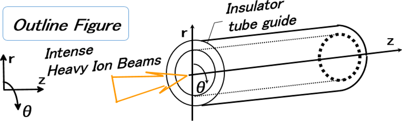
Fig. 6. Concept of an annular insulator guide for HIB charge.

Fig. 7. Input Pb+ ion beam waveform. The Pb+ ion-beam parameter values are as follows: the maximum current is 5 kA, the particle energy is 8 GeV, the pulse width is 10 ns, and the rise and fall times are 2.0 ns.

Fig. 8. Pb+ ion particle map and electron map in the case without the annular insulator guide and with the annular insulator guide. The focal radius is 2.4 mm at Z = 2.1 m with the guide, and 6.0 mm at Z = 2.1 m without the guide.
In addition, the chamber background electron density should be always larger than or equal to the HIB number density: n ce > Z b n b. Here, n ce is background electrons density, Z b is degree of ionization and n b is the HIB density. In our design, the fusion reactor is filled with helium gas, and its density is ~1016–1017 liter/cm3. In this case, the HIB space charge is always neutralized in the reactor well. The instability analyses were also performed including the two-stream instability and the filamentation instability. The maximum growth rate of the two-stream instability between the HIB ions and the background electrons is given by Eq. (1) (Okada & Niu, Reference Okada and Niu1981).
 $${\rm \gamma} _{{\rm max}} = - {\rm \nu} + \sqrt {\displaystyle{{\rm \pi} \over 2}} \displaystyle{{{\rm \omega}_{\rm b}^2} \over {{\rm \omega} _{\rm p}}}\displaystyle{{{(V_{\rm b} - u_{\rm b}/\sqrt 2 )}^2} \over {u_{\rm b}^2}} {\rm exp}\left( { - \displaystyle{1 \over 2}} \right).$$
Here the collision frequency is evaluated by the Coulomb interaction between the background electron and the HIB ions, whose speed is V b and thermal speed is u b. The HIB ion plasma frequency is denoted by ωb, and ωe is the background electron plasma frequency. The maximum growth rate of the filamentation instability is given by Eq. (2) (Okada & Niu, Reference Okada and Niu1981).
 $${\rm \gamma} _{{\rm max}} = 2\displaystyle{{{\rm \omega} _{\rm b}^2} \over {{\rm \omega} _{\rm p}^2}} \displaystyle{{V_{\rm b}^2} \over {u_{\rm b}^2}} {\rm \nu}.$$
The two-stream and filamentation instability analyses are summarized in Figure 9. It was found the two-stream instability is stabilized, and the filamentation instability could be unstable. However, the product of the growth rate and the HIB transport time is small, that is, γτ ≤ 5 or so.

Fig. 9. Panel (a) shows the growth rate of the two-stream instability and panel (b) shows the growth rate of the filamentation instability. The two-stream instability is always stable in the reactor. However, the product of the growth rate and the HIB transport time is small, that is, γτ ≤ 5 or so.
5. REACTOR CAVITY GAS
In this section, a reactor chamber gas dynamics is studied by using a simple analysis (Bondorf et al., Reference Bondorf, Garpman and Zimanyi1978; Zel'dovich & Raizer, Reference Zel'dovich and Raizer2002). A simple spherically symmetric fireball in a fusion reactor is estimated by the equation of continuity, the equation of motion and the equation of state for the adiabatic expansion:
 $$\displaystyle{{\partial {\rm \rho}} \over {\partial t}} + \left( {\displaystyle{1 \over {r^2}}} \right) \,\cdot\, \displaystyle{{\partial (r^2{\rm \rho} u)} \over {\partial r}} = 0,$$
 $$\displaystyle{{\partial u} \over {\partial t}} + u\displaystyle{{\partial u} \over {\partial r}} = - \displaystyle{1 \over {\rm \rho}}\, \cdot\, \displaystyle{{\partial p} \over {\partial r}},$$
 $$\displaystyle{\,p \over {{\rm \rho} ^{\rm r}}} = {\rm constant}{\rm.}$$
One of the solutions is the ZBG (Zimanyi, Bondorf and Garpman) solution (Bondorf et al., Reference Bondorf, Garpman and Zimanyi1978):
 $$R^2\left( t \right) = R_0^2 + \left\langle {u_{\rm t}} \right\rangle ^2\left( {t - t_0} \right)^2,$$
 $${\rm \rho} \left( {t,r} \right) = {\rm \rho} _0\left( {\displaystyle{{R_0^3} \over {R^3}}} \right)\cdot\left( {1 - \displaystyle{{r^2} \over {R^2}}} \right)^{\rm \alpha},$$
 $$T\left( {t,r} \right) = T_0\, \cdot\, \left( {\displaystyle{{R_0^2} \over {R^2}}} \right) \cdot \left( {1 - \displaystyle{{r^2} \over {R^2}}} \right),$$
 $${\rm \alpha} = \displaystyle{{m{\left\langle {u_{\rm t}} \right\rangle} ^2} \over {2T_0}} - 1.$$
Here R 0, ρ0, and T 0 are the initial values for the radius of the fireball, its density and its temperature, respectively. R(t), ρ(t, r), and T(t, r) are the time-dependent functions of the fireball outer radius, the density profile, and the temperature distribution. In addition, m is the particle mass of the fireball, and 〈u t〉 is the initial thermal speed of the expansion. Figure 10 shows the spatial profiles of T(t, r), and Figure 11 shows ρ(t, r) at each time. In Figures 10 and 11, R 0 = 5.0 × 10⁻³ m, ρ0 = 806 kg/m3, and T 0 = 5.31 × 10⁴ eV. In this work, α = −0.5 is employed, and we obtain a simple adiabatic expansion of the blast wave gas. In one shot of the DT fuel target implosion, ignition and burning, the initial temperature would be ~10 keV or so. In this case, the sound speed of C s ~ 〈u t〉 ~ 6 × 107 cm/s or so. Therefore, the blast wave traveling time τ in a fusion reactor chamber may be ~500 cm/6 × 107 cm/s ~ 8 µs. The target-debris chamber gas density would be of the order of 1 ~ a few torr or so, which corresponds to the gas number density of 2 × 10¹³ liter/cm3, after the blast wave reaches the chamber wall. Without the chamber gas supply, the expansion of the chamber gas after the target burning may make the target-debris gas dilute. During each shot, the chamber gas may be actively supplied to keep the high-density chamber gas in the chamber. When the reactor system operated with a 10–15 Hz, the blast wave propagation is too fast to give a significant interaction between the blast waves. The blast wave expands vary fast in ~8 µs, and the time interval for two DT fuel target implosions is about 1/15–1/10 s. In our reactor design, the helium gas is filled in the reactor chamber. By the fireball expansion, the reactor gas density becomes lower, due to the interaction of the fireball with the background helium gas. The time interval of 1/15–1/10 s between the two target shots is sufficiently long to refill the fresh helium gas in the reactor chamber (Oka et al., Reference Oka, Maratame, Miya, Kondo, Nakazawa, Tagawa, Iwata, Tanaka, Shimotono, Akiyama, Kobayashi, Hishikura, Furuta and Ogata1982).

Fig. 10. Temperature spatial profiles of T(t, r) for the fireball at R(t = 4 µs) = 2.5 m, R(t = 6 µs) = 3.75 m and R(t = 8 µs) = 5.0 m.

Fig. 11. Density spatial profiles of ρ(t, r) for the fireball at R(t = 4 µs) = 2.5, R(t = 6 µs) = 3.75 and R(t = 8 µs) = 5.0 m.
On the other hand, a part of the exhaust gas, the target debris and the reactor gas may come up to the accelerator final elements as a back flow. The vacuum of the accelerator part should be kept to the low pressure to avoid the HIB ions scattering and the halo formation.
6. PROTECTION OF HIF ACCELERATOR FROM BACKFLOW REACTOR GAS
In the HIF reactor system, we may have the ceramics HIB transport annular guide (see Figs 5–8), whose inner surface would absorb the upcoming exhaust chamber gas to the accelerator final section. The ceramics material surface has many small holes, which absorb the debris gas and vapor (Kato et al., Reference Kato, Naito, Nawashiro, Kawakita, Hakoda and Kawata1995; Nishiyama et al., Reference Nishiyama, Kawata, Naito, Kato and Hakoda1995; Hanamori et al., Reference Ichimaru1998; Kawata et al., Reference Kawata, Someya, Nakamura, Miyazaki, Shimizu and Ogoyski2003). If the beam ports at the chamber wall have no mechanical shutters to stop the blast waves and the chamber gas flow, the accelerator final elements may meet the contamination. Hence, at the final part of each accelerator near the chamber wall, each accelerator final part may several mechanical shutters, and two pairs of the mechanical shutters would confine the exhaust gas and absorb it at the ceramics guide inner surface. The absorbed gas is reused to produce a plasma at the ceramics annular guide inner surface to supply the electrons to neutralize the next HIB space charge (see Fig. 5) (Kato et al., Reference Kato, Naito, Nawashiro, Kawakita, Hakoda and Kawata1995; Nishiyama et al., Reference Nishiyama, Kawata, Naito, Kato and Hakoda1995; Hanamori et al., Reference Hanamori, Kawata, Kato, kikuchi, Fujita, Chiba and Hikita1998; Kawata et al., Reference Kawata, Someya, Nakamura, Miyazaki, Shimizu and Ogoyski2003). This is a realistic solution to keep the accelerator final section clean from the chamber gas and debris. Figure 12 shows an example concept for the accelerator protection system.

Fig. 12. A concept of an HIF fusion reactor, which has a molten-salt liquid first wall. The helium chamber gas is also injected to keep the HIB charge neutrality. In this design, 32 HIBs are employed, and the HIB ports are also displayed in the figure. At each port the mechanical shutter pairs are installed to protect the accelerator final section from the reactor exhaust gas backflow.
In this example, in Figure 12, the front shutter rotates with the speed of 100 rotations/s. The first shutter stops the most part of the reactor gas backflow to the accelerator final part. The second shutter rotates with ten rotations per second. The reactor gas speed is about C s ~ 6.0 × 105 cm/s at the reactor wall, where the beam ports are located. Some part of the reactor exhaust gas is confined at the beam port section isolated by the two shutters. When the annular ceramics insulator guides are installed at the final beam port section, the reactor exhaust gas would be absorbed perfectly and the accelerator vacuum is kept well. In order to absorb the reactor backflow gas at the accelerator final part, several pairs of the mechanical shutters shown in Figure 12 would be required to keep the accelerator vacuum.
Figure 13 shows our present HIF reactor design, which has a molten-salt liquid first wall. The helium chamber gas is also injected to keep the HIB charge neutrality. In this design 32 HIBs are employed, and the HIB ports are also displayed in Figure 13. At each port the mechanical shutter pairs are installed to protect the accelerator final section from the reactor exhaust gas back flow. At the inner surface of the reactor first wall a thin LiPb layer forms a first-wall protection layer, and the LiPb fills the space between the first and the second walls. The operation frequency would be 12 Hz and the fusion thermal energy output is 3 GW to produce 1 GW electricity. Our further reactor conceptual studies in HIF will be performed in the near future to confirm the HIF reactor system feasibility.

Fig. 13. Mechanical shutters to protect the accelerator vacuum from the reactor exhaust gas backflow.
7. CONCLUSIONS
In this paper, we presented our recent research results relating to the HIF reactor core, including the fuel target implosion uniformity requirement, the target gain requirement, the HIB space charge neutralization method, the HIB focusing feature, the HIB instability study in a fusion reactor chamber, and the preliminary HIB reactor design. So far our studies have presented that the HIF reactor concept has no critical defect in order to construct a stable and reliable fusion power reactor system. We found also that the HIB reactor system is relatively simple in all aspects required in the HIF system. This finding would be preferable for our future HIF reactors.
ACKNOWLEDGMENTS
The work was partly supported by JSPS, MEXT, CORE (Center for Optical Research and Education, Utsunomiya University), ILE/Osaka University, and CDI (Creative Department for Innovation, Utsunomiya University). The authors also would like to extend their acknowledgements to friends in HIF research group in Japan, in Tokyo Institution of Technology, Nagaoka University of Technology, KEK and also in HIF-VNL, USA.