


1. Introduction
Advances in recent times in engineering and science disciplines have allowed researchers in the field of robotics to come up with biologically inspired soft-bodied robots capable of imitating the style of movement of their equivalent natural bodies. In the last decade, the locomotion mechanics of such biological lives as caterpillars [Reference Lin, Leisk and Trimmer1], snakes [Reference Onal and Rus2], octopus tentacles [Reference Laschi, Mazzolai, Mattoli, Cianchetti and Dario3], fish [Reference Marchese, Onal and Rus4], elephant trunk [Reference Salomon and Wolf5, Reference Bao, Chen, Zhang, Cai, Xu, Yang and Zhang6], and worms [Reference Tang, Lu, Wang, Ma, Chen and Feng7, Reference Seok, Onal, Cho, Wood, Rus and Kim8] have been imitated fancifully. Soft robotics is basically a cross-disciplinary research field that seeks to develop soft-bodied robots (made of highly compliant, large repetitive deformation sustaining materials) which can interact safely with humans and at large, with their proximate environment in a more flexible way than their rigid-bodied traditional counterparts [Reference Whitesides9]. Generally, the performance of these soft robotic systems is significantly dependent on their actuation means. The common ones include chemical [Reference Palleau, Morales, Dickey and Velev10, Reference Shepherd, Stokes, Freake, Barber, Snyder, Mazzeo, Cademartiri, Morin and Whitesides11], electrical [Reference Carpi, Bauer and De Rossi12, Reference Keplinger, Kaltenbrunner, Arnold and Bauer13], and pneumatic [Reference Chou and Hannaford14, Reference Amend, Cheng, Fakhouri and Culley15], hydraulic [Reference Ikuta, Ichikawa and Suzuki16, Reference Katzschmann, Marchese and Rus17], smart composite materials [Reference Laschi, Mazzolai, Mattoli, Cianchetti and Dario3, Reference Huu Nguyen, Alici and Mutlu18, Reference McGovern, Alici, Truong and Spinks19], each one having certain advantages and disadvantages that define its application. Pneumatic actuators have found extensive use in robotic/automated applications, including bio-inspired robotic products, grippers, rehabilitations devices, flow systems, as well as in miniaturized devices. They are lightweight, cost-effective, offer safe collaboration with their environment, and deliver with great mechanical advantage [Reference Ilievski, Mazzeo, Shepherd, Chen and Whitesides20, Reference Mosadegh, Polygerinos, Keplinger, Wennstedt, Shepherd, Gupta, Shim, Bertoldi, Walsh and Whitesides,”21]. Soft pneumatic actuators (SPAs) present better actuation features of their rigid counterparts due to simplicity and pliability. With the recent advancements in the development of soft materials, soft actuation methods that utilize pneumatic networks in deformable slender bodies have been presented [Reference Onal and Rus2, Reference Hwang, Paydar and Candler22, Reference Polygerinos, Lyne, Wang, Nicolini, Mosadegh, Whitesides and Walsh23]. Such SPAs are capable of generating a linear bending (one-directional) motion from a single pressure source. They have been used extensively in driving soft grippers [Reference Deimel and Brock24–Reference Yap, Ng and Yeow26].
Grasping objects using the conventional robotic grippers require complex control methods to ensure the application of a sufficient non-destructive grip force. Soft grippers in contrast, make an easy alternative. They can handle and interact with diverse kinds of objects without any sensor or complex control methods in place. For stable and secure gripping, a sufficient contact area is required between a gripper and the target object. The multi-finger gripper design inspired by the human hand has been regarded as an ideal model for gripper designs, both rigid and soft robotic systems [Reference Bicchi27]. An obvious reason is because, the regular pneu-net actuator which is their major driver produces bending curvature only in the longitudinal direction – as mentioned earlier. Consequently, a sufficient contact area for stable and secure grip cannot be obtained unless three, four (or more) of the actuators are combined [Reference Hu and Alici28–Reference Rothemund, Ainla, Belding, Preston, Kurihara, Suo and Whitesides30]. To achieve a high conformal gripping with reduced bulkiness, an enhanced structural design which can seamlessly assume a configuration that allows sufficient soft contact with target surfaces is required. Although some alternate designs of the pneu-net which exhibit more dexterous gripping capabilities have been reported [Reference Hu and Alici28, Reference Wang, Ge and Gu31], the combination of three or more pieces of these actuators is still required to realize practical grasping functions; hence, increase in material costs and structural complexities of soft grippers.
Here, we propose a new design of the pneu-net which can bend simultaneously about the transverse and longitudinal axes, thereby producing a concave configuration akin to the one the human palm. The structure is typified by two mirrored angle pneumatic chambers (in likeness of a herringbone gear teeth) whose thrusts (from the right and left) counteract each other to produce the coupled multi-directional bending deformation. We first study the bending behaviors of the actuator numerically and experimentally to obtain optimum design parameters for prospective applications. Then, we design a series of experiments to investigate the functional behaviors of the actuator/gripper prototypes. For proof of concept, we subject the gripper to a series of grasping tests using objects of different shapes, sizes, and weight. Finally, we employ the actuators as fingers in a hand rehabilitation device, capable of replicating the flexing motions of the human fingers for different desired gripping purposes.
2. Materials and Methods
2.1 Actuator design
Typical actuators based on pneu-nets are composed of two fundamental parts: an active top (characterized by a series of elastomeric chambers lined up in a row and linked up by a network of air channels) and a passive bottom (a strain-limiting layer which serves to curtail the extension of the active part) [Reference Mosadegh, Polygerinos, Keplinger, Wennstedt, Shepherd, Gupta, Shim, Bertoldi, Walsh and Whitesides,”21, Reference Guo, Li, Cheng, Zhang, Xu and Ding32, Reference Wakimoto, Suzumori and Ogura33]. On the supply of pressure to the actuator, the chambers expand (significantly across the length) and cause the whole structure to bend in the longitudinal direction only. In our study however, with basis on the mechanism of deformation of the aforementioned regular one, we present a new structure which is capable of combined bending in both longitudinal and transverse directions. The actuator, called ‘herringbone pneu-net actuator’, like the regular actuator structure, comprises an active top and a bottom layer; but here, the active layer’s configuration follows that of a herringbone gear, with two sets of mirrored angle chambers on the same layer. Each of the two chamber sides has an underlying equidistant/centralized air channel interconnecting chambers the longitudinally, referred to as, the ‘longitudinal channel’, and another set for the cross-connection of the chambers, referred to as the ‘cross channels’ (as depicted in Fig. 1). Another noteworthy feature of the design is the approach employed for constraining the deformation of the structure – in the sense of the characteristic function of the ‘strain-limiting’ layer of the regular design. In the traditional structure, high-stiffness materials (such with young’s modulus values higher than that of the base elastomer the actuator body is made of) such as paper, polyester fabric, and metal fiber are embedded for the strain control; in other words, different mechanical properties (of different materials) were combined to ‘program’ the direction of actuation of the structures. In our structure, however, there is homogeneity of material, as well as a leverage of wall thickness variation for the strain control, which presents an alternative approach to the use of heterogeneous materials for the strain control, as apparently the layer with the highest thickness (in this case the bottom layer) poses the largest resistance to stretching, defining the function of a strain-limiting layer thereby. So basically, expansion takes in all the parts of the structure, with the bottom layer ‘stretching’ simultaneously over both the longitudinal and transverse axes in response to the expansion of the inclined chamber volumes upon pressurization.
The structural parameters of the pneu-net actuator (as in Fig. 1), particularly the wall thickness, the chamber height, and the overall length of the structure (or number of pneu-nets) – are significant to its performance. Diverse responses can be obtained from actuator by altering or combining these parameters in different forms [Reference Hu and Alici28, Reference Wang, Ge and Gu31, Reference Sun, Zhang, Chen and Chen34]. In this work, we adopt an unprecedented parameter, the chamber inclination angle (CIA),
 $\theta $
, for the study of the functional behavior of the structure. The functional characteristics are investigated by varying the CIA parameter while others (i.e., length, width, height, etc.), as in Table I, are kept constant.
$\theta $
, for the study of the functional behavior of the structure. The functional characteristics are investigated by varying the CIA parameter while others (i.e., length, width, height, etc.), as in Table I, are kept constant.
Table I. Geometric parameters of the reference herringbone actuator.
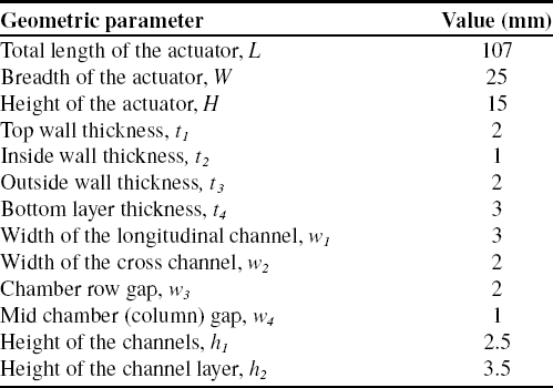
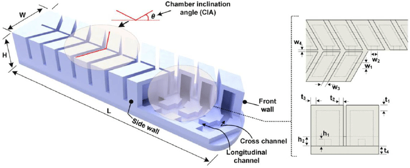
Figure 1. Basic structure of the pneu-net actuator with a herringbone chamber pattern.
2.2 Actuator fabrication
A conventional mold casting method was adopted for the prototype fabrication [Reference Adam Bilodeau, White and Kramer35, 36]. A tripartite mold was designed in SolidWorks2018 (Dassault Systèmes) and produced by 3-D printing technology (Material: Resin 8200). Two of the three parts are coupled together to make the top (active) layer, while the other works for the bottom (passive) layer. For the casting, the material components: Dragon Skin 30 parts A and B (Smooth-On Incorporation, Pennsylvania, USA) are first stirred separately – each for about 2 mins before being mixed together and stirred again for about 4 mins. Afterward, the mixture – still in the mixing bowl – is placed in a vacuum chamber for the removal of any entrapped air, before pouring it into the molds. The degassing process could take about 10 mins; it is important to get it quickly done, as the material’s pot life is just around 45 mins. Right after filling the molds to appropriate levels, they are placed in the vacuum pump for a second degassing phase to remove any air trapped-in in the course of the filling. By this time, the viscosity of the mixture must have increased considerably, a sign of the pot life drawing to a close. After that, the material is left to cure at room temperature for about 15 h. After the curing process is complete, the castings (i.e., the silicone top and bottom layers) are carefully removed from the molds and bonded together with the same Dragon Skin 30 (fresh mixture). Finally, though not compulsory, the assembled structure is heated in the oven at 80 °C for 2 h; this will aid quick attainment of optimal performance properties.
3. Results and Discussion
3.1 Inflation characterization
Computer modeling by finite element method (FEM) is quite a popular approach for studying deformation behaviors of structures in various areas, including soft robotics [Reference Hao, Wang, Ren, Gong, Wang, Yang, Guan and Wen37–Reference Antonelli, Beomonte Zobel, Durante and Raparelli39]. Going by the method, the distinctive deformation of the actuator structure was studied with respect to our reference parameter – the CIA,
 $\theta $
–toward an optimum design. Models of the actuator with varied CIA (
$\theta $
–toward an optimum design. Models of the actuator with varied CIA (
 $\theta $
= 0°, 10°, 20°, 30°) were first designed in SolidWorks, and then imported to the standard/implicit environment of the CAE package – Abaqus 6.14 (Dassault SystÈmes). The models were meshed with solid quadratic tetrahedron elements (element type C3D10H in Abaqus), with a global mesh seed (element size) of 1 mm. Surface interactions (between the chambers walls), as well as the influence of gravity were also considered in the setup. For an optimal capture of the mechanical behavior of the elastomer the actuator was fabricated from (Dragon Skin 30), an incompressible hyperelastic model was adopted. We used the first-order Ogden hyperplastic model, whose strain energy function is described by,
$\theta $
= 0°, 10°, 20°, 30°) were first designed in SolidWorks, and then imported to the standard/implicit environment of the CAE package – Abaqus 6.14 (Dassault SystÈmes). The models were meshed with solid quadratic tetrahedron elements (element type C3D10H in Abaqus), with a global mesh seed (element size) of 1 mm. Surface interactions (between the chambers walls), as well as the influence of gravity were also considered in the setup. For an optimal capture of the mechanical behavior of the elastomer the actuator was fabricated from (Dragon Skin 30), an incompressible hyperelastic model was adopted. We used the first-order Ogden hyperplastic model, whose strain energy function is described by,
 \begin{align} U = \sum\nolimits_{i = 1}^N {2\mu /\alpha _i^2{{(\lambda _1^{\alpha i} + \lambda _2^{\alpha i} + \lambda _3^{\alpha i} - 3)}^i} + \sum\nolimits_{i = 1}^N {1/{D_i}{{(J - 1)}^{2i}}} } \end{align}
where
 ${\rm{\lambda }}{{\rm{\;}}_i}$
is the constant for deviatoric principal stretch, D is the compressibility factor, J is the elastic volume ratio, and N is the number of terms [Reference Ogden40].
${\rm{\lambda }}{{\rm{\;}}_i}$
is the constant for deviatoric principal stretch, D is the compressibility factor, J is the elastic volume ratio, and N is the number of terms [Reference Ogden40].
The parameters used in the model were N = 1,
 ${\mu _1}$
=
${\mu _1}$
=
 $0.246 \pm 0.0078\;{\rm{MPa}}$
,
$0.246 \pm 0.0078\;{\rm{MPa}}$
,
 ${\alpha _1}$
=
${\alpha _1}$
=
 $3.0158 \pm 0.00453$
, and
$3.0158 \pm 0.00453$
, and
 ${D_i}$
= 0 (incompressibility) [Reference Wang, Or and Hirai41]. A material density of 1070 kg/m3 was set in accordance with the technical data sheet from the manufacturer (Smooth-on Incorporation) [42]. The simulated deformation results of the actuator are shown in Fig. 2. As anticipated, the regular actuator (i.e.,
${D_i}$
= 0 (incompressibility) [Reference Wang, Or and Hirai41]. A material density of 1070 kg/m3 was set in accordance with the technical data sheet from the manufacturer (Smooth-on Incorporation) [42]. The simulated deformation results of the actuator are shown in Fig. 2. As anticipated, the regular actuator (i.e.,
 $ = {0^\circ }$
, Fig. 2(a)) shows a pure longitudinal bending deformation (i.e., curvature only about the transverse axis), while its herringbone counterparts (Fig. 2(b)) show coupled bending curvature about the transverse and the longitudinal axes.
$ = {0^\circ }$
, Fig. 2(a)) shows a pure longitudinal bending deformation (i.e., curvature only about the transverse axis), while its herringbone counterparts (Fig. 2(b)) show coupled bending curvature about the transverse and the longitudinal axes.
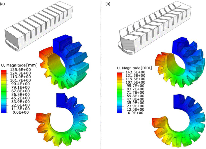
Figure 2. Simulated bending shape response of (a) the traditional pneu-net structure
 $(\theta = {0^{\circ}})$
at 55 kPa and (b) the proposed herringbone structure
$(\theta = {0^{\circ}})$
at 55 kPa and (b) the proposed herringbone structure
 $\theta = {30^{\circ}}$
at 60 kPa.
$\theta = {30^{\circ}}$
at 60 kPa.
The longitudinal bending of the structures was measured by angle
 $\alpha $
, from the Y–X displacement of the structure, as described in Fig. 3(a). With the increase of the input pressure from 10 to 60 kPa, a continuous increase in the deformation of the actuator and the bending angle was observed. The transverse axis was measured by angle
$\alpha $
, from the Y–X displacement of the structure, as described in Fig. 3(a). With the increase of the input pressure from 10 to 60 kPa, a continuous increase in the deformation of the actuator and the bending angle was observed. The transverse axis was measured by angle
 $\beta $
, as illustrated in Fig. 3(b) and (c). The estimation of
$\beta $
, as illustrated in Fig. 3(b) and (c). The estimation of
 $\beta $
follows the method described by Pruett et al. for estimating root canal curvature using two characteristic parameters: angle of curvature and radius of curvature [Reference Pruett, Clement and Carnes43]. According to the method, a straight line is drawn along the longitudinal axis of the left and the right halves of the curvature (Fig. 3(c)). There lies a point on each of these lines where the structure deviates to end or begin the curvature. The curved portion of the structure is characterized by a circle having tangents at these two points. Then, the angle of curvature is defined by the angle produced by perpendicular lines measured from the deviation points to intersect at the center of the circle. The length of the lines which is equivalent to the radius of curvature could therefore be used to explain how abrupt or lax the actuator’s transverse curvature is.
$\beta $
follows the method described by Pruett et al. for estimating root canal curvature using two characteristic parameters: angle of curvature and radius of curvature [Reference Pruett, Clement and Carnes43]. According to the method, a straight line is drawn along the longitudinal axis of the left and the right halves of the curvature (Fig. 3(c)). There lies a point on each of these lines where the structure deviates to end or begin the curvature. The curved portion of the structure is characterized by a circle having tangents at these two points. Then, the angle of curvature is defined by the angle produced by perpendicular lines measured from the deviation points to intersect at the center of the circle. The length of the lines which is equivalent to the radius of curvature could therefore be used to explain how abrupt or lax the actuator’s transverse curvature is.
Figure 3. Longitudinal and transverse bending angles of the actuator. (a) Sequential deformation images of 30° chamber angle variation of the actuator model, with an illustration of the corresponding bending angle, α measurement. (b) Front view of the actuator model (θ = 30°) at 40 kPa, illustrating the corresponding transverse curvature angle, β. (c) Measurement of the angle of transverse curvature.
Shown in Fig. 4 are simulation and experimental results illustrating the longitudinal and transverse bending angles of the herringbone structure as a function applied pressures over a range of
 $\theta $
values. As shown in Fig. 4(a), there is a steady increase in the longitudinal bending of both the regular (i.e.,
$\theta $
values. As shown in Fig. 4(a), there is a steady increase in the longitudinal bending of both the regular (i.e.,
 $\theta = 0$
) and the herringbone (i.e.,
$\theta = 0$
) and the herringbone (i.e.,
 $\theta = {10^\circ },\;{20^\circ },\;\;{\rm{and}}\;{30^\circ }$
) structures with pressure; the former, however, shows a quicker response than the latter – as there are more pneumatic networks in it than in the regular structure. As regard the herringbone category in particular, there appears to be no significant disparity between
$\theta = {10^\circ },\;{20^\circ },\;\;{\rm{and}}\;{30^\circ }$
) structures with pressure; the former, however, shows a quicker response than the latter – as there are more pneumatic networks in it than in the regular structure. As regard the herringbone category in particular, there appears to be no significant disparity between
 $\theta = {10^\circ }\;$
and
$\theta = {10^\circ }\;$
and
 $\theta = {20^\circ }$
over the pressure range (i.e., nearly same gradient); but
$\theta = {20^\circ }$
over the pressure range (i.e., nearly same gradient); but
 $\theta = {30^\circ }$
, in contrast, bends to roughly the same angle as its counterpart (
$\theta = {30^\circ }$
, in contrast, bends to roughly the same angle as its counterpart (
 $\theta = {10^\circ } \& \;{20^\circ }$
) up till 40 kPa pressure, from where there is a little surge in its gradient till the terminal 60 kPa. As for the transverse deformation (Fig. 4(b)),
$\theta = {10^\circ } \& \;{20^\circ }$
) up till 40 kPa pressure, from where there is a little surge in its gradient till the terminal 60 kPa. As for the transverse deformation (Fig. 4(b)),
 $\theta = {0^\circ }$
produces no curvature at all (i.e.,
$\theta = {0^\circ }$
produces no curvature at all (i.e.,
 $\beta $
= 0), while the herringbone structures produce increasing degrees of curvature as
$\beta $
= 0), while the herringbone structures produce increasing degrees of curvature as
 $\theta $
increases (with
$\theta $
increases (with
 $\theta = {10^\circ }$
,
$\theta = {10^\circ }$
,
 ${20^\circ }$
, and
${20^\circ }$
, and
 ${30^\circ }$
producing
${30^\circ }$
producing
 $\beta $
=
$\beta $
=
 $\sim {21^\circ }$
,
$\sim {21^\circ }$
,
 $\sim {32^\circ }$
and
$\sim {32^\circ }$
and
 $\sim {50^\circ }$
, respectively at 60 kPa).
$\sim {50^\circ }$
, respectively at 60 kPa).
To validate the simulation results, we conducted an experimental study on
 $\theta $
=
$\theta $
=
 ${10^{\circ}}$
,
${10^{\circ}}$
,
 ${20^{\circ}}$
, and
${20^{\circ}}$
, and
 $\;{30^{\circ}}$
prototypes of the actuator (movie s1). For the longitudinal bending angles, we oriented the actuators horizontally with their pressure supply ends secured in custom fixtures, and subjected them to same amount of pressure supply using a high precision pressure controller (ELVEFLOW OB1 Mk3 pressure control kit, France). We captured images of the actuators under same range of constant pressures with a high-definition camera positioned perpendicular to the respective planes of the transverse and longitudinal angles generated. By tracking the edges of structure as clearly highlighted in the high-definition images, we could extract the required points and lines for the estimation of the respective angles with the aid of the sketch picture tool in the SolidWorks part environment.
$\;{30^{\circ}}$
prototypes of the actuator (movie s1). For the longitudinal bending angles, we oriented the actuators horizontally with their pressure supply ends secured in custom fixtures, and subjected them to same amount of pressure supply using a high precision pressure controller (ELVEFLOW OB1 Mk3 pressure control kit, France). We captured images of the actuators under same range of constant pressures with a high-definition camera positioned perpendicular to the respective planes of the transverse and longitudinal angles generated. By tracking the edges of structure as clearly highlighted in the high-definition images, we could extract the required points and lines for the estimation of the respective angles with the aid of the sketch picture tool in the SolidWorks part environment.
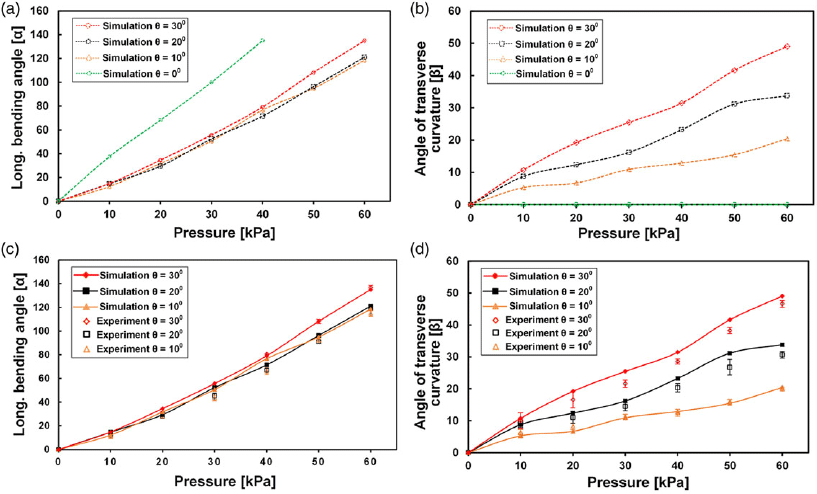
Figure 4. Relationship between input pressure and longitudinal and transverse angles of the actuator with varied CIA, θ. (a) and (b) show the simulation results, and (c–d) compare the simulation results with the experiment. The analyses and tests were conducted under the same range of input pressures (0–60 kPa; 5 kPa step). The error bars indicate the standard deviations of the experimental data.
Going by the aforementioned approach, we estimated
 $\alpha $
and
$\alpha $
and
 $\beta $
for each
$\beta $
for each
 $\theta $
variation, across the applied pressure steps. Fig. 4(c) and (d) comparatively illustrates the simulation and experimental results of all the prototypes. Both results can be seen showing good agreement (with the maximum variation of
$\theta $
variation, across the applied pressure steps. Fig. 4(c) and (d) comparatively illustrates the simulation and experimental results of all the prototypes. Both results can be seen showing good agreement (with the maximum variation of
 $\alpha $
less than 15%, 20%, and 9%, and that of
$\alpha $
less than 15%, 20%, and 9%, and that of
 $\beta $
, less than 19%, 16%, and 18% for
$\beta $
, less than 19%, 16%, and 18% for
 $\theta $
=
$\theta $
=
 ${10^{\circ}}$
,
${10^{\circ}}$
,
 ${20^{\circ}}$
, and
${20^{\circ}}$
, and
 $\;{30^{\circ}},$
respectively). Defects in fabrication procedure, undetected points of air leakage, image processing errors, limitations of the model used in describing the material’s hyperelastic behavior, and so on are common factors associable with these discrepancies. From the comparison of the obtained longitudinal (Fig. 4(c)) and the transverse (Fig. 4(d)) bending angles, it is evident that the effect of the CIA is much more significant on the transverse curvature than on the longitudinal.
$\;{30^{\circ}},$
respectively). Defects in fabrication procedure, undetected points of air leakage, image processing errors, limitations of the model used in describing the material’s hyperelastic behavior, and so on are common factors associable with these discrepancies. From the comparison of the obtained longitudinal (Fig. 4(c)) and the transverse (Fig. 4(d)) bending angles, it is evident that the effect of the CIA is much more significant on the transverse curvature than on the longitudinal.
It could be argued that adding an extra structure to the edges of the regular structure could be as good as the proposed structure in function (i.e., gripping with improved stability). While that is very reasonable, the point that our proposed structure – by the virtue of the characteristic CIA parameter which allows for variable transverse enclosure around target objects – may let us consider this an inclusion to the pool of options for potential applications.
3.2 Blocked force measurement
To estimate the force capacity of the herringbone actuator, a multi-axis force sensor (HZC-HI, ATI Automation, China; resolution:
 $ \pm $
0.1%, stability: 0.05%, sensing range: up to 100N) was utilized to measure the resultant force outputted by the actuator when pressurized. For the measurement, the actuator was mounted in form of a cantilever beam using a platform that allows the fixing of the rear end, and an unrestrained positioning of the front end on the sensor, as shown in Fig. 5(a).
$ \pm $
0.1%, stability: 0.05%, sensing range: up to 100N) was utilized to measure the resultant force outputted by the actuator when pressurized. For the measurement, the actuator was mounted in form of a cantilever beam using a platform that allows the fixing of the rear end, and an unrestrained positioning of the front end on the sensor, as shown in Fig. 5(a).

Figure 5. Blocked force test. (a) Experimental setup for the measurement of the actuators’ force capacity. (b) Force results from three prototypes (= 10°, 20°, and 30°).
CIA variations (i.e.,
 $\theta $
=
$\theta $
=
 ${0^{\circ}},$
 ${10^{\circ}}$
,
${10^{\circ}}$
,
 ${20^{\circ}}$
, and
${20^{\circ}}$
, and
 $\;{30^{\circ}}$
) were considered for the test, with the key aim of investigating the correlation between CIA and blocked force. The actuators were pressurized gradually in 5 kPa steps, while corresponding forces generated their tips were measured. The test was repeated three times at every pressure step for the sake of accuracy and repeatability. The results are summarized in Fig. 5(b). As can be seen in the figure, within the herringbone category, the measured output forces rise steadily with pressure in the three cases, with
$\;{30^{\circ}}$
) were considered for the test, with the key aim of investigating the correlation between CIA and blocked force. The actuators were pressurized gradually in 5 kPa steps, while corresponding forces generated their tips were measured. The test was repeated three times at every pressure step for the sake of accuracy and repeatability. The results are summarized in Fig. 5(b). As can be seen in the figure, within the herringbone category, the measured output forces rise steadily with pressure in the three cases, with
 $\theta $
=
$\theta $
=
 ${10^{\circ}},\;{20^{\circ}}$
, and
${10^{\circ}},\;{20^{\circ}}$
, and
 $\;{30^{\circ}}$
generating
$\;{30^{\circ}}$
generating
 $\sim\!0.89\;N$
,
$\sim\!0.89\;N$
,
 $\sim\!0.97\;N$
, and
$\sim\!0.97\;N$
, and
 $\sim\!1.25\;N$
, respectively, at 70 kPa (our terminus pressure). At relatively small input pressures, the longitudinal and transverse bending angles are small; hence, the weight of the actuator accounts for the substantial part of the measurement obtained; but as the supply pressure increases, the output force gradually takes over, increasing steadily with the input pressure. Thus, as can be seen in the figure, there is no appreciable gradient until around 25 kPa for
$\sim\!1.25\;N$
, respectively, at 70 kPa (our terminus pressure). At relatively small input pressures, the longitudinal and transverse bending angles are small; hence, the weight of the actuator accounts for the substantial part of the measurement obtained; but as the supply pressure increases, the output force gradually takes over, increasing steadily with the input pressure. Thus, as can be seen in the figure, there is no appreciable gradient until around 25 kPa for
 $\theta $
=
$\theta $
=
 ${10^{\circ}}$
, 15 kPa for
${10^{\circ}}$
, 15 kPa for
 $\theta $
=
$\theta $
=
 ${20^{\circ}}$
, and 5 kPa for
${20^{\circ}}$
, and 5 kPa for
 $\theta $
=
$\theta $
=
 ${30^{\circ}}$
. In the case of the traditional structure, the slope appears nearly the same as that of
${30^{\circ}}$
. In the case of the traditional structure, the slope appears nearly the same as that of
 $\theta $
=
$\theta $
=
 ${30^{\circ}}$
from 0 to 20 kPa, after which it takes a sharp increase, reaching up to 1.65 N at the terminus pressure. This is one advantage the structure has over herringbone design; being that all thrusts produced by the expansion of the zero-angled chamber are concentrated in the longitudinal direction only, unlike in the herringbone design where the forces are divided across both the length and the width of the structure to realize the cup-like bending curvature.
${30^{\circ}}$
from 0 to 20 kPa, after which it takes a sharp increase, reaching up to 1.65 N at the terminus pressure. This is one advantage the structure has over herringbone design; being that all thrusts produced by the expansion of the zero-angled chamber are concentrated in the longitudinal direction only, unlike in the herringbone design where the forces are divided across both the length and the width of the structure to realize the cup-like bending curvature.
3.3 Grip strength
Grip strength basically describes how firmly or securely a gripper can hold on to an object. In a technical sense, it is the magnitude of force a gripper is able to exert on or (spread around) a target object, by the virtue of which the firmness of the gripper on the object in the face of a dispossessive force is measured. For the study, we designed three 2-finger soft grippers (one with the conventional zero-angle chamber configuration, and the two others, the herringbone pattern (as in Fig. 6(a)), each made to grasp three test objects (viz, a tennis ball, a plastic container, and a carton box) under a set of actuation pressures, and then subjected to thrusts from the side of the unit (as shown in Fig. 6(b–d)i). We expected that the test would in a way show how the herringbone structure and its counterpart fare with three different geometric shapes – ball, cylinder (round face), and cuboid (flat face) – represented by the objects.

Figure 6. Grip strength measured in terms of resistance to side push forces. (a) The herringbone gripper model. (b–d)i The experimental setup for the grip force measurement and (b–d)ii comparison of the grip force of three gripper prototypes (θ = 0°, 10°, and 30°). Each test is repeated three times under the respective set of actuation pressures; the error bars indicate the standard deviation of the measurements.
As shown in Fig. 6(b–d)i, the pressurized gripper (
 $\theta $
=
$\theta $
=
 ${30^{\circ}}$
) with the test objects within its grip is laid on its side in to receive a downward push force. A 50 N capacity digital force gauge (HP-50, Yueqing Handpi Instruments, China; resolution: 0.01N, error:
${30^{\circ}}$
) with the test objects within its grip is laid on its side in to receive a downward push force. A 50 N capacity digital force gauge (HP-50, Yueqing Handpi Instruments, China; resolution: 0.01N, error:
 $ \pm $
0.5%) was employed for the measurement. The push force was applied at an approximate rate of 2 mm/s on the objects with the grippers’ actuation pressures for each object varied statically by 10 kPa (from 30 to 60 kPa for the ball, and 35–65 kPa for others to provide enough grip force). Figure 6(b–d)ii summarizes the measurement from the three prototype cases (i.e.,
$ \pm $
0.5%) was employed for the measurement. The push force was applied at an approximate rate of 2 mm/s on the objects with the grippers’ actuation pressures for each object varied statically by 10 kPa (from 30 to 60 kPa for the ball, and 35–65 kPa for others to provide enough grip force). Figure 6(b–d)ii summarizes the measurement from the three prototype cases (i.e.,
 $\;\theta $
=
$\;\theta $
=
 ${0^{\circ}}$
,
${0^{\circ}}$
,
 ${10^{\circ}}$
, and
${10^{\circ}}$
, and
 $\;{30^{\circ}}$
). Beginning with the ball, as can be seen from Fig. 6(b)ii, the regular structure (i.e.,
$\;{30^{\circ}}$
). Beginning with the ball, as can be seen from Fig. 6(b)ii, the regular structure (i.e.,
 $\theta $
=
$\theta $
=
 ${0^{\circ}}$
) succumbed to the smallest push force (3 N, 5 N, 6.5 N, and 9 N under 30 kPa, 40 kPa, 50 kPa, and 60 kPa applied pressures, respectively). The herringbone structures on the other hand, needed much higher push forces – nearly double and triple respectively of what was required with the traditional configuration (18.5N for
${0^{\circ}}$
) succumbed to the smallest push force (3 N, 5 N, 6.5 N, and 9 N under 30 kPa, 40 kPa, 50 kPa, and 60 kPa applied pressures, respectively). The herringbone structures on the other hand, needed much higher push forces – nearly double and triple respectively of what was required with the traditional configuration (18.5N for
 $\theta $
=
$\theta $
=
 ${10^{\circ}}$
and 27.5N for
${10^{\circ}}$
and 27.5N for
 $\theta $
=
$\theta $
=
 ${30^{\circ}}$
at 60 kPa). In the plastic container’s case (Fig. 6(c)ii) on the other hand, the regular structure relatively outperformed its herringbone counterparts (the former requiring about 3N, 6N, 7N, and 11N compared to the latter’s 2N, 3N, 4N, and 7N (for
${30^{\circ}}$
at 60 kPa). In the plastic container’s case (Fig. 6(c)ii) on the other hand, the regular structure relatively outperformed its herringbone counterparts (the former requiring about 3N, 6N, 7N, and 11N compared to the latter’s 2N, 3N, 4N, and 7N (for
 $\theta $
=
$\theta $
=
 ${10^{\circ}}$
), and 3N, 5N, 7N, and 9.5N (for
${10^{\circ}}$
), and 3N, 5N, 7N, and 9.5N (for
 $\theta $
=
$\theta $
=
 ${30^{\circ}}$
) at 35 – 65 kPa in 10 kPa steps, respectively). It was quite unsurprising, as the smooth round surface of the container allows sufficient contact area between it and the curling flat gripping surface of the gripper (regular); unlike with the curling cup-like deformation of the herringbones which would not fully lay on the surface of the container. Finally, with the carton box (Fig. 6(d)ii), the two structures were generally close in performance; the regular structure bettered the herringbone (
${30^{\circ}}$
) at 35 – 65 kPa in 10 kPa steps, respectively). It was quite unsurprising, as the smooth round surface of the container allows sufficient contact area between it and the curling flat gripping surface of the gripper (regular); unlike with the curling cup-like deformation of the herringbones which would not fully lay on the surface of the container. Finally, with the carton box (Fig. 6(d)ii), the two structures were generally close in performance; the regular structure bettered the herringbone (
 $\theta $
=
$\theta $
=
 ${10^{\circ}}$
) structure generally, but as the transverse curvature increased (
${10^{\circ}}$
) structure generally, but as the transverse curvature increased (
 $\theta $
=
$\theta $
=
 ${30^{\circ}}$
) the enclosure slightly proved a better constraint on the box.
${30^{\circ}}$
) the enclosure slightly proved a better constraint on the box.
3.4 Stability test: sustained grasping force
To find out more about the strengths and lapses of the herringbone structure relative to its counterpart, we designed a force-based test to investigate the stability of different shapes within the grasp of the gripper, going by the measurement of the most sustained applied force in course of lifting the object. For an all-round highlight of relative features of the two structures, we considered three kinds of objects based on shape, viz. round, flat, and irregular – represented by a mini cylindrical speaker, a digital display control, and an apple (details in Table 2). Each of the objects was mounted on base plate of the pull-push gauge and subjected to lift forces from both the regular and the herringbone (
 $\theta $
=
$\theta $
=
 ${30^{\circ}}$
) grippers (actuated under three different pressures: 35 kPa, 45 kPa, and 55 kPa). The arm of the gauge (to which the gripper was clamped) was displaced consistently at a constant speed of 2 mm/s to execute a simple pick-up motion. The grippers were not pressurized at the start of the displacements (so as to have them approach the objects with large openings) but rather close to the end (where appropriate enclosure on the objects could be achieved upon actuation), after which the arm would be set in reverse motion to lift the objects. The force monitor, meanwhile, was set to automatically capture the raw force data as the gripper interacted with the respective shapes. For quantitative comparison of the sustained lift forces, we extracted from each of the trials (three for each measurement) mode lift force (absolute nonzero value), and obtained their averages and standard deviations (for error estimations). Figure 7(a–c),i–ii shows the grasping/lifting positions of the regular and herringbone grippers, respectively, on each of the three target shapes, while Fig. 7(a–c),iii summarizes the sustained force measurements for the corresponding objects, over the three different actuation pressures.
${30^{\circ}}$
) grippers (actuated under three different pressures: 35 kPa, 45 kPa, and 55 kPa). The arm of the gauge (to which the gripper was clamped) was displaced consistently at a constant speed of 2 mm/s to execute a simple pick-up motion. The grippers were not pressurized at the start of the displacements (so as to have them approach the objects with large openings) but rather close to the end (where appropriate enclosure on the objects could be achieved upon actuation), after which the arm would be set in reverse motion to lift the objects. The force monitor, meanwhile, was set to automatically capture the raw force data as the gripper interacted with the respective shapes. For quantitative comparison of the sustained lift forces, we extracted from each of the trials (three for each measurement) mode lift force (absolute nonzero value), and obtained their averages and standard deviations (for error estimations). Figure 7(a–c),i–ii shows the grasping/lifting positions of the regular and herringbone grippers, respectively, on each of the three target shapes, while Fig. 7(a–c),iii summarizes the sustained force measurements for the corresponding objects, over the three different actuation pressures.
Table II. Target shapes employed in the sustained lift force test.

As can be seen from Fig. 7(a–c),iii which illustrate the stability of the two gripper configurations in terms of the most sustained lift force on the three different shapes considered, the herringbone gripper shows greater stability than its counterpart with the cylindrical surface, and even more with the irregular surface, but less with the flat surface – at low supply pressures. On the cylindrical shape, the herringbone gripper sustained lift forces 0.77N, 1.33N, and 1.93N (approx. total body weight of the object) compared to its counterpart’s 0.63N, 0.88N, and 1.13N under applied pressures 35 kPa, 45 kPa, and 55 kPa, respectively (Fig. 7(a),iii). Likewise, on the irregular shape, the results show greater stability with the herringbone than with the traditional – under the three applied pressures (Fig. 7(b),iii). Finally, on the rectangular part (Fig. 7(c),iii), the traditional gripper bettered the herringbone (especially at low pressures), sustaining values of about 2.96N, 2.96N, and 3.18N (equivalent to the weight of the object) compared to the 1.21N, 2.15N, and 3.04N of the herringbone gripper; the implication of which is that, more pressure is needed to hold on to flat faces with the cup-shaped deformation of the herringbone structure than with the one-directional bending of the regular structure (whose whole output force is concentrated across the length of the structure).
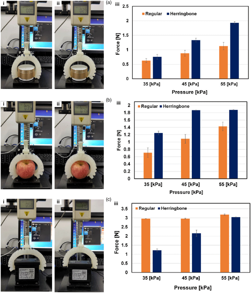
Figure 7. Sustained lift force test. Snapshots of the gripper ((i) regular (ii) herringbone) grasping/lifting positions, and (iii) comparison of the highest sustained lift force under three different supply pressures, on (a) a cylindrical shape, (b) an irregular shape, (c) a rectangular shape.
4. Application
4.1 Soft grasping
A couple of dexterous tests were conducted with the two-finger gripper –
 $\theta $
=
$\theta $
=
 ${30^{\circ}}$
to demonstrate the relatively high conformal gripping capability that comes with the herringbone chamber design. Figure 8 illustrates the experimental demonstration on kinds of objects, including a tea tin, an LED light bulb, wireless computer mouse, an aluminum cooling fin, a plastic cup, a glass beaker, a stopwatch, and a beverage can. As expected, the gripper generated coupled longitudinal and transverse bending curvatures from each wing actuator which combine to form a sort of half enclosure on the objects. The concave configuration of the structure could be adjusted by increasing or decreasing the applied pressure as according to the target object (in these examples, 35–65 kPa range was sufficient). The configuration allows the actuator to exert a stable grip by providing sufficient flexible contact with the surfaces of test objects (otherwise unobtainable from the one made of the regular pneu-net configuration). For objects with such irregular surfaces that would not allow sufficient surface contact with the gripping face, the gripper by its concave configuration still provides them sufficient security (with its curved end and side edges) such that would not fail even when shaken vigorously (movie s2).
${30^{\circ}}$
to demonstrate the relatively high conformal gripping capability that comes with the herringbone chamber design. Figure 8 illustrates the experimental demonstration on kinds of objects, including a tea tin, an LED light bulb, wireless computer mouse, an aluminum cooling fin, a plastic cup, a glass beaker, a stopwatch, and a beverage can. As expected, the gripper generated coupled longitudinal and transverse bending curvatures from each wing actuator which combine to form a sort of half enclosure on the objects. The concave configuration of the structure could be adjusted by increasing or decreasing the applied pressure as according to the target object (in these examples, 35–65 kPa range was sufficient). The configuration allows the actuator to exert a stable grip by providing sufficient flexible contact with the surfaces of test objects (otherwise unobtainable from the one made of the regular pneu-net configuration). For objects with such irregular surfaces that would not allow sufficient surface contact with the gripping face, the gripper by its concave configuration still provides them sufficient security (with its curved end and side edges) such that would not fail even when shaken vigorously (movie s2).

Figure 8. Grasping tests with gripper θ = 30°. The test objects are: (a) a tea tin, (b) a light bulb, (c) a stopwatch, (d) a beaker, (e) a plastic cup, (f) a beverage can, (g) a wireless computer mouse, (h) an aluminum cooling fin, and (i) a tennis ball. (a–i) illustrate a series of conformal grasp demonstrations of the two-finger herringbone gripper on different test objects.
4.2 Hand rehabilitation glove design and actuator incorporation
The application of the herringbone actuator is also extended to prosthetics in a hand rehabilitation glove capable of the flexing motions associated with the human fingers. Varying lengths (as in Table 3) of the herringbone finger matching those of a medium-sized human hand are incorporated into a neoprene glove to replicate required finger motions in a compliant, assistive, and safe manner, and at relatively low cost. The force capacities of the prototype fingers were obtained by the same approach illustrated in Fig. 5, where a multi-axis force/torque sensor was used to measure the magnitude of the resultant output force at the tip of the fingers.
Table III. Geometrical parameters and experimental force estimation of all fingers.


Figure 9. Prototype of the rehabilitation glove. (a–c) Top, bottom, and side views of the glove prototype in an open palm mode, showing the herringbone actuators with plastic braces at their individual ends, soft silicone tubes for air supply, elastic bands for the fingers, and a Velcro strap for the wrist/forearm. (d) The glove being used to grasp different objects.
The actuator was designed in the likeness of the human finger and fitted to the glove accordingly in an open palms configuration as shown in Fig. 9(a–c). The plastic braces at the supply ends of the actuators serve to enhance the fixture of the actuators there, while they also help to keep the air tubes properly aligned. The design (Fig. 9(a–c)) is such that facilitates effortless, comforting, and quick fitting to the hand. The glove is equipped with small elastic bands to help keep users' fingers in position, comfortably. These elastic bands combined with the Velcro fastenings allow a simple mounting and unmounting from the hand. The coupled transverse-longitudinal deformation capability of the structure allows a smooth spread of contact pressure over the back of each finger, thereby minimizing probable pains or discomfort from concentrated loading. To evaluate the performance of the glove with regard to its capability to provide an assistive function to the fingers in gripping, we subjected it to some autonomous grasping tests. The test objects are such which vary particularly in shape, weight, stiffness, and surface texture (a tennis ball, a plastic cup, a ceramic cup, and a plastic bag roll), as in Fig. 9(d). As supply pressure increases, the transverse and longitudinal bending curvatures of fingers, as well as the corresponding tip and side edge forces increase accordingly, boosting the overall gripping strength of the glove. An average supply pressure of 60 kPa was sufficient for conformal grasping of all the objects.
Overall, the distinctiveness of this herringbone structure has been shown through its ability to form a soft variable cup-like enclosure on its target objects – circumventing the need for extra finger(s) as with the use of the zero or other nonzero-angled chamber designs available in the literature [Reference Hu and Alici28–Reference Rothemund, Ainla, Belding, Preston, Kurihara, Suo and Whitesides30]. We found that most of these grippers also require relatively high actuation pressure. For instance, in Hu and Alici’s work (apparently the most related to ours in the literature) [Reference Hu and Alici28], there were four fingers (fully angled chambers as well as half-zero-angled-half-non-angled chambers) in their gripper unit – used on a variety of objects including a tennis ball, a mouse, a plastic container, as in our work; however, requiring a higher actuation pressure –160 kPa compared to ours – 35 to 65 kPa. Another example is Rothemund et al.’s earlier mentioned five-finger gripper, being of the same material as ours, still required a 69 kPa actuation pressure to pick up a tennis ball in the study [Reference Rothemund, Ainla, Belding, Preston, Kurihara, Suo and Whitesides30]. Wang et al.’s oblique actuator, used as single finger gripper, also required up to 90 kPa pressure to wrap around its tests objects [Reference Wang, Ge and Gu31]. Our gripper, like none in the literature, guarantees high conformal with the least number of fingers. Nevertheless, as already shown earlier, with flat-surfaced objects – where the transverse curvature of the gripping surface would literarily translate to reduced contact between it and the plane surface, the regular pneu-net structure would outperform the herringbone, thanks to its higher end tip force – actuation pressure ratio.
5. Conclusions
This study presents a new SPA with herringbone chamber design, capable of combined longitudinal and transverse bending deformations that allow for improved conformality in soft gripping. By FEM simulation and experiment, we studied the deformation behavior of the actuator in terms of the angles generated respectively about the transverse and longitudinal axes, using the characteristic CIA as control parameter. From the results, the transverse bending curvature increased significantly with increase in the CIA. Furthermore, to quantify the performance of the herringbone design relative to the traditional, we experimentally investigated the tip force, and grip strength, of the corresponding actuators/grippers, as well as the stability of three basic body shapes (round, rectangular, and irregular) within their grasps. From the results, the herringbone structure, though deficient in tip force compared to its traditional counterpart, showed greater grasp strength on the corresponding test object, as well as greater firmness on the body shapes. Finally, on the application front, the stable and secure gripping capability of the herringbone structure was demonstrated in a series to gripping tests, on objects of different shapes, weights, and textures. Furthermore, the actuator structure was optimized and implemented in a rehabilitation glove design to produce bending motions akin to flexing motions of the human fingers, to support grasping with bending load spread across both the length and the width of the fingers. Overall, we have shown how the combined transverse and longitudinal bending deformations of the proposed herringbone actuator offer high conformality in soft gripping compared with the traditional structure, bringing some advantages such as cost saving (from the material requirement of two fingers instead of three or more) and compactness of structure (from the number of fingers that have to be put together to effectively lift objects of different kinds). We believe this research could extend the boundaries of soft robotic capabilities and versatility, especially in the area of material handling.
Acknowledgements
This work was supported by the National Natural Science Foundation of China (No. 51905150), the Natural Science Foundation of Jiangsu Province (No. BK20190167), the Fundamental Research Funds for the Central Universities (No. B200202230), and China Postdoctoral Science Foundation (No. 2020T130097, 2019M651643).
Conflict of Interest
The authors declare they have no competing financial interests.
Supplementary Material
To view supplementary material for this article, please visit https://doi.org/10.1017/S0263574721001144


