I. INTRODUCTION
The design of horn antennas as a feed for reflector antennas is a challenging task particularly so for spaceborne antennas. The generic requirement or important considerations for space-worthy feed horn for a reflector antenna are (i) radiation pattern to exhibit a rotationally symmetric beam with appropriate beamwidth, (ii) a high degree of polarization-purity, (iii) the feed should be compact to minimize the volumetric requirements and feed blockage due to the ray bundle reflected from the reflector, (iv) simplification in the mechanical design and ease in manufacturing (v) light-weight, and (vi) the horn should have a lower side-lobe level that causes less signal interference and minimizes spillover loss. In the case of transmit horn; feed should have minimum joints to have minimum ohmic loss and radio frequency (rf) leakage, (vii) lower port-to-port isolation; in the case of dual-polarized feed.
Different types of horns have been developed for miscellaneous applications by several researchers [Reference Cowan1–Reference Rabe, Friedrich and Rolfes9]. A dual-choke circular feed horn [Reference Cowan1, Reference Olver, Clarricoats, Kishk and Shafai2] is developed for the front-fed reflector. Kildal and co-workers. [Reference Ying, Kishk and Kildal3] designed a compact and broadband flare-angle controlled axial corrugated horn for prime focus reflectors. A horn including the non-linear profiled smooth-walled section proceeded by the axial corrugation section [Reference Gupta, Pandya, Sood and Jyoti4] is formulated for dual-band operation with good rf performances for a center-fed reflector antenna. Multimode horns [Reference Potter5–Reference Rabe, Friedrich and Rolfes9] are extensively used to improve different properties of the horn such as cross-polar characteristics, aperture efficiency, side-lobe level, and used as a feed for reflector or standalone.
By careful profiling of the internal cavity of the horn, the aforecited radiation properties can be achieved. The design of the outer structure of the horn also plays a significant role in determining the achievable rf properties practically obtained during measurement. This paper sums up the design and critical issues of two innovative and sophisticated feed systems that are gainfully employed as a feeder for reflector antenna specifically for satellite communication. Although the feed systems are designed for C-satcom system bands, the underlying concepts are generic in nature and may be readily adapted to other frequencies.
II. DESIGN AND DEVELOPMENT OF TRANSMIT AND RECEIVE FEED SYSTEMS
Figures 1 and 2 show the geometry and photograph of a dual-polarized receive feed system and a mono-polarized transmit feed unit, respectively, developed at the lower-extended C-band as a feed for the reflector antenna for satellite communication. Typically, for the synthesis and optimization of a feed horn antenna, first, we examine the key design parameters, such as frequency ranges and polarizations. Then, we choose a horn type such as corrugated or a smooth walled horn. Finally, we optimize the additional design parameters to obtain the desired performance parameter (e.g. gain, cross-polar level, return loss, etc.). The horns reported here are analyzed and optimized using the mode-matching technique-based software TICRA CHAMP, whereas the other feed components are designed with the aid of Mician μWave wizard and finite-element method-based software HFSS. The horn is optimized by using the “Genetic Algorithm” optimization technique of CHAMP and the other components are optimized by using the “Evolution” technique of Mician. The insertion loss of the feed system is analyzed using the finite conductivity layer (2 mm thick) of the aluminum alloy in HFSS. The horn/feed system is fabricated by using the aluminum alloy 6061T6 with the help of the computerized numerically controlled (CNC) turning machine apart from the other mechanical fabrication machines. The following subsection describes the design procedure and critical concerns of the receive and transmit feed systems and their key components.

Fig. 1. Dual-polarized receive feed system for lower Ext-C 0.7 m antenna: (a) schematic diagram and (b) photograph.
Fig. 2. Mono-polarized transmit feed system for lower Ext-C 0.9 m prime-focus reflector antenna: (a) schematic diagram and (b) photograph.
A) Dual-polarized receive feed system for lower Ext-C 0.7 m prime-focus reflector antenna
There is a requisite of a dual-polarized feed for 0.7 m prime focus reflector antenna (focal length = 300 mm) catering to lower Ext-C Rx communication Band (6.45–6.69 GHz) at direct port and navigation frequency band (6.67–6.72 GHz) at coupled port. For this application a compact and high rf performance feed unit (Fig. 1) is designed with a single-choke horn and an incorporated ortho-mode transducer (OMT) plus transition viz. Stepped Truncated-Circular Waveguide Branching OMT. This OMT is a variant of [Reference Gupta, Sood and Jyoti10]. In the present case, staggered frequency bands (6.45–6.69 and 6.67–6.72 GHz) are used for direct and coupled ports of OMT; respectively. In the present OMT, the length and width of the slot are kept equal to the cross-section of the coupled waveguide. Also, the broad dimension of the direct port waveguide is not equal to the diameter of the common port waveguide, as it was equal in [Reference Gupta, Sood and Jyoti10]. Thus, stepped truncated-circular to rectangular waveguide transition used in the present OMT is homogeneous in contrast to inhomogeneous as employed in [Reference Gupta, Sood and Jyoti10]. The common port of the OMT has a circular cross-section, hence it does not require a square-to-circular transition (of length between 1λ and 2λ). Thus, the length of the present feed system is approximately 4λ which is reduced by 1λ to 2λ. The diameter of the designed horn is 1.25λ. This OMT provides the symmetrical transition of the circular waveguide to the rectangular direct port. This symmetrical transition reduces the number of bends or twists required in the waveguide plumb-line on the spacecraft. The direct and coupled ports of the OMT use a customized rectangular waveguide. The challenge in the design incorporated is to obtain a mechanically compact design with low mass which is compliant with the specified electrical performances. At the outer surface of the feed system, a fixed bracket for four struts is placed behind the aperture; as shown in Fig. 1. The feed unit also incorporates four bases for tooling balls for alignment purpose. This OMT can be easily tailored by a probe-fed OMT instead of a slot-coupled OMT to get further compactness.
B) Mono-polarized transmit feed system for lower Ext-C 0.9 m prime-focus reflector antenna
For mono-polarized satellite transmit communication at lower Ext-C, a 0.9 m prime-focus reflector antenna is used. A compact feed unit has been designed by combining the Short Circular Ring-loaded Horn with Minimized Cross Polarization (SCRIMP) [Reference Wolf8] and truncated circular-to-rectangular waveguide transition [Reference Arndt, Beyer, Reiter, Sieverding and Wolf11] that facilitate seamless monolithic hardware resulting in reduced ohmic loss and rf leakage etc., which are important considerations for transmit feed. This feed unit also provides the symmetrical transition of the circular waveguide to rectangular direct port. This symmetrical transition reduces the number of bends or twists required in the waveguide plumb-line on the spacecraft. The rf interface of the feed is reduced height and customized rectangular waveguide. Thus, the length of the present transmit feed unit is approximately 2λ and the diameter of the horn is 1.35λ. At the outer surface of the feed system, are incorporated four tooling balls for alignment purpose. The feed unit has an adjustable bracket with ring spacer for four struts behind the aperture; as shown in Fig. 2. The adjustable bracket with ring spacer is intended for axial and rotational correction, if required.
III. RESULTS AND DISCUSSION
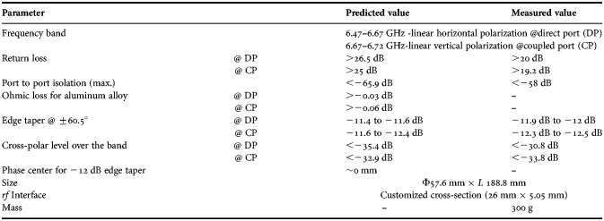
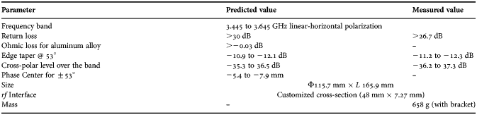
The return loss and isolation of dual-polarized receive and mono-polarized transmit feed systems is measured using a vector network analyzer (VNA) and given in Tables 1 and 2 along with the predicted results. The deviations between the measured and the predicted return loss/port-to-port isolation may be because the calibration reference of the VNA is at the coaxial port instead of the waveguide port, imperfect assembly etc. The radiation pattern is measured in an anechoic chamber. The small deviation between the measured and the predicted results may be due to measurement uncertainty, imperfect assembly and integration etc. The following subsection describes the measured/predicted and significant aspects of the transmit and receive feed systems developed.
Table 1. rf Performance of the dual-polarized receive feed system.
Table 2. rf Performance of the mono-polarized transmit feed system.

A) Dual-polarized receive feed system for lower Ext-C-Rx antenna
The measured and predicted rf performance and other details of the “compact feed system for lower Ext-C Rx antenna” are listed in Table 1.
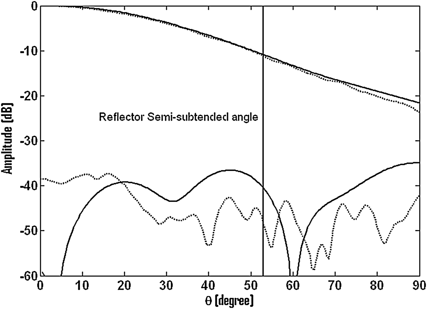
Figure 3 shows the measured and predicted co-polar and cross-polar (in D-plane) radiation patterns of the dual-polarized receive feed system for horizontally polarized communication (direct port) and vertically polarized navigation channel (coupled port). For the dual-polarized receive feed system, the outer structure of the feed (i.e. bracket for struts and tooling ball bases) has a very small/negligible effect on the cross-polar level, peak gain, and phase center and therefore, is not given here for the sake of brevity.
Fig. 3. Radiation pattern in 45°-plane (solid lines: predicted and dotted lines: measured) of lower Ext-C-Rx band feed unit (a) at direct port (6.47 GHz) and (b) at coupled port (6.67 GHz).
B) Mono-polarized transmit feed system for lower Ext-C antenna
The measured and predicted rf performance and the other details of the “lower Ext-C-Tx band feed unit for 0.9 m prime-focus reflector antenna” are given in Table 2.
Figure 4 shows the measured and predicted co-polar and cross-polar (in D-plane) radiation patterns of mono-polarized transmit feed system for horizontally polarized communication channel (through port).
Fig. 4. Radiation pattern in 45°-plane (solid lines: predicted and dotted lines: measured) of lower Ext-C-Tx band feed unit (3.445 GHz).
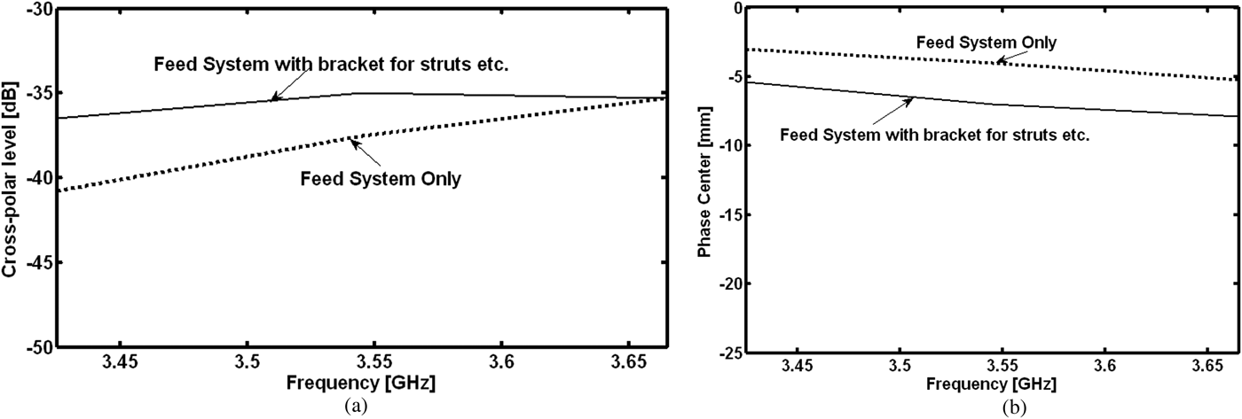
The impacts of adjustable bracket with spacer ring for struts and tooling ball bases on cross-polar level and phase center are given in Fig. 5. The bracket for the struts has a very strong effect on the cross-polar level at lower frequency (Fig. 5(a)). The outer structure (bracket, tooling ball bases etc.) has a small impact on the phase center as shown in Fig. 5(b). The outer structure of the feed has a negligible effect on the peak gain and hence is not given here for the sake of brevity. Thus, the outer structure (bracket, tooling ball bases etc.) of the feed unit may affect the cross-polar level of the reflector antenna.
Fig. 5. Impact of the outer structure of the mono-polarized transmit feed system on: (a) peak cross-level and (b) phase center.
IV. CONCLUSION
Two very compact feed units are devised and designed for high rf performance over the specified frequency band. Outer structures (such as adjustable ring and bracket for spar) deteriorate the cross-polar level of the feed system and effect on phase center of the feed, which can affect the rf performance of the reflector antenna. Thus, the correct modeling of the outer structure along with the internal cavity of the feed system is very important to predict the performance of the reflector antenna.
ACKNOWLEDGEMENTS
The authors are grateful to Mr. A.S. Kiran Kumar, Director, SAC (ISRO), Ahmedabad, Dr. J.S. Parihar, Dy. Director, EPSA, Mr. K.S Parikh, Dy. Director, SNPA, and Mr. D.K Das, Dy. Director, SNPA for his support and encouragement. The authors would like to thank Mr. V.R. Sheth, Mr. H.S. Solanki, and Mr. Indra Prakash for their assistance in measurements of feeds. The authors wish to thank the personnel at AMDD and MFF for mechanical design and manufacturing of the feeds and the components.
 Ramesh Chandra Gupta (SIEEE' 2006—MIEEE' 2008) was born in Sultanpur, Uttar Pradesh, India, in 1975. He received the B.E. degree from Shivaji University, Kolhapur, India, in 2000, the M.E. degree from RGPV University of Technology of Madhya Pradesh, Bhopal, India, in 2002, and the Ph.D. degree from the Indian Institute of Technology-Banaras Hindu University (IIT-BHU) (erstwhile IT-BHU), Varanasi, India, in 2006, all in Electronics Engineering. From February 14, 2004 to December 4, 2006, he worked at the Department of Electronics Engineering, IIT-BHU, Varanasi, India, as a Senior Research Fellow (SRF). His biography has been published in several editions of Marquis Who's who, USA and International Biographical Centre (IBC), England. He is the author of 19 journal papers and 8 conference papers. Dr. Gupta has been working at the Space Applications Centre (SAC), Indian Space Research Organization (ISRO), Ahmedabad, India, as a Scientist/Engineer-SE from July 1, 2013 with responsibility for projects concerned with the design and manufacture of horn and feed systems for satellite communications. He joined the SAC, ISRO as a Scientist/Engineer-SC on December 16, 2006. He is the Project manager for Antenna (RF) for the spacecraft GSAT-9. He has been a member of the Institution of Electrical and Electronics Engineers (MIEEE), USA since 2008. Dr. Gupta is serving as a technical reviewer for several international journals including the IEEE Transactions on Antennas and Propagation, USA and IET Microwave, antenna and propagation, UK. His current research interests include horn and shaped reflector antennas for spacecraft payload.
 Dr. Khagindra Kumar Sood was born in Sangrur, Punjab, India in 1967. He received his B.E. in Electronics & Electrical Communication Engineering from Thapar University, Patiala, Punjab, India in 1990. He received his M. E. in 1992 in Electronics & Communication Engineering from the Indian Institute of Technology (IIT Roorkee) (erstwhile University of Roorkee), Uttaranchal, India specializing in Microwave & Radar Engineering. His post-graduate work encompassed a waveguide shunt-slot feed for a microstrip patch antenna and the development of a method-of-moments code for problem analysis. He completed his Ph.D. in 2013 in Antenna & Microwave Engineering from Nirma University, Ahmedabad, Gujarat, India working on “Planar Broadband Microstrip Radiators in Conjunction with Optimum Feeding Techniques”. Since 1992 he has been with the Antenna Systems Group at the Space Applications Centre (SAC) of the Indian Space Research Organization (ISRO) at Ahmedabad, Gujarat, India. Dr. Sood has also been a Guest Scientist at the German Aerospace Centre (DLR) at Oberpfaffenhofen, Bavaria, Germany over the period 1999–2000 where he worked on technologies for active terminal antennas at Ka- and V-bands.
At ISRO, he has been involved with the design and development of antennas, feed systems, and associated passive components for spaceborne as well as ground-based applications. His key areas of interest are shaped reflectors, dual-gridded reflectors, multiple-beam antennas, unfurlable antennas, large Cassegrain earth-station antennas and feed horns, OMT's, etc. for these antennas. He has been the Deputy Project Director, Communication Payload Antennas for important ISRO communication satellite projects. In this capacity, some of his notable contributions are segmented shaped reflector for enhanced inter-beam isolation for GSAT-4, unfurlable antenna for INSAT-4E, and indigenous dual-gridded reflectors for INSAT-4G/GSAT-8. He has published some of his work in Electronics Letters, co-authored several technical papers and is an inventor/co-inventor in eight patent applications relating to antennas with high beam isolation, low cross-polarization, and multimode tracking antennas. He is currently the Division Head of the Satellite Communication Antennas Division within the Antenna Systems Group at SAC. He is responsible for the design and development of antenna systems related to satellite communications, satellite-based navigation, and satellite ground terminal antennas for various applications
 Rajeev Jyoti received his M.Sc. in Physics and M. Tech. in Microwave Electronics from Delhi University, Delhi, India in 1984 and 1986, respectively. Since 1987, he has been involved in the development of antennas for satellite communication at the Space Applications Centre (SAC), Indian Space Research Organization (ISRO), Ahmedabad, India. Presently, he is the Group Director of Antenna Systems Group at SAC, ISRO, India. He has more than 25 years experience in development of space borne and ground antennas at the SAC. He has contributed significantly in the design, analysis and development of microwave antennas namely gridded antenna, multiple beam antennas, and phased array antennas for INSAT/GSAT, RISAT, and DMSAR projects.
Mr. Rajeev Jyoti is the Fellow Member of IETE India, Senior Member of IEEE, USA, and Chair of Joint Chapter of IEEE AP and MTT, Ahmedabad. He has published more than 55 papers in various conferences and referred journals. He has 14 patents to his credit. He was awarded a UN ESA Long term fellowship in Antenna & Propagation at ESTEC/ESA, Noordwijk, Netherland.