I. INTRODUCTION
Lowpass filters (LPFs), with high performance such as ultra-wide stopband and small size, are very desirable in numerous wireless communication systems for suppression of spurious signals. One of the important factors in LPFs is a sharp transition band [Reference Hong and Lancaster1, Reference Hayati and Sheikhi2]. In [Reference Hong and Lancaster1], a compact microstrip LPF with an elliptic function response was presented. To achieve cut-off frequency response, a high equivalent capacitance and inductance between the structures of the resonator is used. A novel LPF with a very sharp transition band and wide stopband using T-shaped resonator was presented in [Reference Hayati and Sheikhi2], but circuit size of the filter is large. In [Reference Karimi, Lalbakhsh and Siahkamari3], a LPF used circular-shaped patches and open stubs to achieve sharp Roll-off and ultra-wide stopband, but it has not a symmetrical structure in its design. A miniaturized LPF with wide stopband using radial split ring resonator loaded by folded polygon patches was proposed in [Reference Hayati, Asadbeigi and Sheikhi4]. To achieve wide stopband and sharp frequency response, multiple transmission zeros by different resonator were created. Authors in [Reference Velidi and Sanyal5] presented a new structure using only transmission line elements to produce an equiripple LPF response with sharp roll-off. In [Reference Cui, Wang and Zhang6], a new microstrip LPF with compact size and an ultra-wide stopband was proposed. To achieve compact size and ultra-wide band rejection, both triangular patch resonators and radial patch resonators were adopted. A novel application of shunt open-stubs at the feed points of a center fed coupled-line hairpin resonator was proposed for the design of compact LPF with very wide stopband in [Reference Velidi and Sanyal7]. In this paper, a novel LPF with ultra-wide stopband and small size are presented. The filter has an ultra-wide stopband from 1.17 up to 13.1 GHz stopband with an attenuation level better than −20 dB. The proposed filter exhibits a small size of 0.1 × 0.092 λg, where λg is the guided wavelength at 1 GHz.
II. MAIN RESONATOR
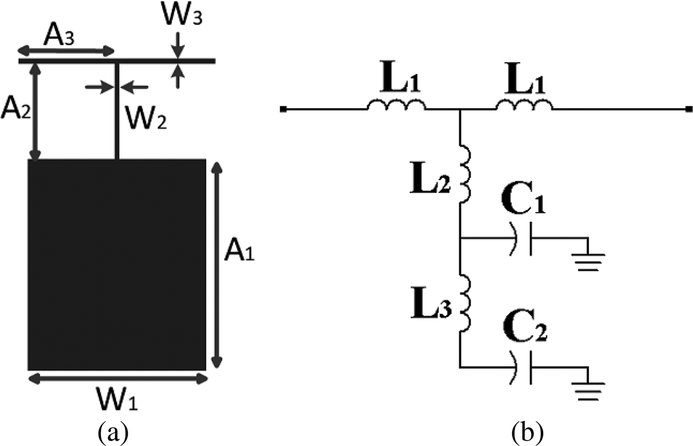
Figure 1(a) shows, the structure of main resonator. The purposed resonator for main resonator has modified T-shaped resonator in this filter. T-shaped resonators have good cut-off frequency response but they do not have wide stopband. So the other resonators are added to increase width of stopband. The parameters related to these structures are A 1 = 8.8 mm, A 2 = 4 mm, A 3 = 3.75 mm, W 1 = 7.4 mm, W 2 = 0.2 mm, and W 3 = 0.2 mm. The equivalent LC circuit of the main resonator is shown in Fig. 1(b) and L 2, L 3, and C 1 are inductance and capacitance of high-impedance lossless line. L 1 represents the inductance of the transmission line and C 2 is the sum of equivalent capacitances of open-end and high-impedance lossless line.

Fig. 1. (a) Layout of proposed resonator, (b) LC equivalent circuit.
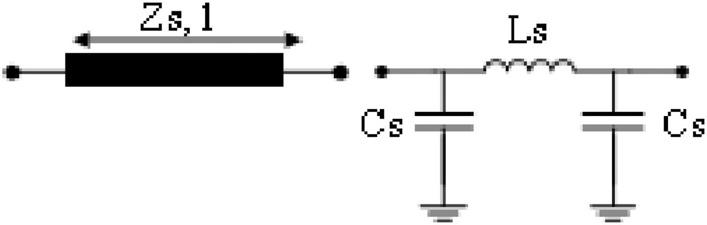
The structure of equivalent circuit includes inductances and capacitances. The values of those parameters can be extracted by the use of methods discussed in [Reference Hong and Lancaster1], A high- and low-impedance lossless line terminated at both ends by relatively low impedance lines can be presented by a Π-equivalent circuit, as shown in Fig. 2. The values of inductors and capacitors can be obtained as:
 $$l_s = \displaystyle{1 \over \omega} \times z_s \times \sin \left(\displaystyle{2\pi \over \lambda_g}l \right)\comma \;$$
 $$c_s=\displaystyle{1 \over \omega} \times \displaystyle{1 \over z_s} \times \tan \left(\displaystyle{\pi \over \lambda_g}l \right)\comma \;$$
where z s is the characteristic impedance of the line; l is the length of it; and λ g is the guided wavelength at the cut-off frequency.
Fig. 2. Layout of high- and low-impedance lossless line.
Formulas of open-end have discussed in [Reference Hong and Lancaster1]. Also structure and equivalent circuit are shown in Fig. 3.
Fig. 3. Layout of open-end.
The calculated values for LC equivalent circuit are listed in below:
L 1 = 2.37 nH, L 2 = 2.72 nH, L 3 = 0.6 nH, C 1 = 2 pF, and C 2 = 2.4 pF.
The T-shaped resonator has a transmission zero at 1.5 GHz with 50 dB attenuation level. The transmission zero is important because sharp transition band and cut-off frequency is controlled with the transmission zero. There are a few methods for computation of transmission zero. We used LC equivalent circuit and transformation function for the computation of the transmission zero. Figure 4 shows the frequency response of the main resonator and LC equivalent circuit, also transmission zero have demarcated in this figure.
Fig. 4. Frequency response of the main resonator and LC equivalent circuit.
Transformation function is extracted from LC circuit as
 $$\displaystyle{v_o \over v_i} = \displaystyle{r \over 2 + C_2\, s} \times \displaystyle{\lpar 1 + C_1\, L_2 + C^2 \lpar L_2 + L_3 \rpar \rpar s^2 + C_1 C_2\, L_2\, L_3\, s^4 \over \lpar r + \lpar L_1 + 2\lpar L_2 + L_3 \rpar \rpar s + C_1\, s\lpar r + \lpar L_1 + 2L_2 \rpar s\rpar \lpar 1 + C_2\, L_3\, s^2 \rpar \rpar}\comma$$
r in equation (3) refers to the resistance of matching. The transmission zero can be calculated using the transformation function in (3) as
 $$T_z = \sqrt{\textstyle{1 \over 8\Pi^2 c_1}} \times \sqrt{\displaystyle{1 \over L_2} + \displaystyle{1 \over L_3} + \displaystyle{C_1 \over C_2\, L_3} - \displaystyle{\sqrt{- 4C_1 C_2\, L_2\, L_3 + \lpar C_1\, L_2 + C_2\, L_2 + C_2\, L_3 \rpar^2} \over C_1 C_2\, L_2\, L_3}}.$$
III. DESIGN OF LPF
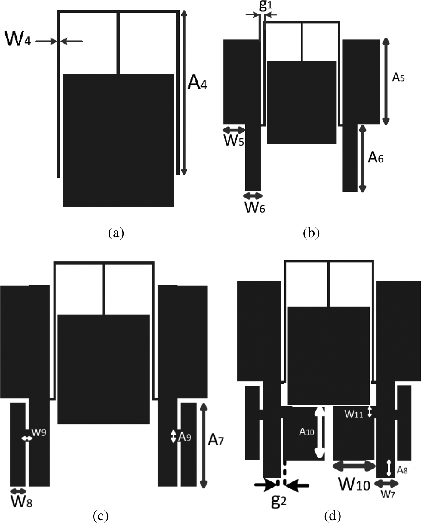
The design process of the filter is shown in Fig. 5. Figure 5(a) shows T-shaped resonators. There are two dip at 4.8 and 6.9 GHz. L-shaped resonators in Fig. 5(b) is added to achieve wide stopband and to eliminate the dips. Fig. 5(b) shows both L-shaped resonators added to T-shaped for increasing stopband width and sharp transition band. Figs 5(c) and 5(d) show both T- and L-shaped resonators used in the filter for extending stopband width, because they can generated transmission zeroes for increasing stopband width. Cut-off frequency and transmission zeroes can be adjusted with changing dimensions, for example transmission zeroes at 6.2 and 9.4 GHz can be changed with g1 and also cut-off frequency can be changed with A 1.
Fig. 5. Microstrip layout of (a) modified T-shaped resonator, (b) both L-shaped resonators added to T-shaped, (c) added T-shaped, and (d) added L-shaped.
The correlative parameters in Fig. 5 are: A 4 = 11.1, A 5 = 9, A 6 = 7.1, A 7 = 6.7, A 8 = 1.5, A 9 = 0.3, A 10 = 4.8, W 4 = 0.2, W 5 = 2.3, W 6= 1.6, W 7 = 1.17, W 8 = 1.2, W 9 = 0.3, A 10 = 3.7, g 1 = 0.3 and g 2 = 0.25 (all in millimeters). Figures 6(a)–(d) show frequency responses of each resonator.
Fig. 6. Frequency response of (a) Modified T-shaped resonator, (b) both L-shaped resonators added to T-shaped, (c) added T-shaped, and (d) added L-shaped.
IV. SIMULATION AND MEASUREMENT RESULTS
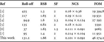
The photograph for the proposed filter is shown in Fig. 7(a). This filter fabricated on a 20 mil thick RO4003 substrate with a relative dielectric constant 3.38 and loss tangent of 0.0021. By detecting the Fig. 7(b), it is obvious that the realized filter has very sharp transition band about 0.21 GHz (1.028–1.19 GHz with −3 and −20 dB, respectively). Also a return loss of better than 11 dB and an insertion loss of less than 0.5 dB from DC to 0.85 GHz are achieved. Measurement results show ultra-wide stopband stretched from 1.19 to 13 GHz with 20 dB attention level. The overall size of the fabricated LPF is about 18.1 × 16.6 mm2, which corresponds to an electrical size of 0.101 λg × 0.092 λg, where λg is the guided wavelength at 1 GHz. Table 1 gives the performance of some LPFs.
Fig. 7. (a) Photograph of the proposed filter, (b) simulated and measured S-parameters of the proposed LPF.
Table 1. Performance comparisons between published filters and the one proposed in this paper.
For comparison, Table 1 provides a breakdown of some LPF performance where the roll-off rate is defined as:
 $$\xi=\displaystyle{\alpha_{max} - \alpha_{min} \over f_s - f_c} \lpar {\rm dB}/{\rm GHz}\rpar \comma \;$$
where α max is the 40 dB attenuation point, α min is the 3 dB attenuation point, f s is the 40 dB stopband frequency, and f c is the 3 dB cut-off frequency. The relative stopband bandwidth (RSB) is given by:
 $$RSB=\displaystyle{{\rm Stopband}\, {\rm bandwidth} \over {\rm Stopband}\, {\rm center}\, {\rm frequency}}.$$
The suppression factor (SF) is based on the stopband bandwidth. For example, the stopband bandwidth is referred to 20 dB suppression, thus the corresponding SF is defined as 2. A higher suppression corresponds to a greater SF.
 $$SF = \displaystyle{{\rm Attenuation}\,{\rm level} \over 10}.$$
The normalized circuit size (NCS) is calculated by:
 $$NCS=\displaystyle{{\rm Physical}\,{\rm size}\, \lpar {\rm length} \times {\rm width} \rpar \over \lambda_g^2}\comma \;$$
where λ g is the guided wavelength at 3 dB cut-off frequency. Finally, the figure-of-merit (FOM), the overall index of a proposed filter, is given by:
 $$FOM = \displaystyle{\xi \times {\rm RSB} \times {\rm SF} \over {\rm NCS} \times {\rm AF}}.$$
As can be seen from Table 1, it clearly shows that the designed filter is superior to those reported in references, specially, in FOM which is more than twice and NCS is smaller than the other works.
V. CONCLUSION
A LPF with 1.02 GHz cut-off frequency using the modified T-shaped resonator has been advised, fabricated, and measured. The proposed LPF has exhibited many desirable features, such as ultra-wide stopband, sharp characteristic, and compact size. The presented filter has many eligible features, in terms of compact size, sharp transition band, and wide stopband in comparison with other works. With all these good features, the proposed filter is applicable for modern communication systems.
Behnam Afzali was born in Kermanshah, Iran in 1988. He received his B.Sc. degree in Electronic Engineering in 2010 from Islamic Azad University, Kermanshah Branch in Iran; also he received his M.Sc. degree in Electronic Engineering in 2014 from Islamic Azad University, Science and Research Branch in Iran. His current research interests are RF/Microwave circuit design.
 Mohammad Mehdi Karkhanehchi was born in Kermanshah-Iran. He received his B.Sc. degree in Physics from Razi University in 1977 and received his M.Sc. degree in Electrophysics (with honor) from George Washington University in the USA in 1980. Then, he was employed as an instructor in Razi University until 1992. He continued his education as Ph.D. student in Glasgow University in UK and received his Ph.D. degree (with honor) in 1996. Now, he is an Assistant Professor in the Faculty of Engineering in Razi University. His research interests are in design, fabrication of semiconductor optical waveguides and design, simulation of photonics crystal. He is the author and co-author of many journals and conference papers. Also, he published three books.
 Gholamreza Karimi was born in Kermanshah, Iran in 1977. He received the B.S. and M.S. and Ph.D. degrees in Electrical Engineering from Iran University of Science and Technology (IUST) in 1999, 2001 and 2006, respectively. Currently he has been an Assistant Professor in Electrical Department at Razi University, Kermanshah, since 2007. His research interests include low-power analog and digital IC design, RF IC design, modeling and simulation of RF-mixed signal IC and microwave devices and artificial intelligence systems.