Introduction
The state-of-the-art compact laser technologies have made laser wakefield acceleration (LWFA) scheme (Tajima and Dawson, Reference Tajima and Dawson1979; Leemans et al., Reference Leemans, Nagler, Gonsalves, Toth, Nakamura, Geddes, Esarey, Schroeder and Hooker2006; Hafz et al., Reference Hafz, Jeong, Choi, Lee, Pae, Kulagin, Jung, Yu, Hong, Hosokai, Cary, Ko and Lee2008; Esarey et al., Reference Esarey, Schroeder and Leemans2009), an excellent and powerful tool for industrial, medical, and other applications. The interaction of short and intense laser pulse with plasma drives a plasma wave (Kaur and Gupta, Reference Kaur and Gupta2016) that can trap and accelerate the electrons to relativistic energy over centimeter scales. The dynamics of accelerated electron bunch is determined by the properties of laser and plasma density. The high acceleration gradient, low-cost, and table-top size as compared with RF-based accelerators have enabled LWFA scheme, a promising technology for next-generation accelerators and compact radiation sources (Jaroszynski et al., Reference Jaroszynski, Bingham, Brunetti, Ersfield, Gallacher, Van Der Geer, Isaac, Jamison, Jones, De Loos, Lyachev, Pavlov, Reitsma, Saveliev, Vieux and Wiggins2006; Nakajima, Reference Nakajima2008; Albert et al., Reference Albert, Thomas, Mangles, Banerjee, Corde, Flacco, Litos, Neely, Vieiria, Najmudin, Bingham, Joshi and Katsouleas2014).
One of the most important issues in LWFA is the quality and stability of the electron beam. The energy gain, emittance, and spread of accelerated electron bunch are regulated by the longitudinal and transverse injection mechanism of electrons (Dawson, Reference Dawson1959; Faure et al., Reference Faure, Glinec, Pukhov, Kiselev, Gordienko, Lefebvre, Rousseau and Malka2004; Geddes et al., Reference Geddes, Toth, Tilborg, Esarey, Schroeder, Bruhwiler, Nieter, Cary and Leemans2004; Mangles et al., Reference Mangles, Murphy, Najmudin, Thomas, Collier, Dangor, Divall, Foster, Gallacher, Hooker, Jaroszynski, Langley, Mori, Norreys, Tsung, Viskup, Walton and Krushelnick2004; Tsung et al., Reference Tsung, Narang, Mori, Joshi, Fonseca and Silva2004). Various methods have been proposed for injecting electrons into the wakefield including density transition (Schimd et al., Reference Schimd, Buck, Sears, Mikhailova, Tautz, Herrmann, Geissler, Krausz and Veisz2010) or density downramp injection (Hansson et al., Reference Hansson, Aurand, Davoine, Ekerfelt, Svensson, Persson, Wahlstrom and Lundh2015), ionization-induced injection (Yu et al., Reference Yu, Esarey, Schroeder, Vay, Benedetti, Geddes, Chen and Leemans2014), colliding optical injection (Davoine et al., Reference Davoine, Lefebvre, Rechatin, Faure and Malka2009). But the self-injection scheme is preferred more in designing the accelerators as there is no need for external injector. The self-injection mechanism in bubble regime of LWFA offers a possibility in generating high-energy electron beam and has been investigated theoretically (Kostyukov et al., Reference Kostyukov, Nerush, Pukhov and Seredov2009; Benedetti et al., Reference Benedetti, Schroeder, Esarey, Rossi and Leemans2013; Lee et al., Reference Lee, Lee, Gupta, Uhm and Suk2015) and experimentally (Hafz et al., Reference Hafz, Lee, Jeong and Lee2011; Banerjee et al., Reference Banerjee, Kalmykov, Powers, Golovin, Ramanathan, Cunningham, Brown, Chen, Ghebregziabher, Shadwick, Umstadter, Cowan, Bruhwiler, Beck and Lefebvre2013) in recent years.
Pukhov and Meyer-ter Vehn (Reference Pukhov and Meyer-Ter Vehn2002) presented the self-injection of electrons in the bubble regime of laser wakefield using particle-in-cell (PIC) simulations. The bubble regime of laser wakefield accelerator is characterized by an ultrashort laser pulse with a 0 ≥ 4 and pulse length shorter than the plasma wavelength 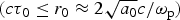 $(c{\rm \tau} _0 \le r_0 \approx 2\sqrt {a_0} c/{\rm \omega} _{\rm p})$, where τ0, r 0, and a 0 are laser pulse duration, spot size, and normalized vector potential, respectively, and ωp and c are plasma frequency and speed of light, respectively. Using three-dimensional (3D)-PIC simulations, Lu et al. (Reference Lu, Tzoufras, Joshi, Tsung, Mori, Vieiria, Fonseca and Silva2007) have shown that the LWFA in bubble regime can be operated even if 2 ≤ a 0 ≤ 4, where the bubble radius (R) matches with the spot size of the laser pulse such that
 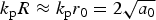 $k_{\rm p}R \approx k_{\rm p}r_0 = 2\sqrt {a_0} $ (where k p is the plasma wave number). The ponderomotive force of ultrashort laser pulse expels the plasma electrons, leaving ions behind and forming a cavity devoid of electrons called “bubble”. This bubble is demonstrated as 3D plasma wave trailing behind the laser pulse that moves at relativistic speeds. The electric field due to charge separation will trap the electrons at the back of the bubble and accelerate them to higher energy. These electrons can outrun the plasma wave and move into a decelerating region to lose energy. Theoretically, it has been observed that the evolution of bubble structure determines the quality of the accelerated electron bunch (Kalmykov et al., Reference Kalmykov, Beck, Yi, Khudik, Downer, Lefebvre, Shadwick and Umstadter2011; Li et al., Reference Li, Yu, Gu, Huang, Kong and Kawata2015; Toosi et al., Reference Toosi, Mirzanejhad and Dorronian2016).
To improve the electron bunch quality, it is important to control the laser as well as the plasma parameters, improve the diagnostic techniques, and improve the total acceleration distance, which is limited by diffraction, depletion, and dephasing length. Extension of laser–plasma interaction length has been achieved through the combination of performed plasma channel guiding, relativistic self-focusing, and ponderomotive self-channeling to mitigate the problem of diffraction (Sprangle et al., Reference Sprangle, Esarey and Krall1996; Kaur et al., Reference Kaur, Gupta and Suk2017). Self-guiding provides stability to the bubble evolution, and hence controls the self-injection enabling the production of extremely high-quality electron bunch (Kalmykov et al., Reference Kalmykov, Beck, Yi, Khudik, Shadwick, Lefebvre and Downer2010). One of the major limitations in achieving monoenergetic electron beam in LWFA is dephasing between plasma wave and electron beam due to the difference between the velocity of accelerated electrons and the phase velocity of the wakefield. The length over which the electron travels before it gets decelerated is called the dephasing length. The dephasing length limitation can be mitigated by lowering the plasma density, but sufficient plasma density is required for self-injection to occur.
The profile of plasma density is very important in LWFA experiments and it should be considered in a way to synchronize for the accelerated electron corresponding to the phase velocity of the bubble. The dephasing length in bubble regime (L d) is calculated from the phase velocity of the plasma wave (υφ) and the bubble radius (R) as L d = R/(1 − υφ/c). Katsouleas (Reference Katsouleas1986) was the first to propose a way to overcome the dephasing limitation by tailoring the plasma density, commonly referred as plasma tapering. The tapering mechanism to phase lock a relativistic particle by the accelerating (longitudinal field) and focusing (transverse field) forces have been studied theoretically by Rittershofer et al. (Reference Rittershofer, Schroeder, Esarey, Gruner and Leemans2010). Bulanov et al. (Reference Bulanov, Naumova, Pegoraro and Sakai1998) performed 1D-PIC simulations of a laser pulse with propagating in a downward plasma density ramp and found that the plasma wave breaks on the ramp and injects a significant number of electrons. Albeit, the electrons are accelerated to high energy, but the energy spread of the electron bunch is very large. Kim et al. (Reference Kim, Kim and Yoo2011) simulated the effect of upward plasma density ramp on energy gain of electrons through a 2D-PIC code for a 20 TW laser and observed that, in case of upward plasma density ramp, the acceleration region moves faster as compared with the downward ramp and uniform plasma density. The plasma wave generates a higher accelerating gradient to generate an energetic electron bunch. Yu et al. (Reference Yu, Gu, Li, Huang, Kong and Kawata2015) has theoretically analyzed the phase velocity of wakefield and estimated the threshold required to achieve the self-injection by introducing linear up-ramp plasma density gradient and verified it using PIC simulations. However, the scaling laws for the plasma density ramp still need to be investigated to optimize the bubble parameters to estimate the electron energy gain.
The strong ponderomotive force of a high-intensity laser pulse (a 0 ≥ 4) interacting with an underdense plasma  $({\rm \omega} _{\rm p}^2 \lt \lt {\rm \omega} ^2)$ expels all the electrons, creating an ion cavity called the bubble, with electrons acting as sheath boundary. The plasma electrons at the rear of the bubble get self-injected and accelerated due to the corresponding longitudinal electric field of the bubble. These electrons gain energy while propagating with the velocity close to the speed of light. For highly non-linear regime, the phase velocity of a plasma wave is calculated from the laser pulse front velocity considering the laser pulse depletion effect. In case of uniform plasma, the bubble velocity at the front and rear remains same throughout, which is equal to the phase velocity of the plasma wave, i.e. υφ ≈ υg − υetch ≈ c(1 − 3n e/2γn c), where υg = c(1 − n e/2γn c) is the group velocity of laser pulse, and υetch ≈ n e/γn c is the etching velocity due to laser pulse depletion. n e and n c are the plasma density and the critical density, respectively, and
 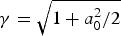 ${\rm \gamma} = \sqrt {1 + a_0^2 /2} $. The accelerated electron will get out of the phase after traveling a certain distance called dephasing length. The difference in the velocities of plasma wave and accelerated electron accounts for dephasing. In order to suppress dephasing, a positive linear-upward density profile is introduced in this proposal such that the bubble shrinks leading to difference in the front and back velocities of the bubble.
In this paper, we examined the improvement in dephasing length and energy gain of the accelerated electrons by introducing a linear-upward density ramp structure in bubble regime of LWFA by performing 2D-PIC simulations using VORPAL code (Nieter and Cary, Reference Nieter and Cary2004). We have considered upward plasma density ramp with different ramp lengths followed by a uniform density region and measured the effect of density ramp length on the phase velocity of bubble wake leading to an increase in dephasing length and energy gain of the accelerated electrons. We have elucidated the physics of dephasing length in bubble regime to study its dependence on the linear-upward plasma density distribution. The 2D-PIC simulations have been proposed to investigate the effect of linear-upward density profile on dephasing length and energy gain followed by the conclusion.
Two-dimensional PIC simulations
We have performed 2D-PIC simulations using VORPAL simulation code to optimize the dephasing length and the electron energy gain by considering linear-upward plasma density profile. A linearly polarized laser pulse propagates along x-direction with a transverse electric field of  ${\bf E} = {\mathop{z}\limits^{\frown}} E_0\exp ( - x^2/L_{{\rm rms}}^2 )\exp ( - r^2/r_0^2 )\cos (\omega t - kx)$ in a plasma of length of 1500 µm. The full width at half maximum (FWHM) laser pulse τ0 is related as
 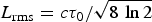 $L_{{\rm rms}} = c{\rm \tau} _0/\sqrt {8\,\ln 2} $. The laser pulse strength is a 0 = 5 with the wavelength of λ = 0.8 μm, the spot size of r 0 = 9 μm, and the pulse duration of τ0 = 30 fs (FWHM). The focus of laser pulse is fixed in the middle of the density ramp. The plasma density profile is defined over a distance with different upward density ramp length ranging from 0 to 700 μm over which the density is increased from 0 to n e = 4 × 1025 m−3 followed by a flat density plateau such that the total plasma length is the sum of the ramp and flat length. A moving window is used for simulation with window size resolved in x- and y-directions with grid size λ/30 and λ/4, respectively. The number of particles per cell used for simulations is four. The laser and plasma parameters are not exactly matched to the resonant condition of bubble regime in our simulations, but these are optimized for sufficient self-injection of the particles at the rear of the bubble to accelerate to higher energies. The evolution of laser pulse and coupling between the interacting waves has been neglected in this study. This may be justified by the fact of highly non-linear system (a 0 > 4) and, of course, the exact physics would also be really difficult to explore in that scenario. We have also performed simulations for a uniform plasma density case (i.e. no plasma density ramp). The results of this case have been compared with the case of plasma density ramp.
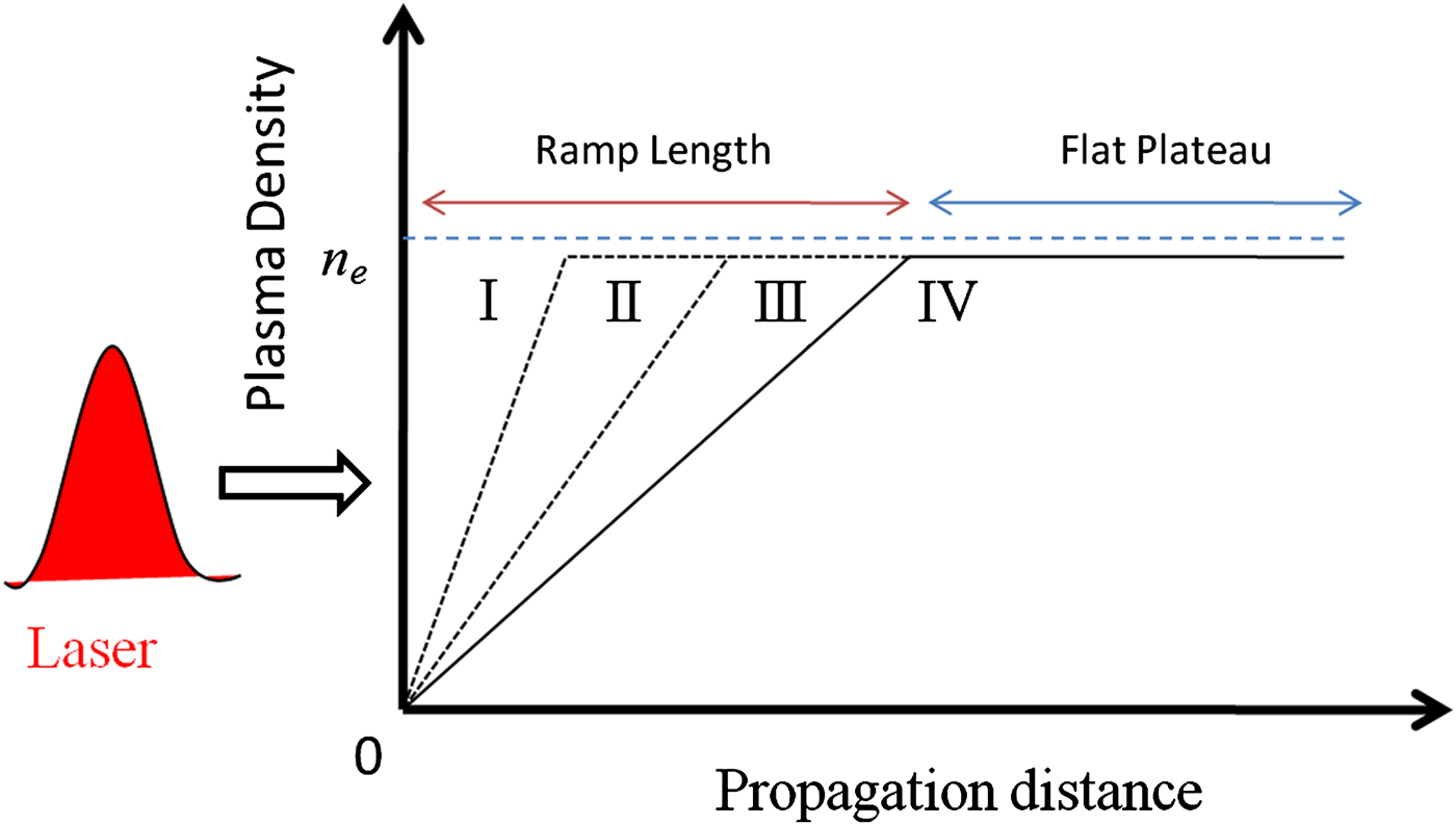
The schematic diagram of plasma density profile is shown in Figure 1 for four different cases by considering the flat density with no ramp, i.e. d r = 0 (case I), upward ramp length of d r = 300 μm (case II), d r = 500 μm (case III), and d r = 700 μm (case IV). In all these cases, the density increases linearly from 0 to n e for 0 ≤ x ≤ d r and then remains constant at n e = 4 × 1025 m−3 for d r ≤ x ≤ 1500 μm. This kind of plasma density profile can be generated experimentally using a capillary gas cell and controlled by sending the gas with varying pressures at two inlets (Kim et al., Reference Kim, Lee, Kim, Nam and Suk2016). The gas density is increased from the capillary entrance by changing the pressure of the first inlet such that the density gradient is created along the capillary axis from the entrance to intersection of the capillary and second inlet, keeping a constant pressure.

Fig. 1. Schematic representation of linear-upward plasma density distribution used in PIC simulation with ramp length (d r) varied for four different cases: without ramp d r = 0 (case I), and with ramp d r = 300 μm (case II), d r = 500 μm (case III), and d r = 700 μm (case IV). The plasma density ramp is followed by the flat density plateau with a total plasma length of 1500 μm.
An ion cavity (or bubble) is created due to the ponderomotive force of the laser pulse that expels all the electrons. The field generated in the bubble exerts the force on some of the unshielded electrons for self-injection to occur. These self-trapped electrons will undergo the process of acceleration to increase their energy. We have compared the contour plot of charge density distribution showing the formation of bubble and the self-injection of particles in Figure 2a–2d at same time t = 1.8 ps for all four cases. We have chosen the observation point at t = 1.8 ps to compare the evolution of bubble in all cases. The corresponding maximum energy gain of the accelerated electrons is shown in Figure 2e–2h. In case I (Fig. 2a), a stable bubble is formed after laser has propagated a distance of about 230 μm and the electrons are self-injected in the bubble. These self-injected electrons are accelerated continuously to a maximum energy of 0.16 GeV before these electrons outrun the plasma wave (Fig. 2e). The bubble structure elongated during the acceleration of self-injected electrons. A stable bubble is formed after density transition in case II. The acceleration of self-injected electrons after the formation of bubble and the corresponding energy gain of continuous accelerated electron beam are shown in Figure 2b and 2e, respectively. During the density transition, the plasma wavelength increases. When the laser pulse interacts with inhomogeneous plasma, the group velocity of the laser pulse is modified due to its dependence on the plasma wavelength. Consequently, the corresponding phase velocity of the wakefield and the radius of the bubble structure are also modified. The electrons accumulated at the back of the bubble are self-injected and accelerated to higher energies after attaining a certain threshold (Yu et al., Reference Yu, Gu, Li, Huang, Kong and Kawata2015). In case III (Fig. 2c), the bubble starts evolving at the end of ramp at 500 μm, where the electrons self-inject at the back of the bubble. These self-injected electrons are accelerated continuously to achieve maximum energy gain before they get decelerated. At time t = 1.8 ps, the bubble is fully evolved in cases I, II, and III. However, the same is not observed for case IV (Fig. 2d), where the ramp length is much larger (700 μm). During the density transition along the ramp length, the size of the bubble structure decreases and the self-injection does not occur. The density gradient should be sharp enough in order to modify the phase velocity of the bubble for self-injection to occur.
Fig. 2. Contour plot of charge density distribution (a–d) and maximum energy gain of accelerated electrons (e–h) in the case of linear-upward density profile with no ramp, and ramp length 300 μm, 500 μm, and 700 μm for a 0 = 5 at time t = 1.8 ps.
The energy gain of the accelerated electrons is sensitive to the length of plasma density ramp. A stable bubble is formed after the laser has traversed a distance equal to the density ramp length. Beyond this length, the bubble elongates in the longitudinal direction and the phase velocity of the back part of the bubble increases. The self-injected electrons are continuously accelerated as the phase velocity of the bubble synchronizes with the accelerated electron velocities. Consequently, the electrons gain higher energy during this process. The energy of electrons is enhanced with the dephasing length over which the electrons are accelerated.
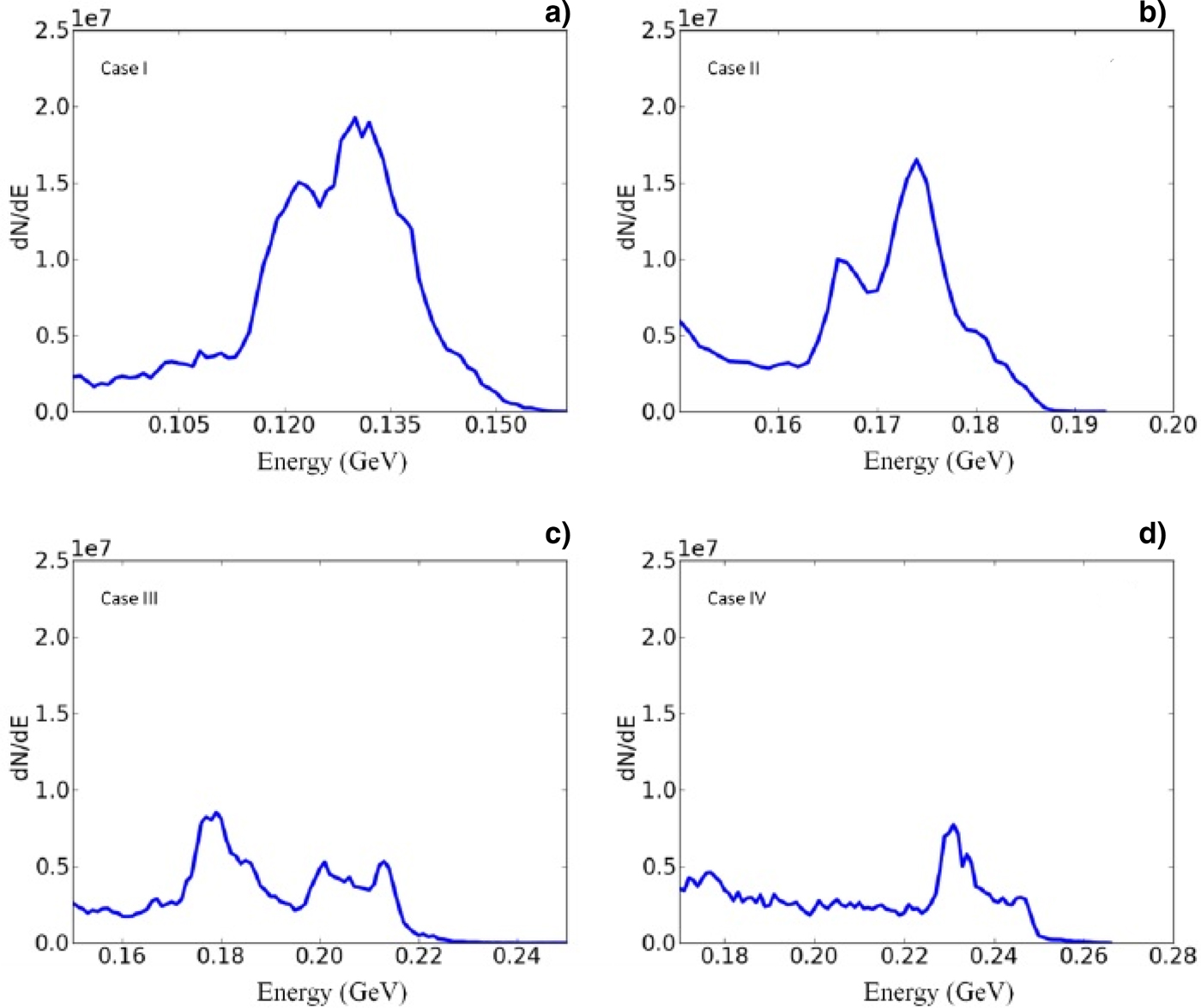
For many applications, it is desirable to generate mono-energetic high-quality accelerated electron beam from the accelerators. Therefore, it is important to study the energy spectra of self-injected accelerated electrons. The energy spectrum of the accelerated electrons for all cases shown in Figure 3 is not mono-energetic due to the continuous injection of electrons. It has been previously studied that the self-focusing of the laser pulse results in the elongation of the bubble and improved self-injection of the electrons (Kim et al., Reference Kim, Kim, Kim, Ko, Lee and Suk2003). The evolution of bubble structure can be controlled by employing a density gradient in such a way that results in limiting the number and energy spread of the injected electrons. It can be predicted from the results that the peak energy gained by the number of particles is higher in case of plasma density ramp profile as compared with the case of flat density profile.

Fig. 3. Electron energy spectrum with different plasma density distribution for (a) flat density profile, (b) the plasma density ramp length of 300 μm, (c) the plasma density ramp length of 500 μm, and (d) the plasma density ramp length of 700 μm.
The energy spectra of the electrons having peak energy of 0.12 GeV, when a flat density distribution is considered, is not enviable for many applications. It is shown that the energy spread is reduced by employing an upward plasma density gradient in a plasma. This may be because the number of self-injected electrons increases due to enhanced self-focusing of laser pulse when a positive density gradient is considered over an upward ramp with a typical scale length of 3R d0 (Rayleigh length) (Gupta et al., Reference Gupta, Hur, Hwang, Suk and Sharma2007). In our results, the electron beam is better collimated with a peak energy of 0.2 GeV (almost double) if a density ramp length of 700 μm is introduced. This is because of the reason that the ratio of longitudinal to transverse velocity of electrons is higher in this case. The accelerated electrons have both longitudinal and transverse velocities. The electrons, thus, are synchronized with the plasma wave resulting in a highly collimated electron beam. It has been observed in a number of simulations that if the ramp length (d r) is larger than 500 μm, the electrons are self-injected before it reaches the maximum plasma density. This can be attributed to the fact that the threshold to achieve self-injection in non-linear regime varies for different plasma density distribution as the phase velocity of the bubble modifies with the plasma density profile. So, it is important to choose the upward plasma density gradient appropriately for self-injection of electrons in LWFA.
The size of the bubble is a function of laser pulse intensity and plasma density. When an upward density ramp is introduced, the bubble shrinks with velocity  ${\rm \upsilon} _{{\rm sh}} = - {\rm \lambda} \,(d\sqrt {{\rm \gamma} n_{\rm c}/n_{\rm e}} /dx){\rm \upsilon} _{\rm b}$, where x and υb are the position and back velocity of the bubble and λ is the laser pulse wavelength (Decker and Mori, Reference Decker and Mori1994; Wen et al., Reference Wen, Shen, Zhang, Wang, Jin, Ji, Wang, Xu and Nakajima2010). The front velocity is same as the laser pulse group velocity. So, the bubble back velocity in terms of plasma density gradient can be expressed as
  ${\rm \upsilon} _{\rm b} = {\rm \upsilon} _{{\rm sh}} + {\rm \upsilon} _{\rm \varphi} \approx c(1 - 3n_{\rm e}/2{\rm \gamma} n_{\rm c})/(1 + {\rm \lambda} \left( {\sqrt {{\rm \gamma} n_{\rm c}} /n_{\rm e}^{3/2}} \right)dn_{\rm e}/dx).$ This equation implies that the bubble back velocity increases with the plasma density to synchronize with electron velocity. Reversely, the front velocity of the bubble decreases due to pulse depletion.
In Figure 4, the charge density distribution showing the evolution of bubble structure and the corresponding energy gain of the accelerated electrons are observed at three different times t = 1.7 ps, 2.3 ps, and 2.7 ps, where a plasma density gradient with a ramp length of 500 μm has been used. Initially, when a stable bubble is formed at the end of ramp length, the self-injected electrons get accelerated to only a few MeV (Fig. 4a and 4d). The bubble structure shrinks during the density transition region. When the laser has surpassed the ramp length and comes in the flat density region, the bubble excited by laser pulse elongates along the longitudinal direction as shown in Figure 4c. The change in the size of the bubble increases the back phase velocity while front velocity of bubble remains same. This assists more number of electrons to attain the self-injection threshold and thus a continuous acceleration may be reasonable to higher energies of the electrons. The maximum electron energy achieved in this case is about 0.24 GeV (Fig. 4f). The electrons get out of phase after traveling an acceleration distance equal to the dephasing length and lose energy as they enter the decelerating region.
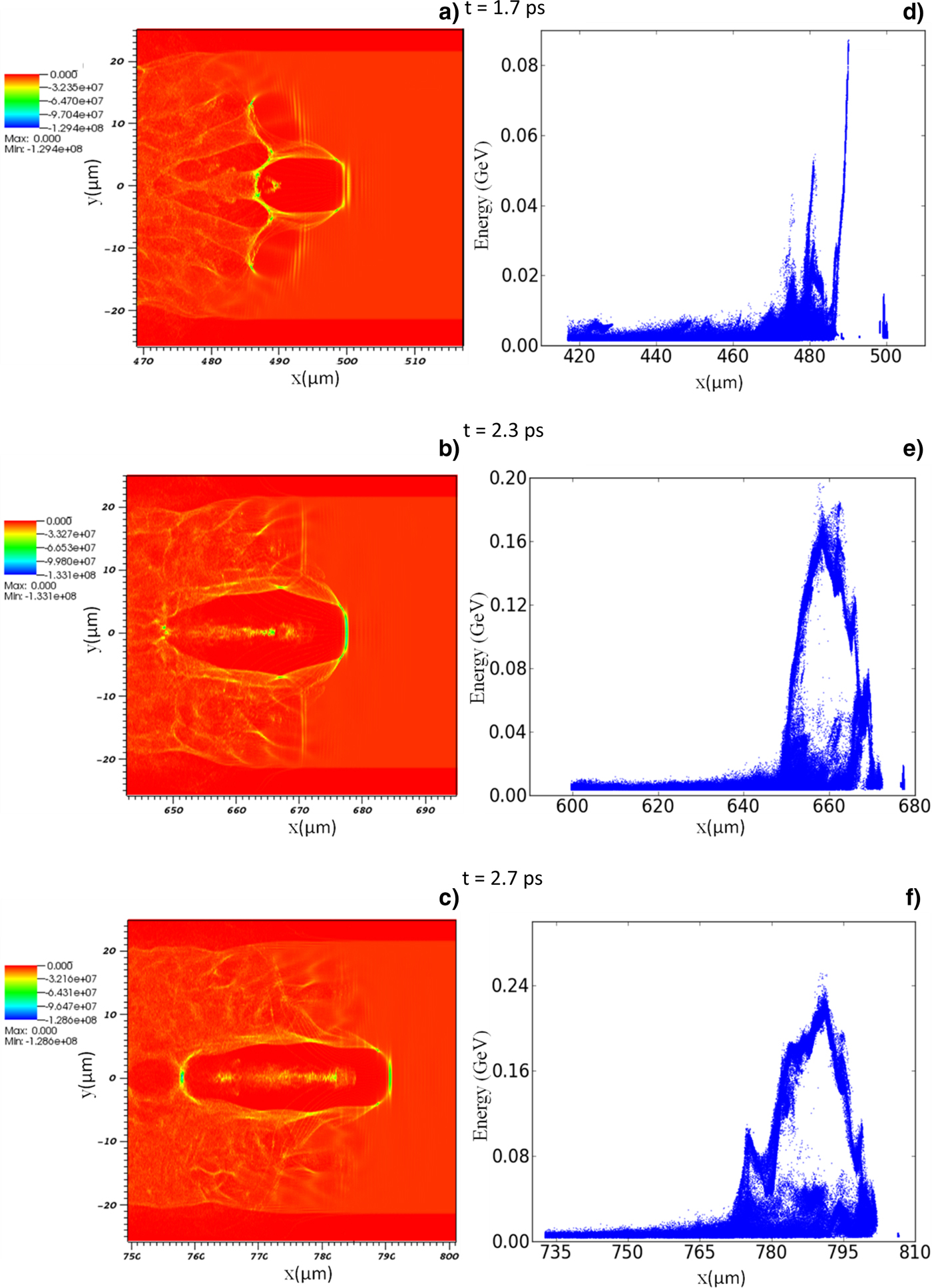
Fig. 4. Contour plot of charge density distribution (a–c) and corresponding energy gain of accelerated electrons (d–f) for upward density gradient plasma with ramp length of 500 μm at three different time steps t = 1.7 ps, 2.3 ps, and 2.7 ps.
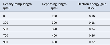
In Table 1, using 2D-PIC simulations, we have tabulated the values of maximum dephasing length and the corresponding electron energy gain achieved in bubble regime of LWFA by employing different plasma density gradients with varying ramp lengths.
Table 1. Dephasing length and electron energy gain optimization using PIC simulations

Enhancement in dephasing length and maximum energy achieved by the accelerated electrons with the ramp length of linear-upward density profile has been presented in Figure 5. When the flat density distribution of the plasma is considered, the dephasing length is about 290 μm, which is in close agreement with the calculated theoretical value for these laser and plasma parameters (Nakajima et al., Reference Nakajima, Kim, Jeong and Nam2015). When a linear-upward density profile is introduced at the beginning of plasma such that the density increases from 0 to n e = 4 × 1025 m−3 over a distance equal to the ramp length (d r), the dephasing length is extended over larger distances. For highly non-linear regime (a 0 = 5), the length over which electrons get accelerated to higher energy is also extended due to an increase in dephasing length. The energy gain of the accelerated electrons is scaled with dephasing length. Hence, the energy gain is also enhanced by employing a linear up-ramp plasma density profile. For a plasma density profile with a ramp length of 900 μm, the dephasing length is extended to 430 μm and the corresponding maximum energy gain of the accelerated electrons is about 0.32 GeV.
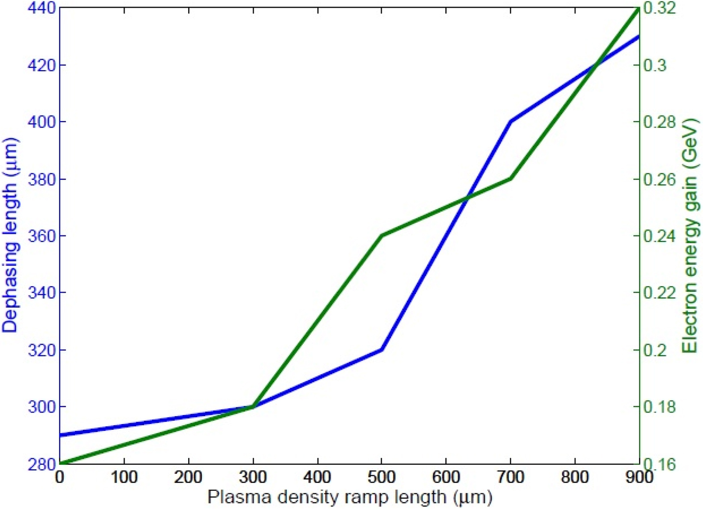
Fig. 5. Dephasing length (blue) and electron energy gain (green) with the ramp length (μm) for a 0 = 5, r 0 = 9 μm, and τ0 = 30 fs.
Conclusion
In order to study the effects of plasma density distribution on dephasing length and accelerated electrons energy gain in bubble regime of laser wakefield accelerators, 2D-PIC simulations have been performed. We have optimized the laser and plasma parameters for sufficient self-injection of electrons in LWFA. The dephasing length limits the energy gain of accelerated electrons by reducing the acceleration length. The self-injected electrons get trapped and are accelerated to higher energies over a distance equal to the dephasing length until the electrons remain in phase with the plasma wave. After that distance, the electrons enter into the decelerating region and lose energy. In case of flat plasma density distribution, the maximum electron energy gain is about 0.16 GeV. In order to extend the dephasing length over longer distances, we have introduced a linear-upward density profile with different ramp length (d r), over which the electron density starts from zero and attains a maximum value n e = 4 × 1025 m−3 and then remains constant for the rest of the plasma region. It was observed that the dephasing length is extended over larger distances by considering the linear-upward density profile. The dephasing is generated because of the difference in the accelerated electron velocity and the phase velocity of the bubble. The front velocity of bubble matches with the laser pulse front velocity, while the back velocity of the bubble is increased during the density transition due to its dependence on plasma density gradient such that it synchronizes with the electrons moving with relativistic velocities. After the density gradient region, the bubble structure elongates in the longitudinal direction and an electron beam with enhanced energy gain due to extended dephasing length was observed. The energy gain of accelerated electrons is about 0.26 GeV in case of linear-upward plasma density profile of a ramp length of 700 μm. The energy spread of the accelerated electrons is also reduced by increasing the ramp length, since the number of self-injected electrons attaining threshold increases with larger longitudinal velocities. The energetic electron beam is more collimated in the case of linear-upward density profile. This study may be crucial in understanding the role of plasma density profile to enhance the accelerated electron energy and controlling the electron beam collimation in bubble regime of LWFA.
Acknowledgement
This work was supported by the Department of Science and Technology, Govt. of India under DST-RFBR joint research proposal (Grant No. INT/RUS/RFBR/P-186).