


1. Introduction
Fan noise is a major contributor to the total noise emission of turbofan engines at both take-off and landing. The decreasing nacelle length and increasing fan diameter of modern high-bypass turbofan engines further escalate the noise reduction challenge to acoustic treatment designs. One of the bold attempts – breaking the limitation on conventional liner location due to aerodynamic and structural considerations – is to place acoustic lining in the immediate proximity of the fan rotor. Such design not only requires the development of new lining materials and structures but also necessitates the breakthrough in the characterization, physical understanding and modelling of the flow-acoustic coupling between closely spaced rotor and liner. Therefore, efforts in both experimental and theoretical aspects are needed to answer the raised questions of by what means and to what extent an over-the-rotor liner affects the sound generation and transmission in a fan duct.
So far, much of the research into over-the-rotor acoustic treatments has been conducted experimentally (Elliott, Woodward & Podboy Reference Elliott, Woodward and Podboy2009; Hughes & Gazzaniga Reference Hughes and Gazzaniga2009; Sutliff & Jones Reference Sutliff and Jones2009; Sutliff et al. Reference Sutliff, Elliott, Jones and Hartley2009; Sutliff, Dougherty & Walker Reference Sutliff, Dougherty and Walker2010; Bozak, Hughes & Buckley Reference Bozak, Hughes and Buckley2013; Sutliff, Jones & Hartley Reference Sutliff, Jones and Hartley2013; Gazella et al. Reference Gazella, Takakura, Sutliff, Bozak and Tester2017; Bozak & Dougherty Reference Bozak and Dougherty2018). An informative review of these efforts can be found in Palleja-Cabre et al. (Reference Palleja-Cabre, Tester, Astley and Bozak2019). Tested on both low-speed and high-speed turbofan engines, foam–metal liners (e.g. comprised of a cavity filled with the porous material constructed from cobalt alloy and a perforated covering – see Sutliff et al. Reference Sutliff, Jones and Hartley2013) prove to be able to withstand the tip rubs as well as the harsh environment surrounding fan rotors. Most rig tests confirmed the potential of over-the-rotor foam–metal liners for further attenuating fan noise at subsonic tip speeds, despite a few exceptions where marginal noise reduction or even acoustic penalty was reported (Elliott et al. Reference Elliott, Woodward and Podboy2009). Representative far-field acoustic measurements (Sutliff et al. Reference Sutliff, Elliott, Jones and Hartley2009, Reference Sutliff, Jones and Hartley2013) showed that the over-the-rotor liner can lead to an inlet power level attenuation of up to 5 dB. This is not inferior to traditional inlet liner design, and additional noise reduction was achieved in the aft arc. Moreover, the over-the-rotor liner was observed to affect appreciably the wall pressure and the rotor tip flow (Sutliff & Jones Reference Sutliff and Jones2009), and further measurement based on the beam-forming technique (Sutliff et al. Reference Sutliff, Dougherty and Walker2010) indicated a systematic reduction of the sound sources along the blade span.
Nevertheless, the existing experiments are restricted to the limited cases, among which some divergent trends were observed due to various differences in the test conditions. Thus they have not yet provided a clear picture of when and how acoustic benefits are gained by an over-the-rotor liner. It remains to be clarified whether the acoustic and aerodynamic changes are general under various operating conditions, and how the axial overlap of rotor and liner changes the governing mechanisms of sound attenuation in a lined fan duct. Hence developing the theoretical analyses on this issue is also of significance.
For the theoretical investigations of the sound generation and transmission in a lined duct, the approaches employed can be classified into two categories: decoupled and coupled approaches.
In a fully decoupled approach, the sound sources are prescribed or predicted without considering the back reaction of sound propagation, and the ducted sound field is then calculated on the basis of the invariant sound source assumption. Examples of separate sound propagation analyses include the predictions based on the Wiener–Hopf technique (Noble Reference Noble1958) of sound scatterings from flow ducts with semi-infinite acoustic linings (Liu et al. Reference Liu, Jiang, Huang and Chen2016; Jiang, Lau & Huang Reference Jiang, Lau and Huang2018), the sound field predictions by the mode-matching technique (Zorumski Reference Zorumski1974) and those by the commonly used finite element methods (Rienstra & Eversman Reference Rienstra and Eversman2001; Eversman Reference Eversman2003). The decoupled assumption is also adopted in a recent analytical model of over-the-rotor acoustic treatment (Palleja-Cabre et al. Reference Palleja-Cabre, Tester, Astley and Bozak2019, Reference Palleja-Cabre, Tester, Astley and Beriot2020), where the sound attenuation by a circumferential groove liner was predicted using the tailored Green's function, with the rotor simplified as a point source of unit amplitude. On the other hand, the theoretical models for the prediction of aerodynamic sound sources in axial flow turbomachines usually consider highly simplified acoustic boundary conditions. Relevant work considering unsteady aerodynamic loading on a blade row in compressible flows includes two-dimensional (Peake Reference Peake1992; Evers & Peake Reference Evers and Peake2002; Peake & Kerschen Reference Peake and Kerschen2004) and quasi-three-dimensional (Posson, Roger & Moreau Reference Posson, Roger and Moreau2010; Posson, Moreau & Roger Reference Posson, Moreau and Roger2011) theories based on the Wiener–Hopf technique, and the singularity methods evolving from two-dimensional (Lane & Friedman Reference Lane and Friedman1958; Kaji & Okazaki Reference Kaji and Okazaki1970; Smith Reference Smith1972) to three-dimensional (Namba Reference Namba1977; Lordi & Homicz Reference Lordi and Homicz1981; Schulten Reference Schulten1982, Reference Schulten1997) lifting surface theories. These decoupled models are still used widely in the acoustic analyses for turbofan ducts.
The coupled approaches, in contrast, capture the unsteady rotor–liner interactions. Employing a semi-actuator disc model, Watanabe & Kaji (Reference Watanabe and Kaji1984) demonstrated the dependence of blade aerodynamic damping on duct wall impedance. Sun & Kaji (Reference Sun and Kaji2000, Reference Sun and Kaji2002) conducted further investigations to better account for the cascade effect. They developed a lifting surface model for a linear cascade between two infinite endwalls, with one being entirely rigid and the other of uniform impedance. However, the derivation of the tailored Green's function complicates significantly their solving approach, where a lot of effort has been devoted to solving the complex eigenvalues and non-orthogonal eigenfunctions for a lined flow duct. Such complexities can be circumvented effectively with the help of the equivalent surface source method (Namba & Fukushige Reference Namba and Fukushige1980), where a lined section is characterized by the monopole distribution on the corresponding hard duct wall. In this way, the problem of seeking eigensolutions for a lined flow duct is converted into that of determining equivalent singularity strengths under a hard wall boundary condition. Further, Sun et al. (Reference Sun, Wang, Du and Jing2008) extended the equivalent surface source method, originally developed for infinite parallel ducts with locally reacting lined sections, to circular or annular ducts treated with locally and/or non-locally reacting liners. Based on these early efforts, the three-dimensional unsteady aerodynamic interaction between an annular rotor and a finite-length liner was analysed by the transfer element method developed by the authors (Sun et al. Reference Sun, Wang, Du and Sun2020a,Reference Sun, Wang, Du and Sunb). However, the mode-matching strategy of this method requires clear axial interfaces between acoustic liner and sound sources. The complex boundary conditions due to the axial overlap of rotor and liner thus hinder it from further being applied to the present interaction problem.
As far as the above investigations are concerned, there is still a lack of in-depth knowledge about the flow-acoustic coupling of fan blades with over-the-rotor liner. High-fidelity numerical simulations seem to be a promising choice to uncover the nonlinear physics associated with the unsteady flows around rotor blade tips and over-the-rotor lining. But the great complexities involved inevitably make the computations extremely demanding and costly. Meanwhile, it is necessary in the present stage to let the theory provide a lead on understanding, at least within the linear scope, how the aerodynamic interference between closely spaced rotor and liner modifies simultaneously the sound propagation along the duct and the unsteady blade forces as the dipole sound sources.
To this end, here a three-dimensional coupled singularity method is proposed to analyse the linearized flow-acoustic coupling between an unloaded annular rotor and a finite-length wall liner at arbitrary axial position in an infinite straight duct. To make the fundamental sound sources on the rotor blades, we consider the excitation of the oncoming vortical disturbances that may be generated as the periodic viscous wakes from an upstream blade row, though the formulation is equally valid for the excitation of incident sound waves. Assuming uniform mean flow, the subsonic rotor and the porous-material liner (corresponding to the foam–metal liners of technical interest) are modelled respectively by the three-dimensional lifting surface theory (Namba Reference Namba1977) and the equivalent surface source method (Namba & Fukushige Reference Namba and Fukushige1980; Sun et al. Reference Sun, Wang, Du and Jing2008). The unsteady blade loading distribution and the non-zero normal particle velocity distribution on the liner surface are cast in their respective forms of series expansion. Different from the mode-matching strategy of the transfer element method, these expansion coefficients are taken as the fundamental unknowns. Accordingly, a set of simultaneous equations is derived in matrix form from the requirement that the resultant perturbed field satisfies both the impermeable boundary condition on the rotating blade surfaces and the impedance boundary condition on the lined wall. The governing matrix equation leads to a simultaneous solution to the unsteady rotor and liner responses, by which one can subsequently determine the interaction sound field within the duct.
The rest of the paper is organized as follows. Sections 2 and 3 detail the physical model in question as well as the present method outlined above. In § 4, the singularity modelling of an annular rotor and that of a porous-material liner are validated against the published results. An illustrative example considering the wake–rotor interaction tones is discussed in § 5. For the interaction sound field of various mode and frequency contents, we compare the acoustic effects of a porous-material liner at different lining locations. A further check of the present method is then provided by comparing the predicted sound absorption for the upstream liner with the results obtained by the transfer element method. By analysing the sound field and sound source modifications, the noise suppression mechanisms of the over-the-rotor liner are identified, and the influence of shortening the liner length is subsequently explored. The major findings are summarized in § 6.
2. Model description
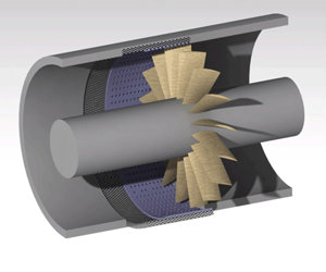
The physical model under consideration is shown in figure 1. Inside an infinite annular duct are a subsonic rotor spinning at angular speed  $\varOmega$ and a finite-length porous-material liner. The inner and outer duct radii are
  $R_h$ and
  $R_d$, respectively. Let
  $(x,r,\varphi )$ be the cylindrical coordinates fixed to the duct, with
  $\boldsymbol {n}_x$,
  $\boldsymbol {n}_r$ and
  $\boldsymbol {n}_\varphi$ being the corresponding unit vectors, and the circumferential coordinate
  $\varphi$ is prescribed to increase against the direction of rotor rotation (see figure 1a). The rotor is comprised of
  $B$ identical, equally spaced blades, whose axial chord length
  $C_a=x_R^{2}-x_R^{1}$ is assumed to be constant along the blade span. Here,
  $x_R^{1}$ and
  $x_R^{2}$ denote the axial coordinates of the blade leading and trailing edges, respectively. The duct walls are entirely hard except for the lined section of finite axial extent
  $L_a=x_L^{2}-x_L^{1}$ on the outer duct wall, where
  $x_L^{1}$ and
  $x_L^{2}$ are the axial coordinates of the upstream and downstream ends of the liner, respectively. The non-locally reacting liner is comprised of a cavity of radial depth
  $h_{cav}$, filled with the uniform porous material of flow resistivity
  $R_f$, and a facing screen of thickness
  $t_p$ and open area ratio
  $\zeta$, perforated with uniformly spaced circular holes of diameter
  $d_h$ (see figure 1b).

Figure 1. The physical model under investigation: (a) the duct system; (b) the porous-material liner.
It is known that when both flow compressibility and finite steady blade forces are strictly taken into account, the second-order terms of mean flow disturbance and the cross products of mean disturbance and unsteady disturbance become non-negligible as compared to the first-order terms of unsteady disturbance (Namba Reference Namba1975). To conduct a three-dimensional semi-analytical analysis within the linear scope, necessary simplifications are thus required. In the scope of linear acoustic theory, the mean loading effect is known to appear largely as a modification of the effective cascade geometry, which mainly affects the sound propagation through a blade row as well as the downstream radiation (Hall & Verdon Reference Hall and Verdon1991; Evers & Peake Reference Evers and Peake2002; Peake & Kerschen Reference Peake and Kerschen2004). The numerical simulations of Hall & Verdon (Reference Hall and Verdon1991) also showed that for low-speed flows, the effect of blade thickness on unsteady gust–cascade interaction might be quite limited. It is thus inferred that for the present problem, the effect of mean loading associated with blade geometry and small angle of attack may modify the ducted sound field to a certain degree, thereby leading to a quantitative change of the sound absorption by a given liner. However, since our primary concern is the noise attenuation mechanisms governed by the unsteady rotor–liner interaction, zero steady blade loading is assumed, whereas the unsteady blade loading distribution will be under fully three-dimensional consideration. Further, with fluid viscosity and thermal conductivity neglected, the ducted flow field is regarded as the superposition of small-amplitude isentropic perturbations and a uniform axial time-averaged flow of density  $\rho _0$, pressure
  $p_0$, speed of sound
  $c_0$, and Mach number
  $M_a$. The corresponding mean flow velocity relative to the duct and that relative to the rotor are
  $U=M_ac_0$ and
  $W=\sqrt {U^{2}+\varOmega ^{2}r^{2}}< c_0$, respectively. The rotor blades are then idealized as the zero-thickness twisted sheets of orientation parallel to the mean flow vector through the row.
Over the years, there have been lasting debates in the literature about whether particle displacement match or particle velocity match should be enforced on a lined wall. A popular belief at the present time is that as the ratio of the acoustic and stationary boundary layer thicknesses increases, the kinematic wall condition changes gradually from continuity of normal acoustic particle displacement to continuity of normal acoustic perturbation velocity (Aurégan, Starobinski & Pagneux Reference Aurégan, Starobinski and Pagneux2001; Jing et al. Reference Jing, Sun, Wu and Meng2001; Renou & Aurégan Reference Renou and Aurégan2011). In this fundamental study focusing on the rotor–liner interaction mechanisms, however, the former is enforced with the assumption of a vanishingly thin vortex sheet over the lined wall, separating the moving fluid within the duct and the fluid at rest in the liner cavity. In terms of acoustic properties, the uniform porous material filling the liner cavity can be modelled as an equivalent fluid, the damped sound propagation through which is characterized by the complex-valued fluid density  $\rho _e$ and sound speed
  $c_e$ (Scott Reference Scott1946). In view of the lack of acoustic data for foam–metals in the open literature, the empirical equivalent fluid model used by Selamet et al. (Reference Selamet, Xu, Lee and Huff2004) for a fibrous-material liner is employed in this work. The explicit expressions for the acoustic properties of the porous material as well as the specific impedance of the perforated plate
  $Z_p$ (scaled with respect to
  $\rho _0c_0$) are presented in Appendix A. In this simplified impedance model, no account is taken of the effects of grazing flow (Jing et al. Reference Jing, Sun, Wu and Meng2001) and high acoustic intensity (Jing & Sun Reference Jing and Sun2002) (in the proximity of a fan rotor) on the quantitative modifications of the perforated plate impedance.
Generally, there are two types of excitation disturbances of acoustic interest to the considered duct system: first, convected vorticities, e.g. wakes shed from upstream obstacles; and second, incident sound waves. In both cases, the perturbed duct field is generated as a result of the coupled unsteady responses of the rotor and the liner to the excitation. In order to capture effectively the flow-acoustic coupling therein, a simultaneous solution to the unsteady interaction field is constructed as follows.
3. Mathematical formulation
3.1. Perturbed duct field and boundary conditions
To circumvent the complexities of seeking and treating the eigensolutions for a partially lined flow duct, the Green's function  $G(\boldsymbol {x}^{\prime },\tau \mid \boldsymbol {x},t)$, whose normal derivative vanishes on the entire duct walls, is employed in the present method. This allows us to formulate the disturbances generated within the duct consistently as the series expansions in terms of the orthogonal hard-walled duct modes. Here,
  $\boldsymbol {x}$ and
  $\boldsymbol {x}^{\prime }$ are the vector coordinates of observation point and source point, respectively, and
  $t$ and
  $\tau$ denote time. Further, on the basis of linearization, we split the perturbed duct field into: (1) excitation disturbances with unsteady pressure
  $\tilde {p}_E$ and unsteady fluid velocity
  $\tilde {\boldsymbol {u}}_E$; (2) the rotor-scattering field with
  $\tilde {p}_R^{s}$ and
  $\tilde {\boldsymbol {u}}_R^{s}$; and (3) the liner-scattering field with
  $\tilde {p}_L^{s}$ and
  $\tilde {\boldsymbol {u}}_L^{s}$. In this paper, the tilde symbol denotes the quantities of harmonic time dependence
  $\mathrm {e}^{\mathrm {i} \omega t}$, where
  $\omega$ is the angular frequency of the disturbances in the duct-fixed frame of reference.
The rotor-scattering field is defined as the perturbed field excited by the pressure dipoles, corresponding to the actual unsteady aerodynamic forces  $-\Delta \tilde {p}^{q} \boldsymbol {n}_{\hat {\varphi }}$ exerted by the blades on the fluids, as if they were in the corresponding hard-walled duct. Here,
  $q \in [1, B]$ is the blade index increasing in the positive direction of the
  $\varphi$-axis, and
  $\boldsymbol {n}_{\hat {\varphi }}$ is the unit vector normal to the blade surface
  $S_q$ (see figure 2). Similarly, the liner-scattering field, with acoustic pressure
  $\tilde {p}_L^{s}$ in the main duct and
  $\tilde {p}_{cav}^{s}$ in the liner cavity (see figure 1b), accounts for the sound radiation from the equivalent mass sources (i.e. monopoles). The mass source strength is proportional to the non-zero normal particle velocity
  $\tilde {V}_{r}$ on the lined wall.

Figure 2. Blade force triangle and mean flow velocity triangle.
The flow tangency condition on the hard portion of the duct walls (i.e.  $\tilde {V}_{r}=0$) has been guaranteed naturally by our choice of the Green's function
  $G$. In addition, the resultant perturbed field must satisfy the impermeable boundary condition
 \begin{equation} \left[ \tilde{\boldsymbol{u}}_{E} + \tilde{\boldsymbol{u}}_{R}^{s} \left( \Delta \tilde{p}^{q} \right) + \tilde{\boldsymbol{u}}_{L}^{s}( \tilde{V}_{r} ) \right] \boldsymbol{\cdot} \boldsymbol{n}_{\hat{\varphi}}=0 \end{equation}
on the rotating blade surfaces  $S_q$ (for
  $q=1, \ldots, B$), where
  $x_R^{1} \leqslant x \leqslant x_R^{2}$,
  $R_h \leqslant r \leqslant R_d$ and
  $\varphi =\varOmega x/U+ 2 {\rm \pi}( q-1 ) /B-\varOmega t$, as well as the impedance boundary condition
 \begin{equation} \frac{\tilde{p}_E + \tilde{p}_{R}^{s} \left( \Delta \tilde{p}^{q} \right) + \tilde{p}_{L}^{s} ( \tilde{V}_{r} ) - \tilde{p}_{cav}^{s} ( \tilde{V}_{r} )}{\tilde{V}_{r}} = \rho_0 c_0\,Z_p \left( \omega \right) \end{equation}
on the liner surface  $S_L$, where
  $x_L^{1} \leqslant x \leqslant x_L^{2}$,
  $r=R_d$ and
  $0\leqslant \varphi \leqslant 2{\rm \pi}$. Note that the unit vector
  $\boldsymbol {n}_r$ normal to
  $S_L$ points outwards from the ducted region (see figure 1b). For any given excitation disturbances
  $\tilde {p}_E$ and
  $\tilde {\boldsymbol {u}}_E$, (3.1) and (3.2) are the coupled equations with respect to the underdetermined singularity distributions
  $\Delta \tilde {p}^{q}$ and
  $\tilde {V}_{r}$, which are generated respectively by the rotor and the liner in response to the external perturbations that they are subject to.
3.2. Modelling of the unsteady rotor response
The present rotor modelling is based mainly on the three-dimensional lifting surface theory developed by Namba (Reference Namba1977). As the derivation of the unsteady cascade response function based on this theory has been surveyed in a series of previous papers (Zhang, Wang & Sun Reference Zhang, Wang and Sun2015; Zhang et al. Reference Zhang, Wang, Jing, Liang and Sun2017, Reference Zhang, Wang, Du and Sun2019; Sun et al. Reference Sun, Wang, Du and Sun2020a,Reference Sun, Wang, Du and Sunb), the formulation is outlined briefly as follows.
Based on the generalized acoustic analogy (Goldstein Reference Goldstein1974), the rotor-scattering acoustic field is formulated as
 \begin{equation} \tilde{p}_{R}^{s}\left( \boldsymbol{x}, t \right) = -\int_{{-}T}^{T} \left[ \sum_{q=1}^{B} \int_{S_q\left(\boldsymbol{x}^{\prime}\right)} \Delta \tilde{p}_{j}^{q} ( \boldsymbol{x}^{\prime}, \tau )\,\frac{\partial G}{\partial x^{\prime}_{j}} \,{\rm d}S_{q} (\boldsymbol{x}^{\prime}) \right]_{\boldsymbol{x}^{\prime}=\boldsymbol{x}^{\prime}\left(\tau\right)}{\rm d}\tau, \end{equation}
where  $T$ denotes a large but finite time interval. Excited by the oncoming perturbations of interblade phase angle (IBPA)
  $\sigma$ and harmonic time dependence
  $\mathrm {e}^{\mathrm {i} \lambda t}$ in the rotor-fixed coordinates
  $(x,r,\bar {\varphi }=\varphi +\varOmega t)$, the unsteady blade loading has the form
 \begin{equation} \Delta \tilde{p}^{q} ( \boldsymbol{x}^{\prime}, \tau ) = \Delta p ( x^{\prime}, r^{\prime} ) \mathrm{e}^{\mathrm{i} ( q - 1 ) \sigma}\, \mathrm{e}^{\mathrm{i} \lambda \tau}, \end{equation}
where  $\Delta p ( x^{\prime }, r^{\prime } )\,\mathrm {e}^{\mathrm {i} \lambda \tau }$ represents the unsteady pressure jump across the reference blade
  $S_R$ (i.e.
  $S_{q=1}$ where
  $\bar {\varphi } = \varOmega x/U$). Substituting (3.4) and the expression for the Green's function
  $G$ (see (3) in Zhang et al. (Reference Zhang, Wang and Sun2015), or equivalently (10) in Sun et al. (Reference Sun, Wang, Du and Jing2008)) into (3.3) leads to
 \begin{equation} \tilde{p}_{R}^{s} \left( \boldsymbol{x}, t \right) = \int_{R_{h}}^{R_{d}} \int_{x_{R}^{1}}^{x_{R}^{2}} \Delta p ( x^{\prime}, r^{\prime} )\,K_{R}^{p} ( x^{\prime}, r^{\prime} \mid x, r, \varphi, t )\,{{\rm d}\kern0.7pt x}^{\prime}\, {\rm d}r^{\prime}. \end{equation}
Correspondingly, the induced upwash velocity, i.e.  $\tilde {\boldsymbol {u}}_{R}^{s} \boldsymbol {\cdot } \boldsymbol {n}_{\hat {\varphi }}$ on
  $S_R$, can be written as
 \begin{equation} \tilde{u}_{R,\hat{\varphi}}^{s} = \mathrm{e}^{\mathrm{i} \lambda t} \int_{R_{h}}^{R_{d}} \int_{x_{R}^{1}}^{x_{R}^{2}} \Delta p ( x^{\prime}, r^{\prime} )\,K_{R}^{u} ( x^{\prime}, r^{\prime} \mid x, r )\,{{\rm d}\kern0.7pt x}^{\prime} \,{\rm d}r^{\prime}. \end{equation}
The kernel functions in (3.5) and (3.6) are of the forms
 \begin{align} & K_{R}^{p} ( x^{\prime}, r^{\prime} \mid x, r, \varphi, t ) \nonumber\\ &\quad = \frac{B}{4{\rm \pi}} \sum_{h^{s}={-}\infty}^{\infty} \exp({\mathrm{i} \omega t}) \exp({\mathrm{i}m \varphi} )\exp({- \mathrm{i} ({m \varOmega x^{\prime}}/{U}) }) \sum_{n=0}^{\infty} \frac{1}{\kappa_{n,m}}\,\phi_{m} ( k_{mn} r )\,\phi_{m} ( k_{mn} r^{\prime} ) \nonumber\\ & \qquad \times \left[ H ( x^{\prime} - x ) \left( \frac{m}{r^{\prime}} - \gamma_{mn}^{+}\,\dfrac{\varOmega r^{\prime}}{U} \right) \exp\left(\mathrm{i}\gamma_{mn}^{+} ( x - x^ {\prime} )\right)\right.\nonumber\\ & \qquad \left. + H ( x - x^{\prime} ) \left( \frac{m}{r^{\prime}} - \gamma_{mn}^{-}\,\frac{\varOmega r^{\prime}}{U} \right) \exp\left({\mathrm{i} \gamma_{mn}^{-}( x-x^ {\prime})} \right) \right] \end{align}
and
 \begin{align} K_{R}^{u} ( x^{\prime}, r^{\prime} \mid x, r)&= \frac{B}{2{\rm \pi} \rho_{0} W} \sum_{h^{s}={-}\infty}^{\infty} \sum_{n=0}^{\infty} \phi_{m} ( k_{mn} r )\, \phi_{m} ( k_{mn} r^{\prime} ) \nonumber\\ &\quad \times \left[ - H ( x^{\prime} - x ) \frac{M_{a} ( 1 - M_{a}^{2} ) \exp\left({\mathrm{i} \left( \gamma_{mn}^{+} + m\,\dfrac{\varOmega}{U} \right) ( x - x^ {\prime} ) }\right)}{2 \kappa_{n,m} ( M_{a} \kappa_{n,m} + k_{0} )} \right.\nonumber\\ &\quad \times \left( \frac{m}{r} - \gamma_{mn}^{+}\,\frac{\varOmega r}{U} \right) \left( \frac{m}{r^{\prime}} - \gamma_{mn}^{+}\,\frac{\varOmega r^{\prime}}{U} \right) + H ( x - x^{\prime} ) \nonumber\\ &\quad \times \frac{M_{a} ( 1 - M_{a}^{2} ) \exp\left({\mathrm{i} \left( \gamma_{mn}^{-} + m\,\dfrac{\varOmega}{U} \right) ( x - x^ {\prime} ) }\right)}{2 \kappa_{n,m} ( M_{a} \kappa_{n,m} - k_{0} )}\nonumber\\ &\quad \times \left( \frac{m}{r} - \gamma_{mn}^{-}\,\dfrac{\varOmega r}{U} \right) \left( \dfrac{m}{r^{\prime}} - \gamma_{mn}^{-}\,\dfrac{\varOmega r^{\prime}}{U} \right) + H ( x - x^{\prime} )\nonumber\\ &\quad \times \dfrac{M_{a}^{2} \exp\left({\mathrm{i} \left( \gamma_{v} + m\,\dfrac{\varOmega}{U} \right) ( x - x^ {\prime} ) }\right)}{k_{0}^{2} + M_{a}^{2} k_{mn}^{2}}\nonumber\\ &\quad \times\left. \left( \dfrac{m}{r} - \gamma_{v}\,\dfrac{\varOmega r}{U} \right) \left( \dfrac{m}{r^{\prime}} - \gamma_{v}\,\dfrac{\varOmega r^{\prime}}{U} \right) \right], \end{align}
where  $H(x)$ is the Heaviside function, and
  $k_0 \equiv \omega /c_0$. Here,
  $k_{mn}$ and
  $\phi _{m}(k_{mn} r)$ denote respectively the eigenvalue and the normalized eigenfunction of circumferential mode number
  $m$ and radial node order
  $n$ for the annular hard-walled duct. The expressions for
  $\kappa _{n,m}$, the axial wavenumbers of the acoustic waves
  $\gamma _{mn}^{\pm }$ (with the upstream- and downstream-propagating modes distinguished respectively by the superscripts
  $+$ and
  $-$) and those of the vortical waves
  $\gamma _{v}$, are given in Appendix B. The scattering disturbances excited at the tuned rotor are of the mode and frequency contents
 \begin{equation} \begin{array}{cc} m = m^{i} + h^{s}B, \\ \omega = \lambda + m \varOmega = \omega^{i} + h^{s} B \varOmega \end{array} \quad (h^{s} = 0, \pm 1, \pm 2, \ldots), \end{equation}
where the integer  $h^{s}$ denotes the harmonic number corresponding to a scattering mode. Here,
  $m^{i}$ and
  $\omega ^{i} = \lambda + m^{i} \varOmega$ indicate, respectively, the circumferential periodicity and the angular frequency of the external perturbation viewed in the duct-fixed frame of reference.
It is required that the induced upwash velocity  $\tilde {u}_{R,\hat {\varphi }}^{s}$ cancel the upwash component of the external perturbation velocity
  $\tilde {u}_{R,\hat {\varphi }}^{i} = u_{R,\hat {\varphi }}^{i} (x,r,\bar {\varphi })\, \mathrm {e}^{\mathrm {i} \lambda t}$ on each blade surface. Due to the time and spatial periodicity, the events on all the blades are identical except for a constant IBPA
  $\sigma$. The impermeable boundary condition on the
  $B$ rotating blade surfaces thus reduces to a single integral equation:
 \begin{equation} \int_{R_{h}}^{R_{d}} \int_{x_{R}^{1}}^{x_{R}^{2}} \Delta p ( x^{\prime}, r^{\prime} )\,K_{R}^{u} ( x^{\prime}, r^{\prime} \mid x, r )\,{{\rm d}\kern0.7pt x}^{\prime} \,{\rm d}r^{\prime} ={-} u_{R,\hat{\varphi}}^{i}(x,r,\bar{\varphi}), \end{equation}
for  $x_R^{1} \leqslant x \leqslant x_R^{2}$,
  $R_h \leqslant r \leqslant R_d$ and
  $\bar {\varphi } = \varOmega x/U$. In principle, there are many strategies to solve the unsteady blade loading distribution
  $\Delta p ( x^{\prime }, r^{\prime } )$ from (3.10). Nevertheless, in order to obtain a physically meaningful solution of
  $\Delta p$ that satisfies the Kutta condition at the trailing edge, we solve (3.10) on the basis of Glauert's solution to the thin aerofoil problem (Glauert Reference Glauert1926). Furthermore, the finite radial mode expansion proposed by Namba (Reference Namba1977) is employed to address properly the convergence problem arising from the series superposition in (3.8). As a result,
  $\Delta p$ is cast into the form
 \begin{equation} \Delta p ( x^{\prime}, r^{\prime} ) = \sum_{j^{\prime}=0}^{N_{r} - 1} \phi_{0} ( k_{0 j^{\prime} } r^{\prime} ) \left[ F_{1 j^{\prime}} \cot \frac{\vartheta^{\prime}}{2} + \sum_{i^{\prime}=2}^{N_{x}} F_{i^{\prime} j^{\prime}} \sin ( i^{\prime} - 1 ) \vartheta^{\prime} \right], \end{equation}
with the coordinate transformation
 \begin{equation} x^{\prime} = x_{R}^{1} + \frac{C_{a}}{2}\,( 1 - \cos \vartheta^{\prime} ) \quad ( \mbox{for } 0 \leqslant \vartheta^{\prime} \leqslant {\rm \pi}). \end{equation}
Note that we have truncated the double series in (3.11) for numerical computation. Accordingly, the higher-order duct eigenfunctions  $\phi _{m} ( k_{mn} r )$ in (3.8) are approximated by the finite series expansions in terms of the eigenfunctions
  $\phi _{0} ( k_{0j} r )$ of
  $m=0$:
 \begin{equation} \left.\begin{gathered} \phi_{m} ( k_{mn} r ) = \sum_{j=0}^{N_{r} - 1} B_{n,j}^{m}\,\phi_{0} ( k_{0j} r ), \\ \frac{\phi_{m} ( k_{mn} r )}{r^{2}} = \sum_{j=0}^{N_{r} - 1} C_{n,j}^{m}\,\phi_{0} ( k_{0j} r ), \end{gathered}\right\} \end{equation}
where  $B_{n,j}^{m}$ and
  $C_{n,j}^{m}$ are the constants derived from the Bessel equations (see Namba Reference Namba1977). Substituting (3.13) into (3.8) with the corresponding singularity treatments gives the kernel function of uniform convergence. Finally, with the resultant expression for
  $K_{R}^{u}$ along with (3.11) inserted, (3.10) is enforced at a set of collocation points on the blade surface
  $S_R$:
 \begin{equation} \left(\vartheta_{i^{\prime\prime}}=\frac{(2i^{\prime\prime}-1)}{2N_x}\,{\rm \pi}, r_{j^{\prime\prime}}=R_{h} + \frac{(2j^{\prime\prime}-1)}{2N_r}\,(R_d-R_h) \right), \end{equation}
for  $i^{\prime \prime } = 1, \ldots, N_x$ and
  $j^{\prime \prime } = 1, \ldots,N_r$. This leads to a matrix equation for the underdetermined blade force coefficients
  $F_{i^{\prime } j^{\prime }}$:
 \begin{equation} \left[ K^{F}_{i^{\prime\prime} j^{\prime\prime},i^{\prime} j^{\prime}} \right] _{N_{x}N_{r} \times N_{x} N_{r}} \left[ F_{i^{\prime} j^{\prime}} \right]_{N_{x} N_{r} \times 1} = \left[ U^{i}_{i^{\prime\prime} j^{\prime\prime}} \right]_{N_{x} N_{r} \times 1}, \end{equation}
where  $U^{i}_{i^{\prime \prime } j^{\prime \prime }} = u^{i}_{R,\hat {\varphi }} ( x = x ( \vartheta _{i^{\prime \prime }} ), r = r_{j^{\prime \prime }}, \bar {\varphi }=\varOmega x/U )$. The orthogonality of the hard-walled duct eigenfunctions, i.e.
  $\int _{R_{h}}^{R_d} \phi _{0} ( k_{0j} )\,\phi _{0} ( k_{0 j^{\prime }} )\,r\,\textrm {d}r = \delta _{j^{\prime } j}$ (where
  $\delta _{j^{\prime } j}$ is the Kronecker delta), can accelerate considerably the convergence of the elements in the kernel matrix
  $[ K^{F}_{i^{\prime \prime } j^{\prime \prime },i^{\prime } j^{\prime }} ]$. It should be emphasized that (3.15) governs the unsteady rotor response to all the excitation disturbances of the same angular frequency
  $\lambda$ and the same IBPA
  $\sigma$ in the rotor-fixed frame of reference.
3.3. Modelling of the unsteady liner response
Allowing sound propagation within the unpartitioned cavity in any direction, the liner in question is non-locally reacting to the incident sound. Hence, unlike the locally reacting liners with perforate-over-honeycomb structures, its acoustic effect cannot be simply characterized by a surface impedance model for the whole liner. Rather, only through a simultaneous solution of the liner-scattering field within the main duct  $\tilde {p}_{L}^{s}$ and that inside the cavity
  $\tilde {p}_{cav}^{s}$ can one determine the liner response to a given incident sound field
  $\tilde {p}_{L}^{i}$.
As stated earlier, in the present model, the viscous boundary layer over the lining is neglected, and continuity of normal particle displacement is enforced as the lined wall boundary condition. The liner-scattering field is then solved as the sum of the hard-walled duct modes by employing the equivalent surface source method (Namba & Fukushige Reference Namba and Fukushige1980; Sun et al. Reference Sun, Wang, Du and Jing2008). This allows us to avoid the possible difficulty in choosing the direction of propagation of soft-walled duct modes, identified by Brambley (Reference Brambley2009) as the ill-posed problem of simple vortex sheet models in frequency-domain analyses. Nevertheless, when an improved characterization of the liner response is required, it seems possible to consider the effect of a thin viscous boundary layer over the lining in our model by taking an appropriately modified lined wall impedance, as suggested by Aurégan et al. (Reference Aurégan, Starobinski and Pagneux2001) and also Renou & Aurégan (Reference Renou and Aurégan2011).
Excited by the incident sound field  $\tilde {p}_{L}^{i} = p_{L}^{i} (x,r) \exp ({\mathrm {i} m^{i} \varphi })\exp ({\mathrm {i} \omega ^{i} t})$, the acoustic particle displacement
  $\tilde {\boldsymbol {\eta }}$ on the partially lined casing wall has the normal component
 \begin{equation} \tilde{\eta}_{r} ( x, r=R_{d}, \varphi, t ) = \left\{ \begin{array}{ll} \eta_{r} ( x ) \exp({\mathrm{i} m^{i} \varphi})\exp({\mathrm{i} \omega^{i} t}), & \mbox{for } x_{L}^{1} \leqslant x \leqslant x_{L}^{2}, \\[3pt] 0, & \mbox{otherwise}. \end{array} \right. \end{equation}
The normal particle velocity through the perforated plate  $S_L$ can then be expressed as
 \begin{equation} \tilde{V}_{r}(\boldsymbol{x}, t) = \frac{{\partial {{\tilde \eta }_r}}}{{\partial t}} = \mathrm{i} {\omega ^{i}}\,{\eta _r}(x) \exp({\mathrm{i} {m^{i}} \varphi})\exp({{\mathrm i} {\omega ^{i}} t}). \end{equation}
Further, the normal component of the acoustic perturbation velocity just below the perforated plate (towards the ducted mean flow) is defined by
 \begin{equation} \tilde{V}_{r}^{\prime}(\boldsymbol{x}, t) = \frac{{\mathrm{D} {{\tilde{\eta}}_r}}}{{\mathrm{D} t}} = \left( 1 + \frac{U}{\mathrm{i} \omega^{i}}\, \frac{\partial}{\partial x}\right) \tilde{V}_{r}, \end{equation}
where  $\mathrm {D}/\mathrm {D} t \equiv \partial / \partial t + U\,\partial / \partial x$. Based on the generalized acoustic analogy (Goldstein Reference Goldstein1974), the liner-scattering fields are formulated as
 $$\begin{gather} \tilde{p}_L^{s}({\boldsymbol{x}},t) = \int_{{-}T}^{T} {\int_{S_L} {{\rho _0}\,{{\tilde V}_r}^{\prime} ({\boldsymbol{x}^{\prime}},\tau )\,\frac{{{\rm{D}}G}}{{{\rm{D}}\tau }}\,{\rm d}{S_L}({\boldsymbol{x}^{\prime}})} } \,{\rm d}\tau , \end{gather}$$
 $$\begin{gather}\tilde{p}_{cav}^{s}({\boldsymbol{x}},t) ={-} \int_{{-}T}^{T} {\int_{S_L} {{\rho _0}\,{{\tilde V}_r} ({\boldsymbol{x}^{\prime}},\tau )\,\frac{\partial G_{cav}}{\partial \tau }\,{\rm d}{S_L}({\boldsymbol{x}^{\prime}})} } \,{\rm d}\tau , \end{gather}$$
where
 \begin{equation} \left.\begin{gathered} \tilde{V}_{r}(\boldsymbol{x}^{\prime},\tau) = V_r (x^{\prime}) \exp({\mathrm{i} m^{i} \varphi^{\prime}})\exp({\mathrm{i} \omega^{i} \tau}),\\ \tilde{V}_{r}^{\prime}(\boldsymbol{x}^{\prime},\tau) = \left(1+\frac{U}{\mathrm{i} \omega^{i} }\,\frac{\partial}{\partial x^{\prime}}\right) V_r (x^{\prime}) \exp({\mathrm{i} m^{i} \varphi^{\prime}}) \exp({\mathrm{i} \omega^{i} \tau}) \end{gathered}\right\} \end{equation}
represent the mass source densities on the lined section. Here,  $G_{cav}$ is the Green's function for the annular cavity containing the stationary equivalent fluid of the porous material, subject to the hard-wall boundary conditions. It is in the form of (38) in Sun et al. (Reference Sun, Wang, Du and Jing2008), with
  $\rho _0$ and
  $c_0$ replaced by the complex-valued equivalent fluid density
  $\rho _e$ and sound speed
  $c_e$, respectively. The sound scatterings on a uniform lined wall occur only among different radial modes, such that the liner-scattering fields are of the same time dependence and circumferential mode number with the incident acoustic field, i.e.
  $\tilde {p}_L^{s} = p_L^{s} (x,r)\,\mathrm {e}^{\mathrm {i} m^{i} \varphi }\, \mathrm {e}^{\mathrm {i} \omega ^{i} t}$ and
  $\tilde {p}_{cav}^{s} = p_{cav}^{s} (x,r)\,\mathrm {e}^{\mathrm {i} m^{i} \varphi }\,\mathrm {e}^{\mathrm {i} \omega ^{i} t}$. The impedance boundary condition thus gives
 \begin{equation} \frac{p_{L}^{i}(x,R_d) + p_{L}^{s}(x,R_d) - p_{cav}^{s}(x,R_d)}{V_{r}(x)} = \rho _{0} c_{0}\,Z_{p} (\omega^{i}) \quad (\mbox{for } x_{L}^{1} \leqslant x \leqslant x_{L}^{2}). \end{equation}
As both  $p_L^{s}$ and
  $p_{cav}^{s}$ are expressed as integrals with respect to the normal particle velocity distribution on the lined section, (3.22) is essentially an integral equation for
  $V_{r}(x^{\prime })$. Various singularity problems hinder a straightforward solution to (3.22) (Namba & Fukushige Reference Namba and Fukushige1980). Therefore, similar to the solving approach of the unsteady blade loading distribution,
  $V_{r}(x)$ is expanded into
 \begin{equation} {V_r}(x) = \sum_{l = 1}^{\infty} {{V_l}\sin \frac{{l{\rm \pi} (x - x_L^{1})}}{{{L_a}}}} \quad (\mbox{for } x_{L}^{1} \leqslant x \leqslant x_{L}^{2}), \end{equation}
where
 \begin{equation} {V_l} = \frac{2}{{{L_a}}}\int_{x_L^{1}}^{x_L^{2}} {\sin \frac{{l{\rm \pi} (x - x_L^{1})}}{{{L_a}}}\,{V_r}(x)\,{{\rm d}\kern0.7pt x}}. \end{equation}
Then we apply the inverse sine transform as follows:
 \begin{equation} \begin{array}{l} {\dfrac{2}{{{L_a}}}\displaystyle\int_{x_L^{1}}^{x_L^{2}} {\sin \dfrac{{l'{\rm \pi} (x - x_L^{1})}}{{{L_a}}}\,p_L^{s}(x,r = {R_d})\,{{\rm d}\kern0.7pt x}} = \displaystyle\sum_{l = 1}^{\infty} {Z_{l'l}^{duct}{V_l}} } \\ {\dfrac{2}{{{L_a}}}\displaystyle\int_{x_L^{1}}^{x_L^{2}} {\sin \dfrac{{l'{\rm \pi} (x - x_L^{1})}}{{{L_a}}}\,p_{cav}^{s}(x,r = {R_d})\,{{\rm d}\kern0.7pt x}} = \displaystyle\sum_{l = 1}^{\infty} {Z_{l'l}^{cav}{V_l}} } \\ {\dfrac{2}{{{L_a}}}\displaystyle\int_{x_L^{1}}^{x_L^{2}} {\sin \dfrac{{l'{\rm \pi} (x - x_L^{1})}}{{{L_a}}}\,p_L^{i}(x,r = {R_d})\,{{\rm d}\kern0.7pt x}} = P_{l'}^{i}} \end{array} \quad (\mbox{for } l^{\prime} = 1, 2, \ldots ). \end{equation}
The explicit expressions for  $Z_{l^{\prime } l}^{duct}$ and
  $Z_{l^{\prime } l}^{cav}$ can be found in Sun et al. (Reference Sun, Wang, Du and Jing2008) (see (20) therein for
  $Z_{l^{\prime } l}^{duct}$, and (47) for
  $Z_{l^{\prime } l}^{cav}$, noting that a negative sign should be added due to the contrary positive direction of the unit surface normal prescribed here). Truncating the infinite sine series with the first
  $N_l$ terms retained, we arrive at a set of simultaneous algebraic equations for the unknown particle velocity coefficients
  $V_l$, which can be written in the matrix form
 \begin{equation} {\left[ {K_{l',l}^{V}} \right]_{{N_l} \times {N_l}}} \cdot {\left[ {{V_l}} \right]_{{N_l} \times 1}} = {\left[ {P_{l'}^{i}} \right]_{{N_l} \times 1}}, \end{equation}
with the kernel matrix defined by
 \begin{equation} K_{l',l}^{V} ={-} (Z_{l'l}^{duct} - Z_{l'l}^{cav} - {\rho _0}{c_0}{Z_p}{\delta _{l'l}}). \end{equation}
Note that (3.26) is restricted to the unsteady liner response to the incident sound field  $\tilde {p}_{L}^{i}$ of a single angular frequency
  $\omega ^{i}$ and a single circumferential mode number
  $m^{i}$ (with the superimposed contributions from different radial modes
  $n^{i}$). For a more complex incident field, the orthogonality of harmonic time factors and that of hard-walled duct eigenfunctions allow us to compute the resultant scattering fields
  $\tilde {p}_{L}^{s}$ and
  $\tilde {p}_{cav}^{s}$ as the simple sum of the mode-to-mode liner responses.
3.4. Formulation of the acoustic coupling problem
So far, we have established the unsteady response equations, respectively, for the annular rotor and the porous-material liner. Their interaction problem governed by (3.1) and (3.2) can now be formulated into a set of coupled algebraic equations for the singularity expansion coefficients by rewriting the incident perturbation terms on the right-hand sides of (3.15) and (3.26).
Without loss of generality, we consider that the excitation disturbances in the duct system have the normal fluctuating velocity component
 \begin{equation} {\tilde{u}_{E,\hat{\varphi}}} = {u_{E,\hat{\varphi}}}(x,r)\exp({{\rm i}(q - 1)\sigma }) \exp({{\rm i}\lambda t}) \quad \left(\mbox{for }x_R^{1} \leqslant x \leqslant x_R^{1}, {R_h} \leqslant r \leqslant {R_d}, \bar \varphi = \frac{{\varOmega x}}{U}\right) \end{equation}
on the rotor blade surfaces  $S_q$, and on the liner surface
  $S_L$ have the unsteady pressure
 \begin{equation} {\tilde{p}_{E}} = \sum_{{h^{i}}} p_E^{{h^{i}}}(x,r)\exp({{\rm i}{\omega ^{i}}t})\exp({{\rm i}{m^{i}}\varphi }) \quad (\mbox{for }x_R^{1} \leqslant x \leqslant x_R^{1}, r={R_d}, 0 \leqslant \varphi \leqslant 2{\rm \pi}). \end{equation}
The mode and frequency characteristics of the excitation disturbances are described by
 \begin{equation} \left.\begin{gathered} {{m^{i}} = \mu + {h^{i}}B}, \\ {{\omega ^{i}} = \lambda + {m^{i}}\varOmega }, \end{gathered}\right\} \end{equation}
where the integer  $h^{i}$ is the harmonic number, and the interblade phase parameter is
  $\mu =\sigma B/2{\rm \pi} \in (0, B]$. Subject to the sound scatterings at the rotor (governed by (3.9a,b)) and the liner (only among different radial modes), the unsteady interaction field generated within the duct is comprised of the infinite mode and frequency components
 \begin{equation} \begin{array}{c} m = \mu + hB, \\ \omega = \lambda + \mu \varOmega + h B \varOmega \end{array} \quad (h = h^{i} + h^{s} = 0, \pm 1, \pm 2, \ldots). \end{equation}
Nevertheless, it is known that the ducted sound field is dominated largely by the lower-order acoustic modes, as the higher-order modes contain only a limited portion of acoustic energy and propagate with rapidly damped amplitudes. This allows us to consider only the contributions from the modes of the  $N_m$ lowest circumferential mode numbers and the
  $N_n$ least radial node orders to the unsteady rotor–liner interaction. Then we can rewrite (3.15) as
 \begin{equation} {\left[ {K_{i^{\prime\prime}j^{\prime\prime},i^{\prime}j^{\prime}}^{F}} \right]_{{N_x}{N_r} \times {N_x}{N_r}}} \cdot {\left[ {{F_{i^{\prime}j^{\prime}}}} \right]_{{N_x}{N_r} \times 1}} = {\left[ {U_{i^{\prime\prime}j^{\prime\prime}}^{E} + U_{i^{\prime\prime}j^{\prime\prime}}^{L}} \right]_{{N_x}{N_r} \times 1}}. \end{equation}
On the right-hand side of (3.32) are the upwash velocities at the collocation points  $(x(\vartheta _{i^{\prime \prime }}),r_{j^{\prime \prime }})$ corresponding to the excitation disturbances
  ${\tilde {\boldsymbol {u}}}_E$ and the liner-scattering disturbances
  ${\tilde {\boldsymbol {u}}}_L^{s}({\tilde {V}}_r)$ in (3.1), respectively. One can determine the latter, i.e.
  $U_{i^{\prime \prime }j^{\prime \prime }}^{L}=u_{L,\hat {\varphi }}^{s}(x(\vartheta _{i^{\prime \prime }}),r_{j^{\prime \prime }})$, from (3.19) by resorting to the momentum equation in the upwash direction. Further, with (3.23) and (3.24) employed, we arrive at
 \begin{equation} {\left[ {U_{i^{\prime\prime}j^{\prime\prime}}^{L}} \right]_{{N_x}{N_r} \times 1}} = {\left[ {U_{i^{\prime\prime}j^{\prime\prime},hl}^{V}} \right]_{{N_x}{N_r} \times {N_m}{N_l}}}{\left[ {{V_{hl}}} \right]_{{N_m}{N_l} \times 1}}, \end{equation}
where  $V_{hl}$ is the
  $l^{\mathrm {th}}$ sine expansion coefficient of the normal particle velocity resulting from the acoustic waves of harmonic number
  $h$ (see (3.31)) incident on the liner surface, and the coefficients
  $U_{i^{\prime \prime }j^{\prime \prime },hl}^{V}$ are obtained as constants. In a similar fashion, (3.26) is rewritten as
 \begin{equation} {\left[ {K_{h^{\prime}l^{\prime},hl}^{V}} \right]_{{N_m}{N_l} \times {N_m}{N_l}}} {\left[ {{V_{hl}}} \right]_{{N_m}{N_l} \times 1}} = {\left[ {P_{h^{\prime}l^{\prime}}^{E} + P_{h^{\prime}l^{\prime}}^{R}} \right]_{{N_m}{N_l} \times 1}}, \end{equation}
where  $K_{h^{\prime } l^{\prime },hl}^{V} \equiv 0$ for
  $h^{\prime } \neq h$. The block diagonal matrix
  $[K_{h^{\prime } l^{\prime },hl}^{V}]_{N_m N_l\times N_m N_l}$ is comprised of the
  $N_m$ liner kernel matrices
  $[K_{l^{\prime },l}^{V}]_{N_l\times N_l}$ (see (3.27)) constructed respectively for the incident sound fields of the
  $N_m$ harmonic numbers
  $h^{\prime }$. According to (3.25),
 \begin{equation} \left.\begin{gathered} P_{h^{\prime} l^{\prime}}^{E}=\frac{2}{L_a}\int_{x_L^{1}}^{x_L^{2}}\sin{\frac{l^{\prime}{\rm \pi}(x-x_L^{1})}{L}}\,p_E^{h^{\prime}}(x,{r=R}_d)\,{{\rm d}\kern0.7pt x},\\ P_{h^{\prime} l^{\prime}}^{R}=\frac{2}{L_a}\int_{x_L^{1}}^{x_L^{2}}\sin{\frac{l^{\prime}{\rm \pi}(x-x_L^{1})}{L}}\,p_R^{s,h^{\prime}}(x,{r=R}_d)\,{{\rm d}\kern0.7pt x}. \end{gathered}\right\} \end{equation}
Further employing (3.5), (3.7) and (3.11), we have
 \begin{equation} {\left[ {P_{h^{\prime}l^{\prime}}^{R}} \right]_{{N_m}{N_l} \times 1}} = {\left[ {P_{h^{\prime}l^{\prime},i^{\prime}j^{\prime}}^{F}} \right]_{{N_m}{N_l} \times {N_x}{N_r}}} {\left[ {{F_{i^{\prime}j^{\prime}}}} \right]_{{N_x}{N_r} \times 1}}, \end{equation}
where the coefficients  $P_{h^{\prime } l^{\prime },i^{\prime } j^{\prime }}^{F}$ are obtained as constants.
Finally, substituting (3.33) into (3.32) and also (3.36) into (3.34) yields
 \begin{equation} \left.\begin{array}{cc} {{{\left[ {K_{i^{\prime\prime}j^{\prime\prime},i^{\prime}j^{\prime}}^{F}} \right]}_{{N_x}{N_r} \times {N_x}{N_r}}}{{\left[ {{F_{i^{\prime}j^{\prime}}}} \right]}_{{N_x}{N_r} \times 1}} = {{\left[ {U_{i^{\prime\prime}j^{\prime\prime}}^{E}} \right]}_{{N_x}{N_r} \times 1}} + {{\left[ {U_{i^{\prime\prime}j^{\prime\prime},hl}^{V}} \right]}_{{N_x}{N_r} \times {N_m}{N_l}}}{{\left[ {{V_{hl}}} \right]}_{{N_m}{N_l} \times 1}}}, \\ {{{\left[ {K_{h^{\prime}l^{\prime},hl}^{V}} \right]}_{{N_m}{N_l} \times {N_m}{N_l}}}{{\left[ {{V_{hl}}} \right]}_{{N_m}{N_l} \times 1}} = {{\left[ {P_{h^{\prime}l^{\prime}}^{E}} \right]}_{{N_m}{N_l} \times 1}} + {{\left[ {P_{h^{\prime}l^{\prime},i^{\prime}j^{\prime}}^{F}} \right]}_{{N_m}{N_l} \times {N_x}{N_r}}}{{\left[ {{F_{i^{\prime}j^{\prime}}}} \right]}_{{N_x}{N_r} \times 1}}}, \end{array} \right\} \end{equation}
from which one can determine simultaneously the singularity expansion coefficients  $F_{i^{\prime } j^{\prime }}$ and
  $V_{hl}$, in other words, the coupled unsteady responses of the rotor and the liner.
3.5. Excitation source and sound radiation
As mentioned earlier, there are two types of excitation disturbances of acoustic interest. If the excitation disturbances are the incident sound waves,  $p_E^{h^{i}}$ in (3.29) has the modal description
 \begin{align} p_{E}^{h^{i}} & = \sum_{n^{i}} \phi_{m^{i}}( k_{m^{i} n^{i}} r ) \nonumber\\ &\quad \times \left[ H (x_{E}^{+}-x)\,P_{m^{i}n^{i}}^{i+}(x_{E}^{+}) \exp\left({\mathrm{i} \gamma_{m^{i}n^{i}}^{+} (x-x_{E}^{+})}\right)\right. \nonumber\\ &\quad\left. + H(x-x_{E}^{-})\, P_{m^{i}n^{i}}^{i-}(x_{E}^{-}) \exp\left({\mathrm{i} \gamma_{m^{i}n^{i}}^{-} (x-x_{E}^{-})}\right) \right], \end{align}
where  $P_{m^{i}n^{i}}^{i\pm }$ denote the mode amplitudes of the incident sound waves emitted at the axial positions
  $x_E^{\pm }$. Again,
  $+$ and
  $-$ indicate upstream and downstream propagation, respectively. Then
  $u_{E,\hat {\varphi }}$ in (3.28) can be determined by resorting to the momentum equation. If the excitation disturbances are the convected vorticities, then
  $u_{E,\hat {\varphi }}$ represents the upwash component of the vortical velocity on the reference blade surface while
  $\tilde {p}_E\equiv 0$.
For a given excitation, the blade force coefficients  $F_{i^{\prime } j^{\prime }}$ and the particle velocity coefficients
  $V_{hl}$ are solved from (3.37). Once the sound scatterings at the rotor and the liner are determined, we can subsequently compute the interaction sound field
  $\tilde {p}(\boldsymbol {x},t)=\tilde {p}_{E}(\boldsymbol {x},t)+\tilde {p}_{R}^{s}(\boldsymbol {x},t)+\tilde {p}_{L}^{s}(\boldsymbol {x},t)$ as the sum of the orthogonal hard-walled duct modes:
 \begin{align} \tilde{p}({\boldsymbol{x}},t) = \sum_h \exp({\mathrm{i} \omega t})\exp({\mathrm{i} m \varphi}) \sum_n {\phi _m}({k_{mn}}r)P_{mn}(x), \end{align}
Let  $x_0^{u}$ and
  $x_0^{d}$ be the axial coordinates of the far upstream and far downstream observation points, respectively. The acoustic powers crossing the duct cross-section (Morfey Reference Morfey1971), transmitted upstream and downstream from the rotor–liner combination, can then be expressed as
 \begin{equation} \left.\begin{gathered} {{{\bar{E}}_u} = \sum_h {\sum_n {\frac{{{\rm \pi} {{\left| {P_{mn} (x_0^u)} \right|}^{2}}}}{{{\rho _0}{c_0}}}\, \frac{{{{( {1 - M_a^{2}} )}^{2}}{k_0}{\kappa _{n,m}}}}{{({k_0} + {M_a}{\kappa _{n,m}})^{2}}}} } } ,\\ {{{\bar{E} }_d} = \sum_h {\sum_n {\frac{{{\rm \pi} {{\left| {P_{mn} (x_0^d)} \right|}^{2}}}}{{{\rho _0}{c_0}}}\,\frac{{{{( {1 - M_a^{2}} )}^{2}}{k_0}{\kappa _{n,m}}}}{{({k_0} - {M_a}{\kappa _{n,m}})^{2}}}} } }, \end{gathered} \right\} \end{equation}
where  $|\ |$ denotes the magnitude of a complex value. Note that only cut-on modes contribute to the axial transmission of acoustic energy.
So far, we have developed a complete framework to formulate the unsteady coupling problem concerning the ducted rotor and liner of arbitrary axial positions, with the consideration allowed of the excitation of both incident sound waves and convected vortical disturbances.
In what follows, the focus will be placed on the excitation of distorted inlet flows, modelled as viscous wakes shed from certain upstream obstacles. As in Namba (Reference Namba1977), the oncoming wakes are considered to rotate at angular speed  $\varOmega _w$ (
 $>0$ in the opposite direction of the rotor rotation) and with axial amplitude
  $\varepsilon U$ and circumferential mode number
  $m_i=-N_w$. For the fundamental wake component,
  $N_w$ is equal to the number of obstacles if they are identical and equally spaced. Further, it is assumed that the obstacles are skewed with respect to the radial direction, with a linear phase variation of spanwise amplitude
  $\Delta \theta _{T}$. Thus each rotor blade senses the wake distortion as a sinusoidal gust of the chordwise wavenumber per chord
  ${\lambda C_a}/{2{\rm \pi} U}$, where the angular perturbation frequency is
  $\lambda =N_w(\varOmega +\varOmega _w)$, and the spanwise wavenumber is
  ${N_w\,\Delta \theta _T}/{2{\rm \pi} }$. The upwash velocity on the rotor blades (Namba Reference Namba1977) can then be described by (3.28) with
 \begin{equation} u_{E,\hat{\varphi}}(x,r) ={-} \varepsilon\,\frac{{(\varOmega + {\varOmega _w})r}}{{\sqrt {1 + {{( \varOmega r / U )}^{2}}} }} \exp\left({- \mathrm{i}\,\frac{\lambda x}{U}}\right)\exp\left(\mathrm{i} {N_w}\,\Delta \theta_{T}\,\frac{r - {R_h}}{{R_d} - {R_h}}\right). \end{equation}
Further, we introduce the definition of the dimensionless acoustic power (Namba Reference Namba1977)
 \begin{equation} {E_{u,d}} = {\bar{E} _{u,d}}\left/\left(\frac{{\rm \pi} }{4}{\varepsilon ^ * }^{2}{\rho _0}{U^{3}}R_d^{2}\right)\right., \end{equation}
where  $\varepsilon ^{\ast }=\varepsilon (1+{\varOmega _w}/{\varOmega })$ reflects the strength of the pressure dipoles on the rotor blades resulting directly from the impingement of the oncoming wakes.
4. Method validation
Before we develop an analysis on the near-field unsteady aerodynamic interaction between an annular rotor and a porous-material liner, it is sensible to validate the singularity modelling first. In figure 3, the transmission loss of a fibrous-material liner in a straight circular duct predicted by the equivalent surface source method employed in this work is compared with the results obtained by Selamet et al. (Reference Selamet, Xu, Lee and Huff2004) from the analytical solution, the boundary element method (BEM) and the experiments. Our prediction is in close agreement with the analytical and BEM results of Selamet et al., and the trends of the computational and experimental data match reasonably well. This validates the present singularity modelling of a perforated liner filled with porous material. On the other hand, the unsteady rotor modelling is checked through the comparison of the rotor-radiated acoustic powers computed by the present method and those predicted by Namba's well-documented lifting surface theory (Namba Reference Namba1977). As shown by figure 4, overall satisfactory agreement is achieved, confirming the validity of our method in predicting the three-dimensional unsteady response of an isolated annular rotor. Some small deviations are likely due to the different bases employed for the finite radial mode expansion. A further validation of the unsteady coupled analysis of the rotor–liner interaction is deferred to § 5.

Figure 3. Transmission loss of a perforated liner filled with fibrous material in a straight circular duct. The parameters are given in Selamet et al. (Reference Selamet, Xu, Lee and Huff2004) as  $R_d=2.45$ cm,
  $L_{a}=25.72$ cm,
  $h_{cav}=5.77$ cm,
  $R_f=4896\ \textrm {Rayls}\ \textrm {m}^{-1}$,
  $\zeta =8\,\%$,
  $t_p=0.09$ cm and
  $d_h=0.249$ cm.

Figure 4. Acoustic powers radiated from the rotor subject to the impingement of oncoming rotating wakes in an annular hard-walled duct of infinite axial extent: (a)  $\Delta \theta _T=0^{\circ }$; (b)
  $\Delta \theta _T=10^{\circ }$.
5. Results and analyses
In this section, an illustrative example considering the wake–rotor interaction noise will be discussed in the quest for an improved understanding of the over-the-rotor liner effects as well as the governing physics involved.
5.1. Sound generation and transmission in the hard-walled duct
As depicted by figure 1(a), we consider that the annular duct with  $R_h=0.35\ \mbox {m}$ and
  $R_d=1.0\ \mbox {m}$ contains the uniform axial mean flow of
  $\rho _0=1.225\ \mbox {kg} \ \textrm {{m}}^{-3}$,
  $c_0=340\ \mbox {m}\ \mbox {s}^{-1}$ and
  $M_a=0.3$. Centred at the origin (i.e.
  $x_R^{1}=-0.5C_a$ and
  $x_R^{2}=0.5C_a$) is the rotor of the blade count
  $B=28$ and the axial chord length
  $C_a=0.225\ \mbox {m}$, operating at the tip Mach number
  $M_t={\varOmega R_d}/{c_0}=0.85$ (corresponding to the blade passing frequency 1287.88 Hz). The rotating wakes of the axial amplitude
  $0.1U$ are assumed to impinge on the downstream rotor blades with the fixed reduced frequency
  $\lambda C_a/U \equiv 6.5$.
As the circumferential periodicity of the oncoming wakes  $N_w$ ranges from 5 to 22, the interblade phase parameter is
  $\mu \equiv B - N_w$. Recalling that
  $\lambda =N_w(\varOmega +\varOmega _w)$, (3.31) can be rewritten as
 \begin{equation} \begin{array}{c} m = (h+1)B - N_{w}, \\ \omega = N_{w} \varOmega_{w} + (h+1) B \varOmega \end{array} \quad (h = 0, \pm 1, \pm 2, \ldots). \end{equation}
Over the considered range of  $N_w$, all the disturbances generated in the duct, with and without the uniform liner on the duct wall, satisfy the above mode and frequency relations. In view of this, at the top of figure 5(a) we have used
  $(h,n)$ instead of
  $(m,n)$ to denote the admissible acoustic modes cut-on in the infinite hard-walled duct. For example, when
  $N_{w} = 21$, the interblade phase parameter is
  $\mu = 7$ (i.e. the IBPA is
  $\sigma = 90^{\circ }$) and the three cut-on modes corresponding to
  $(h, n) = (0, 0)$,
  $(0, 1)$ and
  $(1, 0)$ are
 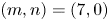 $(m,n) = (7, 0)$,
  $(7, 1)$ and
  $(35, 0)$, respectively. Figure 5(a) shows that with
  $N_{w}$ increasing from 5 to 22, the frequencies and circumferential mode numbers of the excited cut-on modes decrease monotonically.

Figure 5. Variations of (a) the cut-on modes, and (b) the dimensionless acoustic powers generated in the hard-walled duct with  $N_w$.
Further, the dimensionless acoustic powers radiated from the isolated rotor are predicted for  $\Delta \theta _T=0^{\circ }$ and
  $\Delta \theta _T=20^{\circ }$, respectively, as reported in figure 5(b). The added subscript ‘hw’ therein denotes the sound generation in the hard-walled duct. The non-dimensionalization of acoustic energy excludes the linear dependence of the sound field strength on the wake amplitude (which varies with
  $N_w$ according to (3.41) with
  $N_w(\varOmega +\varOmega _w)C_a/U\equiv 6.50$). It should be stressed that for different
  $N_w$ and
  $\Delta \theta _{T}$, the magnitudes of
  $E_{u,hw}$ and
  $E_{d,hw}$ do not indicate the relative significance of the noise reduction under the considered conditions; instead, they reflect the efficiency of the corresponding dipole distributions excited on the rotor blade surfaces as the sound radiators.
Figure 5 reveals that both the sound radiation efficiency and the acoustic energy distribution in the hard-walled duct have a strong dependence on the circumferential periodicity and spanwise phase variation of the oncoming wakes. It then becomes evident that the consideration of the rotating wake excitation contributes greatly to the convenience of our following analysis: it naturally introduces a multimode incident field to the liner, and allows us to investigate the liner effect on the interaction sound field of varying mode and frequency contents as well as different energy distributions by changing  $N_w$ with a fixed reduced frequency
  $\lambda C_a/U$; moreover, considering the phase skewing of the excitation disturbances may help us to explore further the three-dimensional effects in the present flow-acoustic coupling problem.
5.2. Dependence of the sound absorption effect on the liner location
With a focus on the governing noise attenuation mechanisms, we define the porous-material liner (see figure 1b) by the following parameters, which are not optimal but are of practical interest:  $h_{cav}=0.06\ \mbox {m}$,
  $R_f=8000\ \mbox {Rayls}\ \mbox {m}^{-1}$,
  $t_p=0.001\ \mbox {m}$,
  $\zeta =20\,\%$ and
  $d_h=0.001\ \mbox {m}$. The default liner length is taken as
  $L_a=3.0C_a$.
It is known that for realistic turbofan engines, inlet noise reduction is of particular concern. This is not only because of the comparatively limited space in the upstream fan duct for acoustic treatment, but is also due to the fact that the upstream-radiated fan noise, unlike that travelling downstream, is not shielded by complex flows and multiple blade rows. Hence, here we focus on investigating how the acoustic effect of an inlet liner will change as it moves downstream to the over-the-rotor position. With the hard-wall configuration as a baseline, comparisons of the liner effect are made among three different lining locations (see figure 6): (a) the upstream liner with  $x_L^{1}=-4.5C_a$ and
  $x_L^{2}=-1.5C_a$ (referred to as UL-3 with the number ‘3’ indicating that the liner length
  $L_a$ is triple the axial chord length
  $C_a$); (b) the liner with
  $x_L^{1}=-3.0C_a$ and
  $x_L^{2}=0.0C_a$ partially overlapping the rotor (referred to as PO-3); and (c) the liner with
  $x_L^{1}=-2.5C_a$ and
  $x_L^{2}=0.5C_a$ fully overlapping the rotor (referred to as FO-3).

Figure 6. The three liner locations under investigation, where  $L_a=3.0C_a$.
For the given example, a convergence study has been conducted, whose representative results are presented in Appendix C. It is found that for  $N_w$ in the range 5–22, adequate accuracy of the unsteady coupled analysis performed for UL-3 is attained by setting
  $N_m=3$ (with
  $h = -1$, 0 and 1 in (5.1)) and
  $N_n=3$ (with
  $n = 0$, 1 and 2) (see § 3.4). However, the axial overlap of the rotor and the liner makes more cut-off modes engage in their near-field coupling. Hence for PO-3 and FO-3, the setting
  $N_m=3$ and
  $N_n=11$ is used for an accurate determination of the interaction sound field. Also, the blade force expansion (3.11) with
  $N_x=29$ and
  $N_r=13$, as well as the normal particle velocity expansion (3.23) truncated with
  $N_l=50$, are employed in (3.37) to ensure sufficient convergence.
To evaluate respectively the acoustic energy reduction in the upstream and downstream directions, we define the upstream and downstream absorption ratios as  $1 - E_{u}/E_{u,hw}$ and
  $1 - E_{d}/E_{d,hw}$. The total noise reduction resulting from the liner is then characterized by the commonly used sound absorption coefficient
 \begin{equation} {\rm{Absorption}} = 1 - \frac{{{E_u} + {E_d}}}{{{E_{u,hw}} + {E_{d,hw}}}}. \end{equation}
 Figure 7 reveals how the effectiveness of the liner in its absorption of the upstream-radiated sound varies with  $N_w$, with comparisons made among the three different liner locations depicted by figure 6. As is shown in figure 5, the mode and frequency characteristics of the interaction sound field have a direct dependence on
  $N_w$. Thus such a plot provides, to some degree, an indication of the broadband characteristics of the sound-absorbing liner. It is seen that as
  $N_w$ ranges from 5 to 11, all three liners under consideration achieve a remarkably high level of upstream sound absorption, which is more than 90
  $\%$ for both
  $\Delta \theta _T=0^{\circ }$ and
  $\Delta \theta _T=20^{\circ }$. This is not surprising because within this range of
  $N_w$, the ducted sound field is dominated by two zero-radial-order cut-on modes of comparatively high frequencies and large circumferential mode numbers. Such modes are known to contain concentrated acoustic energy near the outer duct wall, which can be absorbed easily by a dissipative wall liner. As
  $N_w$ increases to 12, the mode (
 $h=0,n=1$) becomes cut-on (see figure 5a), leading to an abrupt decrease of sound absorption. In the case of
  $\Delta \theta _T=0^{\circ }$, with
  $N_w$ further increasing from 12 to 22, figure 7(a) shows a progressively rising loss of upstream absorption for PO-3, in comparison with UL-3, which is fully exposed to the upstream sound field. Under the same circumstances, such loss of upstream sound absorption is seen to be suppressed notably by further moving the liner downstream to fully cover the rotor flow path: the largest decrease of the upstream absorption ratio is less than
  $8\,\%$ for FO-3 as compared to UL-3. For
  $\Delta \theta _T=20^{\circ }$, however, different trends are reported in figure 7(b). When the oncoming vortical disturbances possess a spanwise phase variation, for most of the considered range of
  $N_w$, the upstream sound absorption is even increased by moving the upstream liner to the close proximity of the rotor.

Figure 7. Variation of the upstream sound absorption ratio with the circumferential periodicity  $N_w$ of the wake distortion: (a)
  $\Delta \theta _T=0^{\circ }$; (b)
  $\Delta \theta _T=20^{\circ }$.
Moreover, additional acoustic benefits in the downstream direction are gained by the over-the-rotor liners PO-3 and FO-3, as shown by figure 8. Installed in the upstream duct, UL-3 is seen to result in little absorption or even a slight increase of the downstream-transmitted sound. When the inlet liner covers the forward half of the rotor flow path (corresponding to PO-3), appreciable reduction in the downstream-radiated acoustic energy is attained, with the peak absorption over the considered range of  $N_w$ being around
  $31\,\%$ for
  $\Delta \theta _T=0^{\circ }$, and more than
  $50\,\%$ for
  $\Delta \theta _T=20^{\circ }$. The downstream sound absorption is further increased with the liner fully overlapping the rotor, despite a few exceptions seen for
  $\Delta \theta _T=0^{\circ }$ and
  $N_w = 11{-} 15$. Again, the over-the-rotor liners tend to gain more pronounced acoustic benefits under the flow condition where the oncoming wakes impinge on the rotor blades with a skewed phase. In the case of
  $\Delta \theta _T=20^{\circ }$, figure 8(b) reveals that among the three liner configurations considered, FO-3 achieves the highest downstream absorption over the entire range of
  $N_w$, with the peak absorption around
  $80\,\%$ at
  $N_w=6$.

Figure 8. Variation of the downstream sound absorption ratio with the circumferential periodicity  $N_w$ of the wake distortion: (a)
  $\Delta \theta _T=0^{\circ }$; (b)
  $\Delta \theta _T=20^{\circ }$.
Naturally, the combined acoustic effects in both axial directions are reflected in the total sound absorption coefficient. The overall advantage of FO-3 under the varying sound field conditions is shown clearly by figure 9. Also in figure 9, we have compared the sound absorption coefficients of UL-3 predicted by the present method with those by the transfer element method. The latter has been well validated in its ability to analyse the unsteady aerodynamic interaction among separate duct components (Jing, Wang & Sun Reference Jing, Wang and Sun2007; Sun et al. Reference Sun, Wang, Du and Jing2008). Despite some minor deviations of the high-frequency predictions, the overall satisfactory agreement demonstrates the effectiveness of the present method to solve the coupled unsteady responses of the rotor and the liner.

Figure 9. Variation of the total sound absorption coefficient with the circumferential periodicity  $N_w$ of the wake distortion: (a)
  $\Delta \theta _T=0^{\circ }$; (b)
  $\Delta \theta _T=20^{\circ }$.
The above analysis indicates that an over-the-rotor liner can be a promising substitute for conventional inlet acoustic treatment, since it not only effectively attenuates the upstream-radiated noise but also provides additional absorption of the downstream-transmitted sound. As mentioned in the Introduction, such acoustic advantage of over-the-rotor liners at subsonic tip speeds has also been confirmed by the experimental observations of Sutliff et al. (Reference Sutliff, Elliott, Jones and Hartley2009, Reference Sutliff, Jones and Hartley2013).
To capture the physics involved, special attention should be paid to the following two aspects. First, it is noted that not only the absolute sound absorption but also the relative effectiveness of the same liner at different axial positions shows a strong dependence on the circumferential periodicity and spanwise variation of the excitation disturbances. This is indicative of the three-dimensionality of the flow-acoustic coupling between the closely spaced rotor and liner. As was discussed by Namba (Reference Namba1977), the phase skewing of the oncoming wakes tends to increase the spanwise variation of the excited unsteady blade forces; consequently, more cancellation in the sound generation process makes less acoustic energy radiated to the far field (as shown in figure 5b) but more acoustic energy trapped in the vicinity of the rotor. In other words, the portion of the acoustic energy carried by the cut-off modes increases. Compared with the case where  $\Delta \theta _T=0^{\circ }$, the much more pronounced acoustic benefits gained by the over-the-rotor liners with
  $\Delta \theta _T=20^{\circ }$ are thus considered to be associated with the increased contribution from the cut-off modes to the near-field rotor–liner interaction. Second, in the case of
  $\Delta \theta _T=0^{\circ }$, compared with UL-3, PO-3 is seen to result in a significant loss of upstream sound absorption, which is largely recovered with the liner further moving downstream to where FO-3 stands. This is presumably because the increased overlapping area of the rotor and the liner leads to a higher level of their unsteady aerodynamic coupling. In addition, with a termination end within the rotor flow path, PO-3 is likely to result in the acoustic reflections unfavourable for upstream sound absorption.
In what follows, we will examine the above speculations and further explore the noise attenuation mechanisms of the over-the-rotor liner. For illustrative purposes, attention will be restricted to the circumstance where  $N_w=21$ and the IBPA is
  $\sigma = 90^{\circ }$.
5.3. Modifications of the sound field distribution in the lined duct
To throw light on how the liners at different axial positions affect the sound propagation along the duct, a modal analysis of the radiated acoustic energy is first conducted. It is known that only cut-on modes contribute to the axial acoustic energy transmission along the duct. Hence in figures 10 and 11 we plot the dimensionless acoustic powers carried by each cut-on mode propagating away from the isolated rotor in the hard-walled (HW) duct as well as those radiated from the rotor–liner combination for the three liner locations considered, respectively.

Figure 10. Dimensionless modal acoustic powers transmitted (a) upstream and (b) downstream, respectively. Here,  $N_w=21$ and
  $\Delta \theta _T=0^{\circ }$.

Figure 11. Dimensionless modal acoustic powers transmitted (a) upstream and (b) downstream, respectively. Here,  $N_w=21$ and
  $\Delta \theta _T=20^{\circ }$.
For  $\Delta \theta _T=0^{\circ }$, figure 10(a) shows that the upstream liner UL-3 suppresses effectively the upstream-propagating modes
  $(7, 0)$ and
  $(35, 0)$. However, it has little effect on the mode
  $(7, 1)$, which contains the concentrated acoustic energy away from the duct walls. The over-the-rotor liner FO-3 reduces the acoustic energy carried by the upstream-propagating modes
  $(7, 0)$ and
  $(35, 0)$ to a comparable degree, but it almost doubles the upstream-transmitted acoustic energy in the mode
  $(7, 1)$. The increase of the acoustic energy carried by the upstream-propagating mode
  $(7, 1)$ is even more pronounced with the liner partially overlapping the rotor; meanwhile, PO-3 turns out to be less effective in suppressing the dominating mode
  $(7, 0)$ than FO-3 and UL-3. On the other hand, the downstream-transmitted acoustic energy carried by the dominating mode
  $(7,0)$ decreases progressively as the liner moves from the inlet to the over-the-rotor position (see figure 10b). It is interesting to note that although UL-3 and FO-3 have little influence on the downstream-propagating mode
  $(7, 1)$, PO-3 leads to a visible decrease of the acoustic energy contained in this mode. These results indicate that the acoustic energy is not only absorbed but also redistributed among different modes by the liner. Terminating within the rotor flow path, PO-3 causes unwanted reflections to the upstream sound field, which make part of the acoustic energy away from the duct walls and thus escape absorption.
Again, much more pronounced acoustic benefits of the over-the-rotor liners are observed for  $\Delta \theta _T=20^{\circ }$. Figure 11 shows that in this case, FO-3 reduces significantly the acoustic powers transmitted in both directions and by each cut-on mode. PO-3 turns out to be even slightly more effective in absorbing the upstream-radiated sound, but it provides less reduction in the acoustic energy carried by each downstream-propagating mode when compared with FO-3.
To provide a clearer picture of the variations in the sound field distribution, in figures 12 and 13 we plot the contour maps of dimensional sound pressure amplitude on the  $x$–
$x$– $r$ plane for
  $R_{h} \leqslant r \leqslant R_{d}$ and
  $-10.0 C_{a} \leqslant x \leqslant 10.0 C_{a}$. Under the condition that
  $\Delta \theta _T=0^{\circ }$, figure 12(a) reveals relatively high sound pressure close to the outer duct wall in the unlined duct, corresponding to the dominant role played by the mode
  $(7, 0)$ in the sound field. As shown by figure 12(b), with the liner installed upstream of the rotor, the upstream sound pressure is notably attenuated, whereas the near field and the downstream field of the rotor remain almost unchanged. When the liner covers the forward half of the rotor flow path, the sound pressure near the blade tip is locally damped, and meanwhile an evident increase of the sound pressure amplitude near the mid-span and close to the blade leading edge is seen in figure 12(c). Correspondingly, PO-3 appears to reduce the upstream sound pressure near the outer duct wall but increase that in the mid-span. Such observation confirms our previous analysis regarding the mode scatterings and acoustic reflections at the liner termination end within the rotor flow path. When the liner fully overlaps the rotor, however, the unfavourable reflections disappear. Figure 12(d) reveals that FO-3 suppresses effectively the upstream sound propagation and achieves a modest attenuation of the downstream sound field; in addition, it reduces appreciably the high sound pressure near the rotor blade tip.

Figure 12. Sound field distribution along the duct with (a) hard wall, (b) UL-3, (c) PO-3, and (d) FO-3, respectively. The black dashed lines mark the axial positions of the blade leading and trailing edges, and the solid pink rectangle marks the liner location. Here,  $N_w=21$ and
  $\Delta \theta _T=0^{\circ }$.

Figure 13. Sound field distribution along the duct with (a) hard wall, (b) UL-3, (c) PO-3, and (d) FO-3, respectively. Here,  $N_w=21$ and
  $\Delta \theta _T=20^{\circ }$.
For  $\Delta \theta _T=20^{\circ }$, the over-the-rotor liners PO-3 and FO-3 not only significantly suppress the sound propagation in both axial directions but also remarkably reduce the sound pressure in close proximity to the rotor. It is also noted that in this case, the near field in figure 13(a) is of considerable strength, but away from the rotor, the sound field appears to be weaker than depicted by figure 12(a). This demonstrates that due to the phase skewing of the oncoming wakes, the portion of the rotor-radiated acoustic energy carried by the cut-on modes decreases. Therefore, only with the liner installed sufficiently close to the rotor can the considerable amount of acoustic energy trapped in the near field contribute to intensify their flow-acoustic coupling, which may modify notably the unsteady rotor and liner responses.
5.4. Sound source reduction and sound dissipation enhancement
In this subsection, detailed information will be provided on the modified unsteady responses of the rotor and the liner that govern the sound field changes.
First, in figures 14 (for  $\Delta \theta _T=0^{\circ }$) and 15 (for
  $\Delta \theta _T=20^{\circ }$), we plot the unsteady blade loading distribution projected on the
  $x{-}r$ plane for the hard wall and the three liner configurations, respectively. Figure 14(a) reveals that the impingement of the oncoming wakes with zero phase skewing gives rise to a region of high unsteady aerodynamic loading near the blade tip. It is observed from figure 14(b) that UL-3, one axial chord upstream of the rotor, results in marginal changes of the unsteady blade loading distribution. With the porous-material liner installed over the rotor, however, the high tip loading is seen to be reduced effectively, indicating the weakened strengths of the dipole sound sources. Figure 14(c) shows that for PO-3, the tip loading reduction is largely confined to the forward half-chord covered by the lined wall. Fully covering the rotor flow path, FO-3 leads to the tip loading reduction over the entire blade chord, and it also reduces the mid-span loading close to the blade leading edge that is increased by PO-3 (see figure 14(d)).

Figure 14. Unsteady blade loading distribution predicted for (a) hard wall, (b) UL-3, (c) PO-3, and (d) FO-3, respectively. Here,  $N_w=21$ and
  $\Delta \theta _T=0^{\circ }$.
Excited by the oncoming wakes of the phase skewing parameter  $\Delta \theta _T=20^{\circ }$, comparatively high unsteady aerodynamic loading is generated near the blade hub in the hard-walled duct, as shown by figure 15(a). (Note that the discontinuities seen for the loading phase distribution are due to the prescribed phase range of 0 to 2
 ${\rm \pi}$.) It is seen from figures 15(c) and 15(d) that both PO-3 and FO-3 lead to a notable reduction of the unsteady loading magnitude near the blade hub, along with minor variations in the loading phase over the entire blade surface. Again, the reduction of the unsteady tip loading by PO-3 is confined within the forward half-chord. Moreover, in figure 15(b), UL-3 appears to even slightly increase the unsteady blade loading near the hub. This is presumably because the upstream liner reflects a small portion of the upstream-propagating sound backwards, thus giving rise to minor secondary unsteady loading on the rotor blade surfaces.

Figure 15. Unsteady blade loading distribution predicted for (a) hard wall, (b) UL-3, (c) PO-3, and (d) FO-3, respectively. Here,  $N_w=21$ and
  $\Delta \theta _T=20^{\circ }$.
Overall, the above analysis reveals that the assumption of invariant sound sources remains reasonable for a sufficient rotor–liner separation; with an over-the-rotor liner in question, however, the unsteady blade loading in the lined duct can differ significantly from its rigid duct value. The sound source modifications on the rotor blades due to the presence of an over-the-rotor liner have also been evidenced by experimental observations (Sutliff et al. Reference Sutliff, Dougherty and Walker2010). It is widely believed that it is the secondary flows near the blade tips that make the foam–metal liner act as a pressure release surface for the fan rotor beneath it (Sutliff & Jones Reference Sutliff and Jones2009). However, with no account taken of the tip clearance flows in our model, the present results indicate that the near-field rotor–liner interaction through the ducted sound field can also contribute to a noticeable reduction of the unsteady blade loading. Moreover, figures 14 and 15 confirm that the unsteady pressure release can occur not only near the blade tip but also near the hub. Therefore, the sound source modification due to the over-the-rotor acoustic treatment cannot be viewed simply as a localized phenomenon. Only by capturing the systematic variation in the unsteady blade loading distribution can one accurately predict the over-the-rotor liner effect.
Further, to throw light on the changes in unsteady liner response, we plot the normal particle velocity distributions over the lined wall, generated in response to each dominating circumferential mode, in figure 16 for  $\Delta \theta _T=0^{\circ }$ and figure 17 for
  $\Delta \theta _T=20^{\circ }$. In both cases, the magnitude of the fluctuating normal particle velocity on the liner surface is increased considerably due to the axial overlap of the rotor and the liner, with an evident peak existing near the blade leading edge. This observation can be interpreted as follows. The relatively high-amplitude unsteady pressure in the close proximity of the rotor, especially near the blade leading edge, intensifies significantly the fluid particle oscillation through the over-the-rotor lined wall. A direct consequence is the higher sound absorption by the liner: more acoustic energy is spent on the excitation of periodic vortex shedding at the rims of the holes in the perforated screen, and the mechanical energy is subsequently dissipated into heat; meanwhile, an increased amount of sound is scattered into the back cavity and absorbed by the porous material. Furthermore, the intensified mass sources will also excite a stronger liner-scattering sound field within the main duct. This field superposes on the rotor-scattering sound field excited by the actual unsteady blade loading to form the interaction sound field inside the duct. Hence with inappropriate distribution, an over-the-rotor liner may also cause some unfavourable sound scatterings and reflections. An example of this is PO-3 under the circumstance where
  $N_w=21$ and
  $\Delta \theta _T=0^{\circ }$; in light of the results discussed earlier, the second velocity peak observed in figure 16(b), as high as that near the blade leading edge, is possibly associated with the strong acoustic reflections from the liner termination end at the mid-chord.

Figure 16. Distribution of the normal particle velocity amplitude over the lined wall, for (a) UL-3, (b) PO-3, and (c) FO-3, respectively. Here,  $N_w=21$ and
  $\Delta \theta _T=0^{\circ }$.

Figure 17. Distribution of the normal particle velocity amplitude over the lined wall, for (a) UL-3, (b) PO-3, and (c) FO-3, respectively. Here,  $N_w=21$ and
  $\Delta \theta _T=20^{\circ }$.
5.5. Effectiveness of the over-the-rotor acoustic treatment with shortened axial length
From the above analyses, one can conclude that the two mechanisms governing the acoustic benefits gained by an over-the-rotor liner are sound source reduction and sound dissipation enhancement. It is sensible to explore further whether or not by installing the sound-absorbing liner over the rotor, and making use of their flow-acoustic coupling effects, the liner length can be shortened without significant acoustic penalty. To this end, we develop a comparative analysis additionally considering two over-the-rotor liners with the same configuration but shortened axial lengths (see figure 18): the two-axial-chord-length liner FO-2 with  $x_L^{1}=-1.5C_a$ and
  $x_L^{2}=0.5C_a$, and the liner FO-1 with
  $x_L^{1}=-0.5C_a$ and
  $x_L^{2}=0.5C_a$ just covering the rotor flow path. For brevity, only the results obtained for
  $N_w = 21$ and
  $\Delta \theta _T=20^{\circ }$ will be discussed.

Figure 18. The over-the-rotor liners of the shortened axial lengths: (a)  $L_a=2.0C_a$; (b)
  $L_a=1.0C_a$.
The upstream and downstream absorption ratios as well as the total sound absorption coefficients for the five liner configurations considered are listed in table 1. Reducing the upstream-radiated acoustic energy by  $67.5\,\%$ and the downstream-radiated acoustic energy by
  $68.8\,\%$, FO-2 can be regarded as a reasonable substitute for UL-3, and even for FO-3 in view of the saved axial space. However, the one-axial-chord-length liner FO-1 appears to be not so satisfactory, as it provides upstream absorption as low as
  $18.6\,\%$. Further, for the over-the-rotor liners of different axial extents, comparisons of the sound field distributions, the unsteady blade loading distributions and the normal particle velocity distributions on the lined wall are made in figures 19–21, respectively. Compared with FO-3, FO-2 and FO-1 are seen to alleviate the unsteady blade loading to a comparable degree (see figures 15(d) and 20). This accounts for their marginal loss of downstream sound absorption. Nevertheless, figure 21 shows that with the upstream length of the over-the-rotor liner shortened, the peak amplitude of the fluctuating normal particle velocity on the liner surface drops considerably. The weaker fluid particle oscillation through the shorter lined wall is indicative of a decreased amount of sound dissipated by the liner. Besides, near the upstream end of FO-1, which coincides axially with the blade leading edge, the normal particle velocity on the lined wall shows a sharp increase. Meanwhile, it is observed from figure 19 that FO-1 reduces the sound pressure near the mid-span, but somewhat increases the upstream sound pressure near the outer duct wall. It seems likely that as the upstream end of the liner approaches the blade leading edge, strong reflections and scatterings set up at the axial interface of impedance discontinuity and direct part of the interaction noise to the upstream duct.
Table 1. Sound absorption under the circumstance where  $N_w=21$ and
  $\Delta \theta _T=20^{\circ }$.


Figure 19. Sound field distribution along the duct with (a) hard wall, (b) FO-1, (c) FO-2, and (d) FO-3, respectively. Here,  $N_w=21$ and
  $\Delta \theta _T=20^{\circ }$.

Figure 20. Unsteady blade loading distribution predicted for (a) FO-1 and (b) FO-2, respectively. Here,  $N_w=21$ and
  $\Delta \theta _T=20^{\circ }$.

Figure 21. Distribution of the normal particle velocity amplitude over the lined wall, for (a) FO-1, (b) FO-2, and (c) FO-3, respectively. Here,  $N_w=21$ and
  $\Delta \theta _T=20^{\circ }$.
6. Conclusions
In this paper, we conduct a theoretical investigation, within the linear scope, on the acoustic effect of an over-the-rotor liner as well as the noise attenuation mechanisms behind. In the ideal case of an infinite annular duct containing uniform subsonic flow, the three-dimensional flow-acoustic coupling between a fan rotor and a porous-material liner is analysed through the simultaneous solution to their coupled unsteady responses. An illustrative case considering the noise generation due to the interaction of rotor blades with oncoming wake distortions has been discussed. On the basis of the obtained results, the following conclusions are reached.
Under various sound field conditions, moving the inlet liner to the over-the-rotor location is shown to result in a marginal loss or even an increase of upstream noise reduction; in most cases, this is accompanied by an additional absorption of the downstream-transmitted noise. The decreased spacing or increased overlapping area between the rotor and the liner typically translates to the raised level of their flow-acoustic coupling. This is because apart from the cut-on modes, least damped cut-off modes also engage in the near-field rotor–liner interaction. The acoustic impact of the axial overlap of rotor and liner, therefore, has a direct dependence on the energy distribution in the primary sound field, which is affected strongly by the three-dimensional variation of the excitation disturbances.
The acoustic benefits gained by an over-the-rotor liner are attributed to two fundamental noise attenuation mechanisms: sound source reduction and sound dissipation enhancement.
With no account taken of the secondary flow effects in our model, the present analyses still reveal the notable alleviation of the unsteady blade loading due to the sound-absorbing liner installed over the rotor. This implies that apart from the possible contributions from the tip flow changes detected experimentally, the unsteady rotor–liner interaction through the ducted sound field also makes the foam–metal liner act as a pressure release surface for the rotor beneath it. Moreover, the reduction in unsteady aerodynamic loading does not always occur near the blade tip. Thus it cannot be viewed simply as a localized phenomenon. Only by capturing the sound source modifications over the entire blade surfaces can one accurately predict the acoustic effect of an over-the-rotor liner.
In close proximity to the rotor, the high-amplitude unsteady pressure intensifies significantly the fluid particle oscillation through the acoustically treated wall. On the one hand, this leads to an increased amount of sound dissipated by the liner, especially in the presence of the sound-absorbing material in its back cavity. On the other hand, the over-the-rotor liner also gives rise to more sound scatterings into the main duct. Its influence on the noise radiation can be determined only by evaluating the superimposed contributions from the rotor and the liner to the interaction sound field. Great care thus must be taken for the over-the-rotor acoustic treatment design with a liner end within the rotor flow path or close to a blade leading edge, since unwanted reflections at the axial interface of impedance discontinuity may be triggered by the strong acoustic excitation therein.
Finally, we extend the discussion to throw light on the influence of shortening the liner length. It is shown that the inlet liner fully covering the rotor but extending upstream with a reduced axial length leads to a similar degree of sound source reduction; however, a trade-off between the liner length and the amount of sound dissipated by the liner seems inevitable.
Note that many complicating factors, including mean loading acting on rotor blades, viscous boundary layer over the lining, and high acoustic intensity in the vicinity of a fan rotor, have been neglected in this simplified interaction model. Taking these factors into account may modify the predictions to a varying degree; however, the findings regarding the governing interaction mechanisms and the basic effect trends will not be challenged.
Funding
This work was supported by the National Natural Science Foundation of China (grant nos 51790514, 52022009) and the National Science and Technology Major Project (grant no. 2017-II-003-0015).
Declaration of interests
The authors report no conflict of interest.
Appendix A. The impedance model for the porous-material liner
According to Scott (Reference Scott1946), a uniform, i.e. isotropic and homogeneous, porous material can be modelled acoustically as an equivalent fluid. Its acoustic properties are often formulated by the empirical power law of Delany & Bazley (Reference Delany and Bazley1970) as the power functions of  $f/R_f$ with the constant coefficients fitted from experimental data. Here,
  $f=\omega /2{\rm \pi}$ is the frequency of the incident sound. In view of the material-dependent character of the equivalent fluid properties, and also due to the lack of acoustic data for foam–metals in the open literature, the empirical equivalent fluid model used by Selamet et al. (Reference Selamet, Xu, Lee and Huff2004) for a perforated liner filled with fibrous material has been employed in the present study. In this model, the complex-valued characteristic impedance
  $Z_e = \rho _{e} c_{e}$ and wavenumber
  $k_e = \omega / c_{e}$ of the fibrous material have the forms
 $$\begin{gather} \frac{Z_{e}}{\rho_{0} c_{0}} = \left[ 1 + 0.0855 \left( \frac{f}{R_f} \right)^{{-}0.754} \right] + \mathrm{i} \left[ - 0.0765 \left( \frac{f}{R_f} \right)^{{-}0.732} \right], \end{gather}$$
 $$\begin{gather}\frac{k_{e}}{k_{0}} = \left[ 1 + 0.1472 \left( \frac{f}{R_f} \right)^{{-}0.577} \right] + \mathrm{i} \left[ - 0.1734 \left( \frac{f}{R_f} \right)^{{-}0.595} \right]. \end{gather}$$
Further, the specific impedance of the perforated plate is given by
 \begin{equation} {Z_p} = \frac{1}{\zeta }\left\{ {0.006 + {\rm i}{k_0}\left[ {{t_p} + 0.375{d_h}\left( {1 + \frac{{{Z_e}}}{{{\rho_{0}c_{0}}}}\,\frac{{{k_e}}}{{{k_0}}}} \right)} \right]} \right\}. \end{equation}
Appendix B. The axial wavenumbers of the hard-walled duct modes
The axial wavenumbers of the acoustic modes for an annular hard-walled duct and those of the convected vortical waves are defined respectively by
 \begin{equation} \gamma_{mn}^{{\pm}} = \frac{M_{a} k_{0} \pm \kappa_{n,m}}{1-M_{a}^{2}},\quad \gamma_{v} ={-}\frac{\omega}{U}, \end{equation}
where
 \begin{equation} \kappa_{n,m} = \left\{\begin{array}{ll} \sqrt{k_{0}^{2} - ( 1 - M_{a}^{2} ) k_{mn}^{2} }, & \mbox{for } k_{0}^{2} \geqslant ( 1 - M_{a}^{2} ) k_{mn}^{2} \mbox{ (cut-on)}, \\ -\mathrm{i}\sqrt{( 1 - M_{a}^{2} ) k_{mn}^{2} - k_{0}^{2}}, & \mbox{for } k_{0}^{2} < ( 1 - M_{a}^{2} ) k_{mn}^{2} \mbox{ (cut-off)}. \end{array} \right. \end{equation}
Appendix C. The convergence study
The convergence tests of the rotor-alone prediction, the liner-alone prediction and the unsteady coupled analysis for the rotor–liner interaction are presented below.
First, over the considered range of  $N_w$, figures 22 and 23 show the prediction results of the dimensionless acoustic powers generated by the wake–rotor interaction in the hard-walled duct with an increasing number of collocation points on the blade surface (also the increasing orders of the unsteady blade force expansion, see (3.11)). Based on the given results, the setting
  $N_x=29$ and
  $N_r=13$ has been used to predict the unsteady rotor response.

Figure 22. Predictions of the dimensionless acoustic powers radiated by the isolated rotor subject to the impingement of oncoming wakes in the infinite hard-walled duct, with increasing  $N_x$ and fixed
  $N_r = 13$: (a)
  $\Delta \theta _T=0^{\circ }$; (b)
  $\Delta \theta _T=20^{\circ }$.

Figure 23. Predictions of the dimensionless acoustic powers radiated by the isolated rotor subject to the impingement of oncoming wakes in the infinite hard-walled duct, with increasing  $N_r$ and fixed
  $N_x = 29$: (a)
  $\Delta \theta _T=0^{\circ }$; (b)
  $\Delta \theta _T=20^{\circ }$.
Second, figure 24 shows the sound absorption coefficient of the isolated liner predicted with increasing  $N_l$, the order of the truncated sine expansion of the normal acoustic particle velocity
  $V_r$ through the lined wall (see (3.23)). Taking
  $N_w=21$, for example, we consider that a single upstream-propagating acoustic mode, corresponding to each cut-on mode that would be generated by the wake–rotor interaction, is incident from downstream. Note that due to the convection effect, the upstream-propagating mode has a shorter wavelength compared to the corresponding downstream-propagating mode, thus a larger
  $N_l$ is required to ensure the accurate prediction of the unsteady liner response. Calculations indicate that with
  $N_l$ set to be 50, the relative errors of the predicted sound absorption coefficients for the three cut-on modes in this case, as compared to the predictions made with
  $N_l=100$, are all less than
  $0.6\,\%$.

Figure 24. Predictions of the sound absorption coefficient of the isolated liner with increasing  $N_l$. Consider that a single upstream-propagating mode
  $(m,n)$, corresponding to each cut-on mode that would be generated by the wake–rotor interaction in the case of
  $N_w = 21$, is incident from downstream.
Finally, the convergence of the unsteady coupled analysis for the rotor–liner interaction is examined. The representative results for  $N_w=21$ and
  $\Delta \theta _T=20^{\circ }$ are given in figure 25, with the selected value of
  $(N_m,N_n)$ in (3.37) marked by the cross. Here,
  $N_m=2$ means that only the contribution from the acoustic modes of the harmonic numbers
  $h=0$ and 1 and the radial orders
  $n = 0, \ldots, N_{n} - 1$ to the rotor–liner interaction are taken into account; accordingly,
  $N_m=3$ corresponds to
  $h=0$,
  $\pm 1$, and
  $N_m=5$ corresponds to
  $h=0$,
  $\pm 1$ and
  $\pm 2$ (see (5.1)).

Figure 25. Predictions of the dimensionless (a) upstream-transmitted and (b) downstream-transmitted acoustic powers radiated from the rotor–liner combination with different numbers of acoustic modes retained in the unsteady coupled analysis. Here,  $N_w = 21$ and
  $\Delta \theta _T=20^{\circ }$.


