


1. INTRODUCTION
Owing to the development of chirped pulse amplification technology, various laser–electron acceleration schemes have been proposed (Tajima & Dawson, Reference Tajima and Dawson1979; Harternann et al., Reference Harternann, Fochs, Sage, Luhmann, Woodworth, Perry, Chen and Kerman1995; Esarey et al., Reference Esarey, Sprangle, Krall and Ting1996; Pukhov et al., Reference Pukhov, Sheng and Meyer-Ter-vehn1999; Gupta et al., Reference Gupta, Kant, Kim and Suk2007; Ghotra & Kant, Reference Ghotra and Kant2016c ), aiming at compact and low-cost high-energy electron accelerators. Generally, these schemes can be divided into two regimes: in plasma (Tajima & Dawson, Reference Tajima and Dawson1979; Esarey et al., Reference Esarey, Sprangle, Krall and Ting1996; Pukhov et al., Reference Pukhov, Sheng and Meyer-Ter-vehn1999; Ghotra & Kant, Reference Ghotra and Kant2016c ) and in vacuum (KawaTa et al., Reference Kawata, Maruyama, Watanabe and Takahashi1991; Harternann et al., Reference Harternann, Fochs, Sage, Luhmann, Woodworth, Perry, Chen and Kerman1995; Malka et al., Reference Malka, Lefebvre and Miquel1997; Salamin & Faisal, Reference Salamin and Faisal1997; Gupta et al., Reference Gupta, Kant, Kim and Suk2007). The laser–plasma-based electron accelerators have now been able to produce a high-quality electron bunch with energy ~ GeV owing to the huge acceleration gradient in laser wakefield (Lu et al., Reference Lu, Tzoufras, Joshi, Tsung, Mori, Vieira, Fonseca and Silva2007; Xiaoming Wang et al., Reference Xiaomingwang, Zgadzaj, Fazel, Li, Yi, Zhang, Henderson, Chang, Korzekwa, Tsai, Pai, Quevedo, Dyer, Gaul, Martinez, Bernstein, Borger, Spinks, Donovan, Khudik, Shvets, Ditmire and Downer2013; Leemans et al., Reference Leemans, Gonsalves, Mao, Nakamura, Benedetti, Schroeder, Tóth, Daniels, Mittelberger, Bulanov, Vay, Geddes and Esarey2014); but they have to face problems like the inherent interaction instability between laser and plasma. In the vacuum regime, electrons cannot be accelerated by a plane electromagnetic wave because of the symmetry in space and time (Gibbon, Reference Gibbon2005). To break this symmetry and gain kinetic energy, there are two ways. One locates at the usage of different lasers, such as pulsed radially polarized laser (Gupta et al., Reference Gupta, Kant, Kim and Suk2007; Wong & Kärtner, Reference Wong and Kärtner2010; Ghotra & Kant, Reference Ghotra and Kant2016b ); or a strongly focused laser pulse, which can lead to ponderomotive scattering of electrons (Harternann et al., Reference Harternann, Fochs, Sage, Luhmann, Woodworth, Perry, Chen and Kerman1995; Malka et al., Reference Malka, Lefebvre and Miquel1997; Quesnel & Mora, Reference Quesnel and Mora1998); or an ultra-intense laser, in which the capture and acceleration scenario (CAS) mechanism occurs (Pang et al., Reference Pang, Ho, Yuan, Cao, Kong, Wang and Shao2002; Wang et al., Reference Wang, Ho, Yuan, Kong, Cao, Shao, Sessler, Esarey, Moshkovich, Nishida, Yugami, Ito, Wang and Scheid2002). The other one is to introduce an extra field. The earliest attempt was to impose an additional perpendicular weak static electric field, which promotes the acceleration gradient to ~ GV/m (Kawata et al., Reference Kawata, Maruyama, Watanabe and Takahashi1991). An extra transverse magnetic field is also thought to be helpful by enhancing the v × B force and breaking the symmetry of acceleration and deceleration phases (Gupta & Ryu, Reference Gupta and Ryu2005; Chen et al., Reference Chen, Ho, Kong, Wang, Wang and Xu2007). An azimuthal magnetic field turned to show its charm when combined with laser field (Ghotra & Kant, Reference Ghotra and Kant2015). More attractively, when a background of longitudinal magnetic field exists, resonant acceleration will occur, and the energy gains significantly. Although K.P. Singh found this phenomenon when numerically analyzing the dynamics of electrons in plasma (Singh, Reference Singh2004), the resonant condition was not given. An approximate analytical solution was soon given by Liu (Liu et al., Reference Liu, He and Chen2004). However, the resonant reason is still not clear. More importantly, the previous works were aimed at fast ignition where only several megaelectronvolt (MeV) electrons are desired. The capability of laser-magnetic resonance acceleration (LMRA), accelerating electrons in a gradient of ~ GV/cm in vacuum, was not recognized.
On the other hand, at the age of these researches, a method to generate kT scale magnetic field in laboratory was missing; hence, LMRA in vacuum seemed to be far to carry out. Recently, a millimeter-long, nano-seconds, and kilo-tesla magnetic field with transverse size ~ 1 mm can be realized by irradiating two laser beams on to a capacitor-coil target (Fujioka et al., Reference Fujioka, Zhang, Ishihara, Shigemori, Hironaka, Johzaki, Sunahara, Yamamoto, Nakashima, Watanabe, Shiraga, Nishimura and Azechi2013). This sheds a light on the table-top laser-driven electron accelerators based on LMRA.
In this paper, we investigated this mechanism carefully; give a detailed discussion on the reason of resonance; and deduce an exact analytic γ factor and acceleration gradient of a test electron on the resonant point. We also investigate the acceleration of electron bunches under a laboratory-condition magnetic field and a strongly focused laser field using an electron bunch radiation code. The simulation results show that electrons can be effectively accelerated in GV/cm scale with a good monochromaticity and collimation.
2. MOTION OF TEST ELECTRON IN PLANE WAVE WITH EXTRA B-FIELD
We start from the most basic case, where a test electron moves in the combined fields of an extra longitudinal magnetic field B ex = B 0 e z and a plane wave field. The plane wave propagates along the z-axes, and its vector potential is represented by
 $${\bf A} = \displaystyle{{mca_0} \over e}(\sin {\rm \alpha} \sin {\rm \phi},\;\cos {\rm \alpha} \cos {\rm \phi},\;0).$$
Here
 $a_0 = (eE_0/m{\rm \omega} _{\rm L}c) = \sqrt {[I{\rm (W/c}{\rm m}^{\rm 2}{\rm )}{\rm \lambda} ^{\rm 2}{\rm (\mu m)}]/(1.37 \times {10}^{18})} $
is the dimensionless amplitude of laser. E
0 is the peak value of electric field. ϕ = ωL
t − kL
z + ϕ00 is the phase, and ωL the frequency; α describes the polarization of laser; α being 0 or π/2 means a linearly polarized laser with its polarization direction along y or x-direction, and for a right-/left-hand circularly polarized laser, α = ± π/4.
$a_0 = (eE_0/m{\rm \omega} _{\rm L}c) = \sqrt {[I{\rm (W/c}{\rm m}^{\rm 2}{\rm )}{\rm \lambda} ^{\rm 2}{\rm (\mu m)}]/(1.37 \times {10}^{18})} $
is the dimensionless amplitude of laser. E
0 is the peak value of electric field. ϕ = ωL
t − kL
z + ϕ00 is the phase, and ωL the frequency; α describes the polarization of laser; α being 0 or π/2 means a linearly polarized laser with its polarization direction along y or x-direction, and for a right-/left-hand circularly polarized laser, α = ± π/4.
Suppose the whole system is in free space, the electron motion is governed by the relativistic Lorentz equation
 $$\displaystyle{{{\rm d}{\bi p}} \over {{\rm d}t}} = - e({\bi E} + {\bi v} \times {\bi B} + {\bi v} \times {\bi B}_{{\bf ex}}), $$
where
p
= γm
v
;
E
= −(∂A
/
∂t) and
 ${\bi B} = \nabla \times {\bi A}$
are electric and magnetic field of the laser. In components, Eq. (2) is written as
${\bi B} = \nabla \times {\bi A}$
are electric and magnetic field of the laser. In components, Eq. (2) is written as
 $$\displaystyle{{\rm d} \over {{\rm d}t}}(\,p_x - eA_x) = - eB_0v_y,$$
 $$\displaystyle{{\rm d} \over {{\rm d}t}}(\,p_y - eA_y) = eB_0v_x,$$
 $$\displaystyle{{{\rm d}p_z} \over {{\rm d}t}} = - e{\bi v} \cdot \!\displaystyle{{\partial {\bf A}} \over {\partial z}}.$$
Together with the energy equation
 $$mc^2\displaystyle{{{\rm d\gamma}} \over {{\rm d}t}} = {\bi v} \cdot \!\displaystyle{{{\rm d}{\bi p}} \over {{\rm d}t}} = e{\bi v}\cdot \!\displaystyle{{\partial {\bf A}} \over {\partial t}},$$
and considering ωL = k L c, it is not difficult to get the z-component of momentum
 $$p_z = mc({\rm \gamma} - {\rm \kappa} _{z0}),$$
where κ z0 = γ0(1 − (v z0/c)) is the Doppler factor. It depends only on the initial state of electron. However, the x and y-components in Eq. (3) are coupled with each other. In order to solve the equations, we turn to the space of ϕ. Note that
 $$\displaystyle{{\rm d} \over {{\rm d}t}} = \displaystyle{{\rm d} \over {{\rm d}{\rm \phi}}} \displaystyle{{{\rm d}{\rm \phi}} \over {{\rm d}t}} = ({\rm \omega} _{\rm L} - k_{\rm L}v_z)\displaystyle{{\rm d} \over {{\rm d}{\rm \phi}}} = \displaystyle{{{\rm \omega} _{\rm L}{\rm \kappa} _{z0}} \over {\rm \gamma}} \displaystyle{{\rm d} \over {{\rm d}{\rm \phi}}}, $$
where Eq. (5) is used; ωLκ z0/γ is the laser frequency that electron feels under laboratory frame. Including Eq. (6), the x- and y-components in Eq. (3) can be rewritten as
 $$\displaystyle{{{\rm d}^2p_x} \over {{\rm d}{\rm \phi} ^2}} + \Omega ^2p_x = (\Omega \cos {\rm \alpha} - \sin {\rm \alpha} )mca_0\sin {\rm \phi},$$
 $$\displaystyle{{{\rm d}^2p_y} \over {{\rm d}{\rm \phi} ^2}} + \Omega ^2p_y = (\Omega \sin {\rm \alpha} - \cos {\rm \alpha} )mca_0\cos {\rm \phi}.$$
Here Ω = (eB 0/mωLκ z0) is the normalized relativistic cyclotron frequency in the extra B-field by ωLκ z0/γ, and can be regarded as the intrinsic frequency of the system.
Equation (7) is the equation of motion of a particle driven by an external force with dimensionless frequency 1. When the intrinsic frequency matches the driver frequency, namely
 $$\left \vert {\rm \Omega} \right \vert = 1,$$
resonance occurs. However, under some specific cases, such as Ω = 1 and α = π/4, or Ω = −1 and α = −π/4, the driver vanishes. As a result, Eq. (7) degenerates to simple oscillating functions. The transverse momentum oscillates sinusoidally. This indicates that for a right-hand circularly polarized laser, only an antiparallel magnetic field can lead to resonance; and for a left-hand one, a parallel magnetic field is needed; but for a linearly polarized laser (α = 0 or π/2), the driver exists all the time, and the resonance occurs at Ω = ±1, which means that both parallel and antiparallel magnetic fields are available for resonant acceleration.
As for the resonant condition expressed by Eq. (8), it is not easy to realize. For an electron initially at rest (κ z0 = 1), the matched magnetic field is as high as mωL/e ≈ 104 T. Such strong magnetic field exists in dense plasma irradiated by ultra-intense lasers, but far from realization in a vacuum with presently available technology; but if the electron has an initial velocity along the laser propagating direction, the matched magnetic field strength decreases with κ z0, for example, if the electron initial energy changes to 3 MeV, the required magnetic field is reduced to 866.82 T. In ultra-relativistic limit (p z0 ≫ 1), the matched magnetic field is inversely proportional to p z0 (Singh, Reference Singh2006). Besides, Eq. (8) indicates that for the same electron energy, the matched magnetic field varies with the distribution of initial velocity between the transverse and the longitudinal direction. This means that, under the same extra B-field, the injection angle affects the acceleration greatly (Ghotra & Kant, Reference Ghotra and Kant2016a ). Another important feature of the resonant condition is that it is independent of a 0, which means the envelope of laser does not affect the resonance much.
To get a strict solution of Eq. (7), we start with the general case. If |Ω| ≠ 1, and the initial electron location and momentum are (x 0, y 0, z 0) and (p x0, p y0, p z0). Then p x and p y are
 $$p_x = C_{0x}\sin {\rm \phi} + C_{1x}\sin (\Omega {\rm \phi} ) + C_{2x}\cos (\Omega {\rm \phi} ),$$
 $$p_y = C_{0y}\cos {\rm \phi} + C_{1y}\cos (\Omega {\rm \phi} ) + C_{2y}\sin (\Omega {\rm \phi} ).$$
Here
 $$C_{0x} = mca_0\displaystyle{{\Omega \cos {\rm \alpha} - \sin {\rm \alpha}} \over {\Omega ^2 - 1}},C_{0y} = mca_0\displaystyle{{\Omega \sin {\rm \alpha} - \cos {\rm \alpha}} \over {\Omega ^2 - 1}},$$
 $$\eqalign{\left( {\matrix{ {C_{1x}} \cr {C_{2x}} \cr}} \right) & = \left( {\matrix{ { - C_{1y}} \cr {C_{2y}} \cr}} \right) \cr & = \left( {\matrix{ {\sin {\hat {\rm \phi}} _0} & { - \cos {\hat {\rm \phi}} _0} \cr {\cos {\hat {\rm \phi}} _0} & {\sin {\hat {\rm \phi}} _0} \cr}} \right)\left( {\matrix{ {\,p_{x0} - C_{0x}\sin {\rm \phi} _0} \cr {\,p_{y0} - C_{0y}\cos {\rm \phi} _0} \cr}} \right),}$$
and ϕ0 = ϕ00 − k
L
z
0, is the initial phase.
 $\hat {\rm \phi} _0 = {\rm \Omega} {\rm \phi} _0$
. The coefficients C
0x
and C
0y
approach infinity when |Ω| → 1, which agrees with the resonant condition. Despite of infinite C
0x
and C
0y
, p
x
, and p
y
are finite in this limit. Using L'Hospital's rule, we can get the exact transverse momentum on the resonant point
$\hat {\rm \phi} _0 = {\rm \Omega} {\rm \phi} _0$
. The coefficients C
0x
and C
0y
approach infinity when |Ω| → 1, which agrees with the resonant condition. Despite of infinite C
0x
and C
0y
, p
x
, and p
y
are finite in this limit. Using L'Hospital's rule, we can get the exact transverse momentum on the resonant point
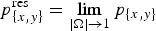 $p_{\left\{ {x,y} \right\}}^{{\rm res}} = \mathop {\lim} \limits_{\left\vert \Omega \right\vert \to 1} p_{\left\{ {x,y} \right\}}$
, and the corresponding γ factor
$p_{\left\{ {x,y} \right\}}^{{\rm res}} = \mathop {\lim} \limits_{\left\vert \Omega \right\vert \to 1} p_{\left\{ {x,y} \right\}}$
, and the corresponding γ factor
 $${\rm \gamma} ^{{\rm res}} = \left[ {1 + {\left( {\displaystyle{{{\bi p}^{{\rm res}}} \over {mc}}} \right)}^2} \right]^{\displaystyle{1 \over 2}}.$$
2.1. Circular polarization
For an electron interacting with a left-hand circularly polarized laser (α = −π/4), both p x and p y oscillate at the intrinsic frequency. This indicates that the transverse velocity of electron rotates around the z-axis. As Figure 1a shows, the angle between electron transverse velocity v ⊥ and x-axis can be written as
 $$\arctan \displaystyle{{v_y} \over {v_x}} = {\rm \phi} + {\rm \theta} _ \bot = \int_0^t \displaystyle{{{\rm \omega} _{\rm L}{\rm \kappa} _{z0}} \over {{\rm \gamma} ({t}^{\prime})}}{\rm d}{t}^{\prime} + \arctan \displaystyle{{v_{ \bot E}} \over {v_{{\rm \parallel} E}}}.$$

Fig. 1. Schematic representation of resonance.
In the rotating reference frame with laser electric field, θ⊥ is
 $${\rm \theta} _ \bot = \arctan \displaystyle{{\,p_{ \bot y0}} \over {(\sqrt 2 /2)a_0({\rm \phi} _0 - {\rm \phi} ) + p_{ \bot x0}}}.$$
Here, p ⊥y0 = (p y0/mc)cosϕ0 − (p x0/mc)sinϕ0 is the initial momentum perpendicular to laser electric field; p ⊥x0 = (p x0/mc)cosϕ0 + (p y0/mc)sinϕ0 is the initial momentum along the laser electric field. Figure 1b shows the evolution of θ⊥ under different ϕ0. The initial electron transverse velocity is along x axis, the initial angle between electron transverse velocity and laser electric field is ϕ0. The 0 < ϕ0 < π indicates that the laser electric field rotates before electron transverse velocity. In this case, θ⊥ increases quickly toward π. If π < ϕ0 < 2π, the laser electric field rotates after electron transverse velocity, and θ⊥ decreases toward π in a short time. After that, electron transverse velocity v ⊥ keeps almost antiparallel with laser electric field all the time. They both rotate at a frequency of (ωLκ z0/γ), as shown in Figure 1c, which means the completely matching between the laser frequency that electron feels under laboratory frame and relativistic cyclotron frequency.
Substituting Eqs. (5) and (9) into Eq. (10), we can get the corresponding resonant γ factor
 $${\rm \gamma} ^{{\rm res}} = {\rm \gamma} _0 + \displaystyle{1 \over {4{\rm \kappa} _{z0}}}\left[ {a_0^2 {({\rm \phi} - {\rm \phi}_0)}^2 - 2\sqrt 2 a_0p_{ \bot x0}({\rm \phi} - {\rm \phi} _0)} \right].$$
If the initial momentum along the laser electric field is small, the energy is roughly proportional to the square of phase difference between laser and electron. However, for a large p ⊥x0, the electron loses energy first. When π/2 < θ⊥ < 3π/2, v · E < 0, it starts to soak up energy from laser fields, shown as Figure 2. This process is called self-modulation stabilization.

Fig. 2. The process of self-modulation stabilization in circularly polarized laser fields. p x0 = 40 mc, p y0 = 0, ϕ0 = 0, and a 0 = 10. (a) v · E as a function of ϕ. (b) Lorentz factor of electron. Electron lies in the phase of losing energy (green domain) at the beginning; but after θ⊥ increases to π/2, the electron moves into the accelerating phase, getting energy from laser fields continuously.
To get the mean acceleration gradient, we integrate the momentum p z to get electron longitudinal displacement
 $$z - z_0 = \displaystyle{1 \over {2k_{\rm L}{\rm \kappa} _{z0}^2}} \left[ {1 - {\rm \kappa} _{z0}^2 + \displaystyle{1 \over 6}a_0^2 {({\rm \phi} - {\rm \phi} _0)}^2} \right]({\rm \phi} - {\rm \phi} _0),$$
here, we have assumed p
⊥x0 ≪ 1. Including Eq. (13), and when
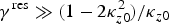 ${\rm \gamma} ^{{\rm res}}{\rm \;\gg}\; (1 - 2{\rm \kappa} _{z0}^2 )/{\rm \kappa} _{z0}$
, the mean acceleration gradient is expressed as
${\rm \gamma} ^{{\rm res}}{\rm \;\gg}\; (1 - 2{\rm \kappa} _{z0}^2 )/{\rm \kappa} _{z0}$
, the mean acceleration gradient is expressed as
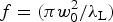
 $$\overline {\displaystyle{{{\rm d}{\rm \gamma} ^{{\rm res}}} \over {{\rm d}z}}} = \displaystyle{{{\rm \gamma} ^{{\rm res}} - {\rm \gamma} _0} \over {z - z_0}} \approx \left( {\displaystyle{{3{\rm \pi \kappa} _{z0}^{1/2} a_0} \over {{\rm \lambda} _L}}} \right)^{\textstyle{2 \over 3}}(z - z_0)^{ - \textstyle{1 \over 3}}.$$
A typical case is that, for a laser with a 0 = 10 and λL = 1 μm, the mean acceleration gradient within 1 mm is about 10 GV/cm. Such a gradient is almost greater than that in laser-wakefield acceleration (LWFA) (Leemans et al., Reference Leemans, Gonsalves, Mao, Nakamura, Benedetti, Schroeder, Tóth, Daniels, Mittelberger, Bulanov, Vay, Geddes and Esarey2014). It sheds a light on a laser-magnetic field-based table-top electron accelerator.
2.2. Linear polarization
Similarly, for an electron interacting with a linearly polarized laser (α = 0), considering Eqs. (5) and (10), the γ factor of a resonant electron becomes to
 $$\eqalign{{\rm \gamma} ^{{\rm res}} &= {\rm \gamma} _0 + \displaystyle{1 \over {8{\rm \kappa} _{z0}}} \left\{ a_0^2 \left[ {({\rm \phi} - {\rm \phi} _0)}^2 + \mathop {\sin} \nolimits^2 ({\rm \phi} - {\rm \phi} _0) \right. \right. \cr & \left.\left. \quad-\; ({\rm \phi} - {\rm \phi} _0)(\sin 2{\rm \phi} - \sin 2{\rm \phi} _0) \right] + 2a_0 \left[ - 2p_{ \bot x0}({\rm \phi} - {\rm \phi} _0) \right. \right. \cr & \left. \left. \quad + \; p_{ \bot x0}\sin 2{\rm \phi} + p_{ \bot y0}\cos 2{\rm \phi} - p_{ \bot y0} - 2p_{x0}\sin {\rm \phi} _0 \right] \right\}.} $$
Many oscillating terms show up here, compared with the case of a circularly polarized laser. In long term (ϕ − ϕ0 ≫ 1) and with a small initial transverse momentum (p ⊥x0, p ⊥y0 ≪ 1), the energy is also roughly proportional to the square of phase difference between laser and electron. If the test electron has large transverse momentum at the beginning, self-modulation stabilization will also happen. Figure 3 shows this case, the electron loses its energy at the beginning, but the phase of losing energy (green domain in Fig. 3a) decreases to zero as time goes by. This results in a continuous growth of electron energy eventually.

Fig. 3. The process of self-modulation stabilization in linearly polarized laser fields. p x0 = 40 mc, ϕ0 = 0, and a 0 = 10. (a) v y E y as a function of ϕ. The peak value approaches 0 as ϕ increases. (b) Lorentz factor of electron.
The process of self-modulation stabilization depends on the initial electric phase and initial transverse velocity of electron. Figure 4 shows the γres factor after one circle of acceleration. The energy gain decreases with the increase of initial transverse velocity. When the initial phase ϕ0 = 0, γres factor after one circle of acceleration can be estimated using
 $${\rm \gamma} ^{{\rm res}} = \displaystyle{1 \over {2{\rm \kappa} _{z0}}}\left[ {1 + {\rm \kappa} _{z0}^2 + {\left( {\displaystyle{{\,p_{x0}} \over {mc}} - {\rm \pi} a_0} \right)}^2 + \displaystyle{{\,p_{y0}^2} \over {m^2c^2}}} \right].$$

Fig. 4. The γres factor after one circle of acceleration under various initial phase and transvers velocity. a 0 = 10, p x0 = p z0 = 0, Ω = 1. The red line corresponds to ϕ = 0, and the blue one represents p y0 = 40 mc.
However, this kind of energy decreasing caused by initial transverse velocity can be weakened by adjusting the initial phase, making v · E <0 satisfied at the beginning, shown as the right part in the bottom of Figure 4 (π < ϕ0 < 2π).
In long term, and considering a small initial transverse momentum (p ⊥x0, p ⊥y0 ≪ 1), the mean acceleration gradient for a linearly polarized laser is
 $$\overline {\displaystyle{{{\rm d}{\rm \gamma} ^{{\rm res}}} \over {{\rm d}z}}} = \displaystyle{{{\rm \gamma} ^{{\rm res}} - {\rm \gamma} _0} \over {z - z_0}} \approx \left( {\displaystyle{{3{\rm \pi \kappa} _{z0}^{1/2} a_0} \over {\sqrt 2 {\rm \lambda} _{\rm L}}}} \right)^{\textstyle{2 \over 3}}(z - z_0)^{ - \textstyle{1 \over 3}}.$$
This approximation is very effective when electron is accelerated beyond 100 MeV. It should be noticed that under the same laser intensity, the mean acceleration gradient in a linearly polarized laser is about 2−1/3 times smaller than that in a circularly polarized one; but in laboratory, a circularly polarized light is produced using a quarter-wave plate, and the electric field of the original linearly polarized one, E
0, is divided into two components with an ideal magnitude of
 $E_0/\sqrt 2 $
, or the dimensionless intensity a
0 decreases to
$E_0/\sqrt 2 $
, or the dimensionless intensity a
0 decreases to
 $\sqrt 2 a_0/2$
. In other words, the resonant electron will be accelerated to the same energy state, whether a linearly polarized laser is converted to a circularly polarized one or not.
$\sqrt 2 a_0/2$
. In other words, the resonant electron will be accelerated to the same energy state, whether a linearly polarized laser is converted to a circularly polarized one or not.
3. MOTION OF TEST ELECTRON IN A FOCUSED LASER FIELD WITH EXTRA B-FIELD
In this section, using our simulation code, and taking the laboratory conditions into account, electron motion in a focused laser field and a longitudinal magnetic field is discussed. Since the case of a linearly polarized laser and a circularly polarized laser are of great similarity, only linearly polarized laser (α = 0) is discussed below.
Since ultra-intense lasers are focused by off-axis parabolas (OAPs), we consider a more realistic laser field, which is strongly focused. Its electric field is
 $$\eqalign{& {\bi E} = \displaystyle{{m{\rm \omega} _{\rm L}c} \over e}a_0\sin {\rm \phi} \exp \left( { - \displaystyle{{4\ln 2{({\rm \phi} - {\rm \omega} _{\rm L}t_0)}^2} \over {{\rm \omega} _{\rm L}^{\rm 2} {\rm \tau} ^2}}} \right) \cr & \;\;\;\;\;\;\exp \left( { - \displaystyle{{x^2 + y^2} \over {w_0^2 \left[ {1 + {((z - z_0)/f)}^2} \right]}}} \right){\bi e}_{\bi y},} $$
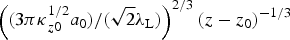
and the magnetic field B = ( k L/ωL) × E . Here, τ is the full-width at half-maximum (FWHM) of laser pulse; w 0 is the focal size; z 0 is the location of focal point; and f is the focal length. As analyzed above, the resonant condition is independent of the magnitude of electric field. Thus, for such a laser pulse, the resonant condition, |Ω| = (e|B 0|/(mωLκ z0)) = 1, is still valid. Figure 5 shows the resonant acceleration of a test electron in a laser field. The length of magnetic field is unlimited. Under this condition, electron can be continuously accelerated for about 100 ps, and get boosted to 4.7 GeV in <3 cm. During the acceleration, although the transverse displacement increases, electron stays in laser field all the time. The diminution of a 0 is the dominant reason that limits energy gain. After passing through the pulse, electron will undergo a standard spiral motion because of the extra field.

Fig. 5. Resonant acceleration of test electron in a focused pulse laser focused at z
0 = 20 μm. a
0 = 10, τ = 15 fs, w
0 = 20 μm,
 $f = ({\rm \pi} w_0^2 /{\rm \lambda} _{\rm L})$
. B
0 = 104 T. Electron initially rests at z = 20 μm.
$f = ({\rm \pi} w_0^2 /{\rm \lambda} _{\rm L})$
. B
0 = 104 T. Electron initially rests at z = 20 μm.
Practically, the magnitude and spatial size of extra magnetic field will be the bottleneck for energy gain. For an electron with an initial energy of 1 MeV, the required magnetic field for resonance is 2.78 kT, which is likely to be realized in the near future. When the length of magnetic field is set to 2 mm, Figure 6 shows the acceleration of an electron. In the combined field, the test electron is resonantly accelerated. After it reaches the edge of extra B-field (pointed by the red arrow in Fig. 6b), the disappearance of extra magnetic field leads to the disappearance of resonant acceleration. The movement of electron later is just an oscillation in the polarization direction of laser combined with a drift in the other two directions. As electron moves far from the focal point and laser axis, the magnitude of field reduces. Finally, the test electron drifts out of laser field, and energy remains unchanged, and its velocity deviates from the laser axis for about 1.52°.

Fig. 6. Resonant acceleration of electron in a focused pulse laser and a limited extra B-field; (a) is the orbit of electron (blue line) and the laser field (the cone). The color represents the normalized laser intensity; (b) is the γ factor of electron.
Under the same conditions, for a plane wave, the final value of γ can be estimated using Eq. (16), which is about 1400. In the case of a focused pulse laser, the eventual energy is some 40% lower. This is a result of comparatively weaker field of the focused laser and spatial limitation of longitudinal B-field.
4. ACCELERATION OF AN ELECTRON BUNCH
So far, we have discussed the resonant acceleration of a test electron; but in laboratory, the source electrons are generated in bunches. Hence, we need to consider the acceleration of the electron bunches. Suppose the initial central energy of a source bunch is 1 MeV, energy spread is 10%, locates around 20 μm initially, and the transverse and longitudinal divergence are 4 and 5 μm, respectively. It is accelerated by the same laser pulse given in Eq. (17). Figure 7 shows the bunch position and energy spectrum at different time. It is clear that under these conditions, a Gaussian electron bunch (Fig. 7a) is completely trapped in the mixed fields, and can be resonantly accelerated to high energy. At about 6.4 ps, the bunch reaches the edge of extra magnetic field. The length of electron bunch is also compressed to the order of laser wavelength. After that, the bunch oscillates in the polarization direction, and drifts forward. Besides, the shape of bunch remains spiral during the whole interacting process, as shown in Figure 7b and 7c.

Fig. 7. Electron distribution and spectrum at (a) and (d) t = 0 ps, (b) and (e) t = 6.5 ps, (c) and (f) t = 75 ps. The color in (a)–(c) represents the γ factor of electron. Unit in (a) and (b) is μm, and mm in (c).
Figure 7d–7f shows the energy spectrum of electron bunch. At first(t = 0), the electrons have a Gaussian distribution (Fig. 7d). During the interaction process, the energy spectrum keeps quasi-monoenergetic. After about 75 ps, the laser has passed through electron bunch. The bunch is accelerated to about 400 MeV. The energy spread is about 7.5%.
By setting a probe electron, which satisfies the resonant condition exactly, we can distinguish the positions and energy (pointed out by the black arrow in Fig. 7) of the resonant electrons in the bunch. During the acceleration, the resonant electrons locate at bunch tail all the time; but their energy is almost the highest. This indicates that resonant electrons can be effectively accelerated. The efficiency of energy transfer from laser to the probe electron is about 7.4 × 10⁻¹².
Besides a good monochromaticity, the electron bunch is also well collimated. Figure 8 shows the distribution of emission angle of electrons after acceleration. Here,
 ${\rm \theta} _{\left\{ {x,y} \right\}} = \arctan (\,p_{\left\{ {x,y} \right\}}/p_z)$
. Though the divergence along the polarization direction is larger than the other, they are both much <3 mrad.
${\rm \theta} _{\left\{ {x,y} \right\}} = \arctan (\,p_{\left\{ {x,y} \right\}}/p_z)$
. Though the divergence along the polarization direction is larger than the other, they are both much <3 mrad.

Fig. 8. Distribution of emission angle in two perpendicular direction.
As the initial energy divergence increases, some electrons may not be trapped. Figure 9 shows the snapshots of bunch position during the acceleration of a Maxwellian electrons with initial temperature of 1 MeV. Figure 9a and 9c shows the moment that the bunch reaches the edge of the extra magnetic field. After that, those electrons that are not resonantly accelerated spread out quickly because of larger divergence in velocity. However, the trapped electrons are resonantly accelerated; they are energetic and have a small divergence, so they move almost straight forward. Considering a deviation of 60% in energy with the probe electron, electrons in this range are considered to be trapped. We pick up these electrons, and present their position as shown in Figure 9c and 9d. They form almost a circle, and keep the shape until the end of the interaction with laser. The gyrate structure in Figure 9d is a clear evidence of resonant acceleration. In the spectrum, the high-energy part is mainly attributed to these trapped electrons.

Fig. 9. Bunch position at different moment. (a) and (c) t = 6.5 ps, (b) and (d) t = 75 ps, (c) and (d) is for the trapped electrons only.
We trace these electrons, and find the initial domain of resonant acceleration. Figure 10a shows the initial spectrum of trapped (blue line) and untrapped (red-dot line) electrons. The trapped electrons amount about 32% of total electron number. They mainly range from 0.75 to 1.41 MeV in energy and from 0.18 to 0.40 in κ z0, corresponding to a deviation of ~33% in energy and ~40% in κ z0 with the proble electron. The other electrons are not trapped and resonantly accelerated to a high-energy state, mainly because of a large deviation in energy and κ z0.

Fig. 10. Initial condition of electron bunch. (a) Spectrum of trapped and untrapped electrons. (b) Spectrum of κ z0. Electrons with energy ranging from 0.75 to 1.41 MeV and κ z0 ranging from 0.18 to 0.40 can be resonantly accelerated.
Figure 11 gives the final spectrum and emission angle distribution of the trapped electrons. They peak around the exact resonant electron energy, and a certain number of electrons are in perfect resonant acceleration condition. FWHM of this peak is 27 MeV, which equals that of the case of a smaller initial energy spread. These electrons also have a very small angular divergence. Shown as in Figure 11b, they all stay between 1° and 2°, and the divergence is about 5.2 mrad, slightly larger than the previous case of a smaller initial energy spread shown in Figure 9; but the electrons are still well collimated.

Fig. 11. Final (a) spectrum and (b) emission angle distribution of the resonant accelerated electrons.
5. CONCLUSION
Using a test electron model, we have obtained the exact resonant function, γ factor, and acceleration gradient of electron in the presence of an axial magnetic field and a linearly or circularly polarized laser with relativistic intensity. Resonance occurs when the cyclotron frequency eB 0/mκ z0 matches ωL, frequency of laser. The matched magnetic field strength decreases with the increasing of initial longitudinal velocity. This helps in reducing the requirements of resonant extra B-field strength.
Theoretically, a perfectly resonant electron can be infinitely accelerated without any dephasing or deceleration if radiation is neglected. The energy gain is proportional to
 $a_0^2 $
and Δϕ2. For a linearly polarized laser, both parallel and anti-parallel B-fields work for resonance. In long term, the mean acceleration gradient is
$a_0^2 $
and Δϕ2. For a linearly polarized laser, both parallel and anti-parallel B-fields work for resonance. In long term, the mean acceleration gradient is
 $\left( {(3{\rm \pi \kappa} _{z0}^{1/2} a_0)/(\sqrt 2 {\rm \lambda} _{\rm L})} \right)^{2/3}(z - z_0)^{ - 1/3}$
; but for circularly polarized lasers, a parallel or anti-parallel one is demanded, the mean acceleration gradient is 21/3 times larger.
$\left( {(3{\rm \pi \kappa} _{z0}^{1/2} a_0)/(\sqrt 2 {\rm \lambda} _{\rm L})} \right)^{2/3}(z - z_0)^{ - 1/3}$
; but for circularly polarized lasers, a parallel or anti-parallel one is demanded, the mean acceleration gradient is 21/3 times larger.
In practice, ultra-intense lasers are strongly focused, and the magnitude and spatial size of extra magnetic field is limited, which is the dominant limitation for energy gain. Using a 2 mm-long, 2.78 kT extra magnetic field, and a strongly focused pulse, an electron with initial energy of 1 MeV can be accelerated to about 400 MeV; and the final velocity deviates from laser axis at a small angle.
Finally, we investigated the LMRA of an electron bunch. Quasi-monoenergetic guassian electrons can produce a quasi-monoenergetic and well-collimated bunch with energy spread about 4.9%, divergence <3 mrad. For electron bunches with wide energy spread, part of the electrons cannot be trapped. They have a large divergence, and spread out quickly after passing through the extra magnetic field. But the trapped electrons are resonantly accelerated. They form a well-collimated monochromatic beam. Considering a typical electron bunch with a charge of ~10 pC, the efficiency will be ~0.1%, which is about the same as that in LWFA (XiaomingWang et al., Reference Xiaomingwang, Zgadzaj, Fazel, Li, Yi, Zhang, Henderson, Chang, Korzekwa, Tsai, Pai, Quevedo, Dyer, Gaul, Martinez, Bernstein, Borger, Spinks, Donovan, Khudik, Shvets, Ditmire and Downer2013; Leemans et al., Reference Leemans, Gonsalves, Mao, Nakamura, Benedetti, Schroeder, Tóth, Daniels, Mittelberger, Bulanov, Vay, Geddes and Esarey2014). Our research shows that LMRA is a good mechanism to accelerate electron beams. This sheds a light on the vacuum table-top laser-driven electron accelerators.
ACKNOWLEDGMENTS
This work is supported by National Key Programme for S&T Research and Development (Grant No. 2016YFA0401100), and China Academy of Engineering Physics Foundation (Grant No. 2014A0102003).


