


1. INTRODUCTION
The progress in laser-plasma accelerators depends substantially on the possibility to provide quasi-monoenergetic acceleration of short electron bunches to high energies (Katsouleas, Reference Katsouleas2004; Leemans & Esarey, Reference Leemans and Esarey2009; Steinke et al., Reference Steinke, van Tilborg, Benedetti, Geddes, Daniels, Swanson, Gonsalves, Nakamura, Shaw, Schroeder, Esarey and Leemans2016). The inhomogeneity of a comparatively short-wavelength laser wake fields tends to increase the energy spread of finite length electron bunches (Andreev et al., Reference Andreev, Kuznetsov and Pogorelsky2000), but at the same time it is responsible for the effects of electron bunching in the energy distribution (Andreev et al., Reference Andreev, Gorbunov and Kuznetsov1996; Reitsma et al., Reference Reitsma, Trines and Goloviznin2000) and in space (Katsouleas et al., Reference Katsouleas, Clayton, Serafini, Pellegrini, Joshi, Dawson and Castellano1996; Andreev & Kuznetsov, Reference Andreev and Kuznetsov2000; Ferrario et al., Reference Ferrario, Katsouleas, Serafini and Zvi2000). The quality of accelerated electron bunches strongly depends on the scheme of the bunch injection and trapping (Andreev & Kuznetsov, Reference Andreev and Kuznetsov2003; Kuznetsov, Reference Kuznetsov2016a , Reference Kuznetsov b ; Pugacheva & Andreev, Reference Pugacheva and Andreev2016).
One of the limits of plasma-based accelerators is due to the field driven by the accelerated electron bunch itself (Katsouleas et al., Reference Katsouleas, Wilks, Chen, Dawson and Su1987; Akopyan et al., Reference Akopyan, Matevosyan, Gevorkyan and Oganesyan2002; Nersisyan & Matevosyan, Reference Nersisyan and Matevosyan2010). This beam loading effect limits the charge that can be accelerated since the longitudinal field generated by the bunch can cancel out the accelerating laser wakefield for the trailing electrons of the bunch. Beam loading leads to the decrease of the beam energy and the increase of the energy spread for large beam charge (Rechatin et al., Reference Rechatin, Davoine, Lifschitz, Ismail, Lim, Lefebvre, Faure and Malka2009). For the specially managed bunch charge and shape, the superposition of the laser wakefield and the plasma wave driven by the leading electrons of the bunch can be made constant over the bunch length, which minimizes the energy spread (Katsouleas et al., Reference Katsouleas, Wilks, Chen, Dawson and Su1987; Andreev & Kuznetsov, Reference Andreev and Kuznetsov2008; Tzoufras et al., Reference Tzoufras, Lu, Tsung, Huang, Mori, Katsouleas, Vieira, Fonseca and Silva2008). Beam loading plays also an important role in a beam–plasma section matching strategy for the laser-plasma wakefield accelerator where the injected electron beam is produced by an external source (Rossi et al., Reference Rossi, Anania, Bacci, Belleveglia, Bisesto, Chiadroni, Cianchi, Curcio, Gallo, Giovenale, Pirro, Ferrario, Marocchino, Massimo, Mostacci, Petrarca, Pompili, Serafini, Tomassini, Vaccarezza and Villa2016; Tomassini & Rossi, Reference Tomassini and Rossi2016), and especially for the many-stage acceleration.
In this paper, trapping and acceleration of short electron bunches externally injected into the wakefields generated by intense femtosecond laser pulse in plasma channel are studied. In contrast to the last two papers (Rossi et al., Reference Rossi, Anania, Bacci, Belleveglia, Bisesto, Chiadroni, Cianchi, Curcio, Gallo, Giovenale, Pirro, Ferrario, Marocchino, Massimo, Mostacci, Petrarca, Pompili, Serafini, Tomassini, Vaccarezza and Villa2016; Tomassini & Rossi, Reference Tomassini and Rossi2016), where the energy of the injected bunch was near resonant energy for the phase velocity of the wake field and the acceleration length was limited to 4 cm that restricted obtained energy gain to 300 MeV, we have investigated injection of low-energy bunches, which allows us to obtain a substantial longitudinal bunch compression (Andreev & Kuznetsov, Reference Andreev and Kuznetsov2000, Reference Andreev and Kuznetsov2003; Grebenyuk et al., Reference Grebenyuk, Mehrling, Tsung, Floettman and Osterhoff2012), and also obtain the bunch energy gain to GeV range with a small energy spread on the acceleration length of 10–20 cm. The influence of the laser non-linear dynamics (Andreev et al., Reference Andreev, Baranov, Cros, Fortov, Kuznetsov, Maynard and Mora2011a , Reference Andreev, Baranov, Cros, Maynard, Mora and Veysman2013) and beam loading to the final energy and energy spread of the accelerated electrons (Andreev & Kuznetsov, Reference Andreev and Kuznetsov2008; Rechatin et al., Reference Rechatin, Davoine, Lifschitz, Ismail, Lim, Lefebvre, Faure and Malka2009; Andreev et al., Reference Andreev, Kuznetsov, Cros, Fortov, Maynard and Mora2011b ) is investigated.
The paper is organized as follows. In the next section, the modeling parameters and the wakefield generation in the moderate non-linear regime are described. After this, trapping and acceleration of electron bunches of different charge investigated starting with the approximation of test particles. In the last section, restrictions on the charge of a bunch due to the beam loading effect are analyzed for obtaining a small energy spread in an accelerated electron bunch.
2. MODELING PARAMETERS AND WAKEFIELD GENERATION
The 100-terawatt femtosecond laser pulse propagating in a preformed plasma channel was used for trapping and acceleration of externally injected electron bunches in the laser generated wakefields. Initially, at the entrance of the plasma channel, the laser pulse envelope was Gaussian in both longitudinal and transverse directions with laser wavelength λ0 = 0.8 μm, dimensionless amplitude a
0 = 0.964 and full width at half maximum (FWHM) pulse duration
 ${\rm \tau} _{{\rm FWHM}} = \sqrt {2{\rm ln}2} \,{\rm \tau} _{\rm L} = 50\,{\rm fs}$
.
${\rm \tau} _{{\rm FWHM}} = \sqrt {2{\rm ln}2} \,{\rm \tau} _{\rm L} = 50\,{\rm fs}$
.
The laser pulse with waist radius r
0 = 68.2 μm was focused onto the entrance of plasma channel with parabolic in the radial direction density profile
 $n_0(r) = N_0[1 + r^2/R_{{\rm ch}}^2 ]$
and electron plasma density on the axis N
0 = 1.75 × 1017 cm−3. To prevent laser pulse spreading, the channel radius was matched with the laser spot size by the linear condition
$n_0(r) = N_0[1 + r^2/R_{{\rm ch}}^2 ]$
and electron plasma density on the axis N
0 = 1.75 × 1017 cm−3. To prevent laser pulse spreading, the channel radius was matched with the laser spot size by the linear condition
 $R_{{\rm ch}} = k_{\rm p}r_0^2 /2$
(Sprangle et al., Reference Sprangle, Esarey, Krall and Joyce1992; Andreev et al., Reference Andreev, Kirsanov and Gorbunov1995), where k
p = ωp/c,
$R_{{\rm ch}} = k_{\rm p}r_0^2 /2$
(Sprangle et al., Reference Sprangle, Esarey, Krall and Joyce1992; Andreev et al., Reference Andreev, Kirsanov and Gorbunov1995), where k
p = ωp/c,
 ${\rm \omega} _{\rm p} = \sqrt {4{\rm \pi} N_0e^2/m_{\rm e}} $
is the electron plasma frequency, c is the speed of light, and e, m are the electron charge and mass, respectively. For the chosen plasma density, wakefield γ-factor determined by the phase velocity of excited plasma wave equals to
${\rm \omega} _{\rm p} = \sqrt {4{\rm \pi} N_0e^2/m_{\rm e}} $
is the electron plasma frequency, c is the speed of light, and e, m are the electron charge and mass, respectively. For the chosen plasma density, wakefield γ-factor determined by the phase velocity of excited plasma wave equals to
 ${\rm \gamma} _{{\rm ph}} \cong {\rm \omega} _0/{\rm \omega} _{\rm p} \equiv \sqrt {n_{{\rm cr}}/N_0} = 100$
(where ω0 is the laser frequency and n
cr is the critical electron density), dimensionless laser parameters correspond to ωpτL = 1.0, k
p
r
0 = 5.355 that gives k
p
R
ch = 14.34 (R
ch = 180 μm). The laser pulse power, P
L = 145 TW, does not exceed critical one for relativistic self-focusing, P
L/P
cr = 0.854.
${\rm \gamma} _{{\rm ph}} \cong {\rm \omega} _0/{\rm \omega} _{\rm p} \equiv \sqrt {n_{{\rm cr}}/N_0} = 100$
(where ω0 is the laser frequency and n
cr is the critical electron density), dimensionless laser parameters correspond to ωpτL = 1.0, k
p
r
0 = 5.355 that gives k
p
R
ch = 14.34 (R
ch = 180 μm). The laser pulse power, P
L = 145 TW, does not exceed critical one for relativistic self-focusing, P
L/P
cr = 0.854.
In order to compensate partially the relativistic and ponderomotive non-linearities and prevent ponderomotive self-focusing and filamentation (Andreev & Kuznetsov, Reference Andreev and Kuznetsov2003; Andreev et al., Reference Andreev, Gorbunov, Mora and Ramazashvili2007; Gaur et al., Reference Gaur, Rawat and Purohit2016; Sharma et al., Reference Sharma, Kumar, Hussain and Sharma2017) the length of the laser pulse was chosen two times shorter than the length for resonant excitation of the wakefield. Under these conditions, at the cylindrical symmetry of focusing the laser pulse into the plasma channel (Veysman & Andreev, Reference Veysman and Andreev2016), the laser can propagate over many Rayleigh length without substantial distortions and generate stable wakefields in a moderately non-linear regime. The wakefields structure was modeled using LAPLAC code (Andreev & Kuznetsov, Reference Andreev and Kuznetsov2008) taking into account the non-linear laser and wakefield dynamics.
Figure 1a, b demonstrate the longitudinal structure of the wakefield generated at the channel entrance (z = 0) and at the laser propagation distance z = 0.51 cm. Here and below, the dimensionless variables and functions are used: ξ = k p(z − ct), ρ = k p r, the laser envelope a = |eE L/mω0 c| and the normalized wakefield potential ϕ = eΦ/mc 2.
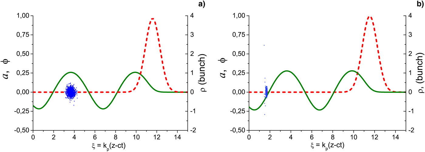
Figure 1. The laser pulse normalized envelope a max(ρ = 0, ξ) (dashed red line) and wakefield potential ϕ(ρ = 0, ξ) (solid olive line) on the axis at the channel entrance z = 0 (a) and at the laser propagation distance z = 0.51 cm (where the bunch is trapped) (b). Blue points indicate the bunch particles on the plane (ξ, ρ). The laser and plasma parameters are given in the text.
Electron bunch of a few thousands particles (distributed randomly with Gaussian envelope) was externally injected into the second maximum of wakefield potential (to avoid overlapping with laser pulse) at the phase ξinj = 3.67 and is shown in Figure 1a as blue points. Longitudinal dispersion of the bunch equals σ z,inj = 2.3 μm [that corresponds to FWHM bunch duration ≅ 23 fs, k pσ z,inj = 0.18 and dimensionless root mean square (RMS) bunch length k p L b0 ≅ 0.41]. The radial bunch dispersion was σr,inj = 1.88 μm (k pσr,inj = 0.148, k p R rms = 0.214). Injected bunch was monoenergetic with initial energy of electrons E inj = 1.9mc 2 and normalized emittance εN = 0.346 mm × mrad, which corresponds to the matched bunch radius k p R rms ≈ 0.2 if estimated by the radial wakefield force averaged over the acceleration length ≈20 cm.
3. TRAPPING AND ACCELERATION OF ELECTRONS
3.1. Test particles approximation
We start with an electron bunch of test particles, that is, neglecting the loading effect describing self-action of the bunch charge. The restrictions on the charge of bunch from this approximation will be discussed in the next subsection.
The final characteristics of accelerated electrons (first of all, the bunch energy spread) strongly depend on the length of trapped bunch (Andreev et al., Reference Andreev, Kuznetsov and Pogorelsky2000; Andreev & Kuznetsov, Reference Andreev and Kuznetsov2003). A substantial longitudinal bunch compression can be achieved in the process of bunch trapping into the wakefield, if the bunch is injected in the region of the wakefield potential maximum with an energy less than the resonant one, E inj < E res = mc 2γph (Andreev & Kuznetsov, Reference Andreev and Kuznetsov2000). On the assumption of the constant laser pulse and generated wakefield, the energy conservation law determines the difference of the wakefield potential in order that electrons with the initial energy E inj [injected in a vicinity of the potential maximum ϕmax ≡ ϕ(ξm) = ϕ(ξinj)] were trapped (i.e., have obtained the resonant energy E res) at the given phase ξtr:
 $${\rm \phi} _{{\rm max}} - {\rm \phi} ({\rm \xi} _{{\rm tr}}) = E_{{\rm inj}}/mc^2 - \left[ {(1 - {\rm \gamma} _{{\rm ph}}^2 )(E_{{\rm inj}}^2 /m^2c^4 - 1)} \right]^{1/2}.$$
Note that this condition was obtained in one-dimensional approximation, and for stable compression of an electron bunch (in view of its radial motion), the trapping phase should be chosen so that all area of electron motion in the longitudinal direction ξ ∈ [ξtr, ξ
m] is in the focusing phase of the wakefield. The indicated above laser and plasma parameters for the specified bunch injected along the channel axis OZ satisfy these conditions and the bunch is trapped at the laser propagation distance
 $z \cong 0.51{\kern 1pt} \,{\rm cm}$
and trapping phase ξtr ≅ 1.7 in the vicinity of the focusing phase boundary (see Fig. 1b). The compressed length of the trapped bunch can be estimated through the wakefield potential at the phases of injection and trapping:
$z \cong 0.51{\kern 1pt} \,{\rm cm}$
and trapping phase ξtr ≅ 1.7 in the vicinity of the focusing phase boundary (see Fig. 1b). The compressed length of the trapped bunch can be estimated through the wakefield potential at the phases of injection and trapping:
 $$L_{\rm b} = \displaystyle{1 \over 2}k_{\rm p}L_{{\rm b}0}^2 \displaystyle{{\left \vert {\partial ^2{\rm \phi} ({\rm \xi} _{\rm m})/\partial {\rm \xi} ^2} \right \vert} \over {\partial {\rm \phi} ({\rm \xi} _{{\rm tr}})/\partial {\rm \xi}}}. $$
From this expression for the weakly non-linear wakefield (neglecting deviations from the harmonic shape of the potential) the maximum compression takes place when the bunch is trapped at the vicinity of maximum of the accelerating force F
z = ∂ϕ/∂ξ and gives the length of trapped bunch
 $L_{\rm b} = 1/2k_{\rm p}L_{{\rm b}0}^2 $
that for discussed parameters corresponds to k
p
L
b ≅ 0.08. This value is close to the RMS bunch length k
p
L
rms ≅ 0.07 obtained in the simulations after bunch trapping with allowance for the non-linear laser and wakefield dynamics as shown in Figure 2 by dotted line. In course of trapping and acceleration, the bunch is shrunk also in radius (see Fig. 2, solid line) that helps to prevent substantial growth of the bunch emittance in the non-stationary accelerating and focusing fields, as shown in Figure 2 by the line marked by squares.
$L_{\rm b} = 1/2k_{\rm p}L_{{\rm b}0}^2 $
that for discussed parameters corresponds to k
p
L
b ≅ 0.08. This value is close to the RMS bunch length k
p
L
rms ≅ 0.07 obtained in the simulations after bunch trapping with allowance for the non-linear laser and wakefield dynamics as shown in Figure 2 by dotted line. In course of trapping and acceleration, the bunch is shrunk also in radius (see Fig. 2, solid line) that helps to prevent substantial growth of the bunch emittance in the non-stationary accelerating and focusing fields, as shown in Figure 2 by the line marked by squares.
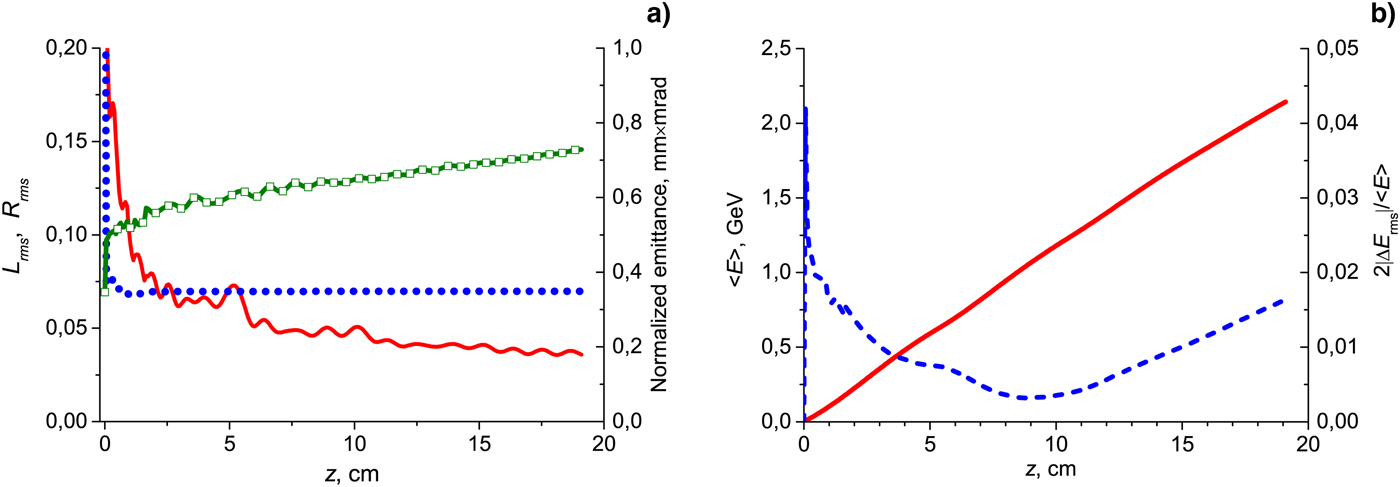
Figure 2. The normalized by k p RMS bunch length (dotted line, left axis) and RMS bunch radius (solid line, left axis) and normalized emittance (line marked by squares, right axis) as functions of the acceleration length (a). The averaged energy (solid line) and the normalized RMS energy spread (dashed line) of the accelerated electron bunch as functions of the acceleration length (b).
The small longitudinal and transverse sizes of the trapped electrons provide effective acceleration of the bunch to high energies with small energy spread (see Fig. 2). The clearly seen minimum of the energy spread at the length of acceleration z ≅ 9 cm is a result of the energy chirp obtained by the bunch in the process of trapping and subsequent acceleration in the non-uniform wakefields that leads to the effect of bunching in the energy space (Kuznetsov, Reference Kuznetsov2012a , Reference Kuznetsov b ).
3.2. Restrictions on the bunch charge from loading effect
Self-action of the bunch charge (beam loading effect) can lead to substantial modification of the wakefield generated by laser pulse and so can influence to the final energy of accelerated electrons and especially to the energy spread of electron bunch. It is known (Katsouleas et al., Reference Katsouleas, Wilks, Chen, Dawson and Su1987; Andreev & Kuznetsov, Reference Andreev and Kuznetsov2008; Rechatin et al., Reference Rechatin, Davoine, Lifschitz, Ismail, Lim, Lefebvre, Faure and Malka2009) that a moderate charge of the bunch can provide more homogeneous accelerating force and so leads to decrease of the energy spread, but increase of the bunch charge leads to the degradation of monoenergetic acceleration.
Figure 3 shows dependencies of the electron bunch energy spread on the distance of acceleration for different charges of the bunch (test particles – Q b = 0, Q b = 1 and 2 pC). The minimum RMS energy spread of 0.16%, normalized to the averaged energy of an electron in the bunch, is obtained for the charge of electron bunch Q b = 1 pC, while for the test particles (without loading effect, Q b = 0), the spread is two times higher. A further increase in the charge of the bunch to Q b = 2 pC leads to a significant increase in the energy spread to 0.78%, but still remains at <1%. It should be noted that for the parameters discussed, at a given acceleration length, the average energy of the accelerated bunch is practically independent of the charge of the bunch, so that the bunch energy increases with the acceleration length, as shown in the Figure 2b. At the same time, the beam loading effect significantly affects the capture of the beam and increases the acceleration length, and therefore the bunch energy, for which the width of energy distribution in the bunch is minimal (see Figs 2b and 3).

Figure 3. The dependencies of the electron bunch energy spread on the distance of acceleration for different charges of the bunch: test particles – Q b = 0 (dash blue line), Q b = 1 pC (solid magenta line), and Q b = 2 pC (dash dot brown line).
In conclusion, the effect of laser non-linear dynamics and the beam loading effect (self-action of the beam charge) on the finite energy and energy spread of accelerated electrons were investigated. Due to the special control of the laser and plasma parameters for a partial compensation of relativistic and ponderomotive non-linearities, the non-linear dynamics of the laser pulse does not have a significant effect on the capture and compression of the injected electron bunch, which allows to use analytical estimates of the compressed bunch parameters. It is found that, for discussed parameters, the charge of the bunch Q b ≅ 1 pC minimizes the energy spread, which decreases two times in comparison with the case of negligibly small bunch charge (test particles approximation). With increase of the charge of the bunch, beam loading effect increases the energy spread, but at the same time increases the finite energy of accelerated electrons at a minimal energy spread.
A more detailed analysis and parameter optimization of trapping and acceleration of externally injected electrons in the moderately non-linear wakefield generated by the laser pulse in a plasma channel, as well as a beam–plasma section matching for the many-stage acceleration will be the subject of further investigations.
ACKNOWLEDGMENTS
This work was supported by the RA MES State Committee of Science, in the frames of the research project 15T-1C231 and was partly supported by the Presidium of RAS program on the fundamental research.


