


Introduction
With the rapid development of wireless technology, RF/microwave circuit and system is becoming a more complicated space, so there are strong electromagnetic mutual interferences between the radio devices, especially in Ultra-Short wave band. The fully tunable filters with tunable operating frequency and bandwidth can efficiently improve the reception of the useful signals and rejection of the interference signals in Ultra-Short wave band.
Significant efforts have gone into designing the fully tunable filters. Generally, the fully tunable filters can be designed by adopting the resonators with special structures. The multiple mode resonators (MMRs) are a widely used method of fully tunable filter with widely tunable range [Reference Mao, Che, Choi, Tam and Xue1–Reference Lu, Tang, Barker, Li and Yan8], especially the transmission line resonators [Reference Mao, Che, Choi, Tam and Xue1–Reference Dakotah and Dimitra4, Reference Roberto, Dimitra and Dimitrios6–Reference Lu, Tang, Barker, Li and Yan8] or rectangular ring resonators [Reference Wang, Zhou, Zhang and Han5]. This method has the advantages of compact size and low cost. However, it is very difficult to combine resonators with more orders to improve Out-of-band suppression performance. Another classical method to realize the fully tunable filters is by inserting tunable devices into the traditional coupling structures [Reference Adhikari, Ghiotto and Wu9–Reference Akash and Liu13], which can achieve a more steeply Out-of-band suppression. These fully tunable filters employ a wide variety of resonators, including cavity tunable resonators [Reference Lu, Tang, Barker, Li and Yan8, Reference Adhikari, Ghiotto and Wu9]. However, the design complexity and size of the fully tunable filter is increased. So overall, developing a high-performance fully tunable filter with compact size and simple design method may be a challenging task.
This letter proposed a novel tunable coupling structure and its applications in a fully tunable filter. The tunable coupling structure mainly consists of a rectangular open ring and tunable devices, which has the characteristics of tunable performance and simple design method. Moreover, the coupling structure proposed can be easily cascaded to achieve more steeply out-of-band rejection performance.
The input/output coupling and inter-cavities coupling can all be realized by the tunable coupling structure. The design procedure of the fully tunable filters adopting the tunable coupling structures is similar to the traditional ones [Reference Bahram, Yu and Brian10, Reference Himanshu, Sigmarsson, Moon, Peroulis and Chappel11].
Design of tunable cavity
The structure of the microstrip tunable cavity adopted in this letter is shown in Fig. 1, which determine the operating frequency and tuning range.

Fig. 1. The structure of the tunable resonant cavity.
The tunable cavity shown in Fig. 1 mainly consists of inner microstrip conductor, metallized wall, metallized holes, and tunable capacitors Cf. The parameters of the structure in Fig. 1 are chosen as follows (unit: mm): l = 77, h = 73, w = 10, D = 3. The width of the microstrip line of the rectangular ring is 1 mm. The microstrip width of the metallized wall is 2 mm. The diameter of the metallized holes in the metallized wall is 1 mm.
The resonant performance of the tunable cavity is shown in Fig. 2. Through adjusting the tunable capacitor Cf in the range of 1pf-7pf, the resonant frequency of the tunable cavity can be tuned in the range of 390–539 MHz.

Fig. 2. The resonant frequency of the tunable resonant cavity.
Design of the tunable coupling structure
The geometry of the tunable coupling structure using in the inter-cavities coupling is shown in Fig. 3. The tunable coupling structure mainly consists of an open rectangular ring and a tunable capacitor Cc, which is located between two resonant cavities and across through a window in the middle metalized wall. The tunable capacitor Cc is placed at the top of the rectangular ring and grounded to the outer wall formed by metalized holes and microstrip lines. In Fig. 3, the resonant frequency of the two tunable cavities is mainly determined by Cf, and the inter-cavities coupling coefficients are mainly determined by Cc. The coupling coefficients can also be tuned by Cs (the slot between the inner microstrip conductor and tunable coupling structure) and Ch, similar to the traditional coupling structure.

Fig. 3. The geometry of the tunable coupling structure.
The inter-cavities coupling coefficients performance of the tunable coupling structure are shown in Fig. 4.

Fig. 4. The coupling coefficients performance of the tunable coupling structure.
It is assumed that in Fig. 4 the resonant frequency of the tunable cavity is fixed at 460 MHz. The size parameters of the inter-cavities coupling structure are chosen as follows (unit: mm): l = 77, h = 74, w = 10, D = 3, slot = 10, ch = 30, ch1 = 25.
It is can be seen from Fig. 4 that the coupling coefficients increase as the tunable capacitor Cc increases. When Cc is varying from 1pf to 7pf and Cs is selected in the range of 0.3–0.5 mm, the coupling coefficients between resonators can be tuned in the range of 0.012–0.026. It has a little influence to the resonant frequency by Cc, which can be corrected through fine tuning of Cf.
The structure of input/output coupling is shown in Fig. 5.

Fig. 5. The structure of input/output coupling.
The resonant frequency of the tunable cavity is also fixed in 460 MHz. The size parameters of the input/output coupling structure are chosen as follows (unit: mm): fh = 40, fh1 = 35, l = 77, w = 10.
The input/output Q value performance is shown in Fig. 6.

Fig. 6. The input/output Q value performance.
As can be observed, when fedc is changing from 1pf to 7pf and feds is selected in the range of 0.3–0.5 mm, the loaded Q value is decreased from 77 to 20. The change of fedc has a little influence on the resonant frequency, but with a little adjustment for Cf, the influence can be corrected.
Design of fully tunable filter
Based on the above parameter study of the tunable coupling structures, a fully tunable filter can be constructed. The design procedure can be divided into three stages.
Firstly, the parameters of the tunable cavity and the tunable devices should be determined according to the required operating range of the fully tunable filter. The center frequency of the tuning range is mainly determined by the size of tunable cavity. The tuning range is mainly determined by the tunable capacitors. The tuning range must be designed with some redundancy to eliminate the changes of the tuning range due to the insertion of a tunable coupling structure.
Secondly, the tunable coupling structure and tunable feed structure should be designed according to the bandwidth range of the fully tunable filter. The average bandwidth is mainly determined by the size parameters, positions of rectangular open ring, and tunable capacitor. The tuning range is mainly determined by the tunable capacitor.
Thirdly, some fine adjustments of the dimensions of tunable cavity and rectangular open rings are required to meet all design specifications of the fully tunable filter.
To verify the suitability of the tunable coupling structure proposed in this paper, a fully tunable bandpass filter with five cavities operating in the range of 400–530 MHz is proposed in this letter. The 3-dB bandwidth of the fully tunable filter can be tuned in 8–14 MHz.
According to the specifics mentioned above, the resonant frequency of the tunable cavity should be tuned in the range of 400–530 MHz. According to the characteristic analyze of tunable cavity above, the size parameters are selected as follows (unit: mm): l = 77, h = 74, w = 10, D = 3.
To meet the requirement of the bandwidth tuning range, the coupling coefficients in 400 MHz should be tuned in a range of 0.0173–0.03028(M12), and 0.01271–0.02225(M23). The coupling coefficients in 530 MHz should be tuned in a range of 0.0385–0.02423(M12) and 0.01017–0.0178(M23). According to the characteristic analyze of tunable coupling structure above, the size parameters are selected as follows (unit: mm): s1 = 0.37, s2 = 0.43, slot = 10, ch = 30, ch1 = 35.
To meet the requirement of the bandwidth tuning range, the loaded Q value should be tuned in a range of 27.81–48.66(@400 MHz) and 34.76–60.83(@530 MHz). According to the characteristic analyze of tunable coupling structure above, the size parameters of the feed structure are selected as follows (unit: mm): feds = 0.4, fh = 40, fh1 = 35, fedw = 1.7.
The fully tunable bandpass filter is designed, fabricated, and measured.
The designed layout of the fully tunable filter is shown in Fig. 7.

Fig. 7. The designed layout of the fully tunable filter.
The design parameters of this fully tunable filter were summarized in Table 1.
Table 1. The design parameters of this fully tunable filter (Unit: mm)

The size marks of the fully tunable filter are the same as Figs 1, 3, and 5. The substrate of the tunable filter is Rogers 4350B, with dielectric constant of 3.66 and thickness of 0.762 mm. The tunable device (Cf, Cc1, and Cc2) is Ma46H202 provided by MACOM Technology. The fabricated fully tunable filter is shown in Fig. 8.

Fig. 8. The fabricated fully tunable filter.
The simulation and measurement are carried out using the HFSS and the RS ZVB4 network analyzer, respectively. Simulated and measured frequency responses are shown in Figs 9–12.

Fig. 9. Simulated and measured frequency responses of the fully tunable filter (400 MHz).

Fig. 10. Simulated and measured frequency responses of the fully tunable filter (460 MHz).
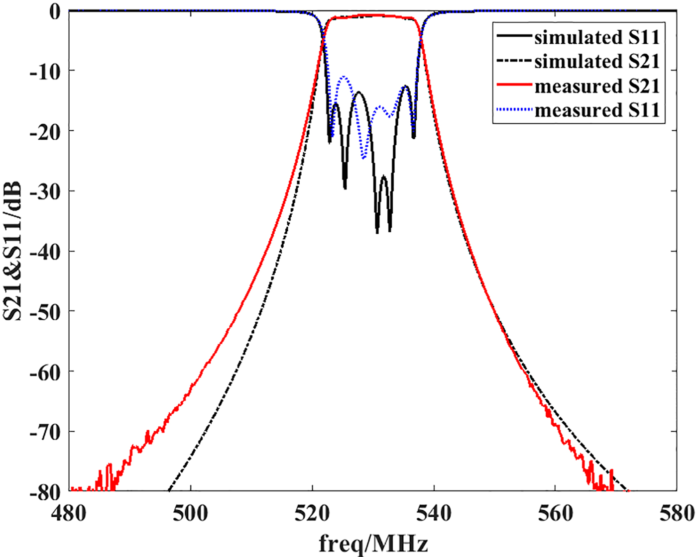
Fig. 11. Simulated and measured frequency responses of the fully tunable filter (530 MHz).

Fig. 12. Tuned bandwidth in 460 MHz.
The bias voltage of the varactors Cf1,Cf2, and Cf3 is 5.2 V. The bias voltage of the varactors Cc1,Cc2, and fedc is 5.2 V in Fig. 9.
The bias voltage of the varactors Cf1,Cf2, and Cf3 is 10.3 V. The bias voltage of the varactors Cc1,Cc2, and fedc is 5.2 V in Fig. 10.
The bias voltage of the varactors Cf1,Cf2, and Cf3 is 5.2 V. The bias voltage of the varactors Cc1,Cc2, and fedc is 20 V in Fig. 11.
The bias voltage of the varactors Cf1,Cf2, and Cf3 is 5.2 V. The bias voltage of the varactors Cc1,Cc2, and fedc is 5.2 V(14 MHz), 10.3 V(10 MHz), and 20 V(8 MHz), respectively.
In order to achieve low insertion loss of the fully tunable filter, the value of Cf , Cc, and fedc are selected in the range of 0.7pf- 4pf, and then the unloaded Q-value of the tunable cavities is more than 500. A large capacitance range can be realized through several paralleled varactor diodes. From Figs 9–11, the tuning range of the pass band is from 400 to 530 MHz. From Fig. 12, the bandwidth of the pass band can be tuned in the range of 8–14 MHz. The measured results are in good agreement with the simulated ones. For the loss of the varactors and the substrates, the measured insertion loss is a little worse than the simulated ones.
The comparison between the proposed fully tunable bandpass filter and the ones proposed in the references is presented in Table 2.
Table 2. Comparison between the proposed tunable BPF and the references

Conclusion
This letter proposed a fully tunable bandpass filter adopting a novel tunable coupling structure. The tunable cavity and tunable coupling structure can be combined to achieve better Out-of-band suppression performance. The design method of the fully tunable filter adopting the tunable coupling structure is similar to the typical frequency-fixed bandpass filter. The tunable coupling structure can be used in other frequencies.
Author ORCIDs
Zhonghai Zhang, 0000-0001-8076-3347
Acknowledgement
This work was supported by The National Natural Science Fund (No.61501153).
 Zhong-Hai ZHANG was born in the Inner Mongolia Autonomous Region of China. He received his BS, MS, and Ph.D. degree major of electromagnetic field and microwave technology from Xidian University in 2001, 2004, and 2012, respectively. His research interests include antenna propagation and microwave circuits.
 Fei ZHAO was born in the Sichuan province of China. He received the B.S. degree in information engineering from Beijing Institute of Technology, Beijing, China, in 2005, and received the M.S. and Ph.D. degrees in electromagnetic and microwave technology from National University of Defense Technology, Changsha, China, in 2007 and 2012, respectively. From 2013, he is working at Science and Technology on Blind Signal Processing Laboratory of Southwest Electronics and Telecommunication Technology Research Institute, Chengdu, China. His research interests include theory of conformal arrays, technology of microwave system and circuit, and wideband antennas.
 Aiting WU was born in Pujiang, Zhejiang, China. She received her BS and MS degree in electronic engineering from Hangzhou Dianzi University, Hangzhou, China, in 2002 and 2005, respectively, and her Ph.D. degree in electromagnetic field and microwave technology from Xidian University, Xi'an, China, in 2015. She is currently an associate professor in the School of Electronic information at Hangzhou Dianzi University. Her research interests include antenna design, RF circuits, and microwave communicate.


