


1. Introduction
Since the 1970s, the electric wheelchair has become an indispensable technical mobility aid for people with severe motor deficiencies that do not allow to drive a manual wheelchair. However, a significant number of potential users of powered wheelchairs have difficulty or are unable to control them due to severe motor, cognitive or sensory impairments [Reference Fehr, Langbein and Skaar1, Reference Simpson, LoPresti and Cooper2]. The first studies on the “smart wheelchairs” (SW: instrumented wheelchairs able to achieve autonomous or semi-autonomous motions) aimed at compensating this problem date back to the end of the 1980s [Reference Madarasz, Heiny, Cromp and Mazur3–Reference Nisbet6]. Since then a large number of projects have emerged from the laboratories [Reference Leaman and La7, Reference Simpson8]. One of the first objectives of the researchers was the design of an autonomous control mode [Reference Madarasz, Heiny, Cromp and Mazur3]. However, at the time, the technologies were not mature enough to ensure acceptable reliability of the prototypes. Nowadays, even though significant progress has been made in this field, full automation is only possible in a predictable environment where the consequences of an error are acceptable [Reference Abbink9]. These conditions are not met in the context of SW. On the other hand, several studies have underlined the need to make the best use of the motor and cognitive capacities of the person for psychological reasons (to remain in control of the system) and for maintaining these capacities [Reference Nisbet10, Reference Rushton11]. The specificity of the problem thus lies in the importance of optimal cooperation between the user, a person with disability, and the machine, an instrumented powered wheelchair. This interaction is to be studied under two aspects: the distribution of tasks between human and machine and the dialogue to be established between the two entities. On the latter point, it is particularly essential that the person clearly understands the actions of the machine both for questions of confidence in the robot and to be able to react reliably.
As the potential SW user is a person with severe motor disability, the choice of the human–machine interface (HMI), more specifically of the interaction sensor, is crucial to enable him/her to interact with the robot. This sensor is in most cases a joystick or a functional equivalent (controlled with chin, head, foot, etc.). If the person cannot reliably control a mechanical HMI because of a lack of force or precision in the gestures, more sophisticated sensors can be used to make the best use of its residual motor capacities, such as electromyographical sensors placed on the face [Reference Tamura, Manabe, Goto, Yamashita and Tanno12] or an eye-tracking system [Reference Eid, Giakoumidis and El Saddik13] for example. If the person does not have a reliable physiological site, a brain–computer interface may be a possible recourse [Reference Tang, Liu, Hu and Zhou14].
As far as human–machine cooperation is concerned, the research problems encountered in the field of SW present many analogies with those of teleoperation robotics with the essential difference that the operator is located on the mobile robot and therefore has direct visual and haptic feedback of the task being performed. The distance between the operator and the machine is not physical but results from the motor, possibly cognitive or sensory impairments of the person. Because of these disabilities, some of the navigation tasks are delegated to the robot, whether at the operational level (e.g., obstacle avoidance), tactical level (e.g., crossing a narrow doorway) or strategic level (e.g., assistance in locating and path planning for people with cognitive or visual disorders).
Various taxonomies of cooperative controls have been described in the literature [Reference Flemisch, Abbink and Itoh15]. Thus in [Reference Bourhis and Agostini16], the possible modes of cooperation between the SW and its driver are listed based on Rasmussen’s three-level model of behaviour, behaviours based on knowledge, rules or skill [Reference Rasmussen17], for human and, by extension, for machine. More generally and more recently in ref. [Reference Abbink9], a hierarchical framework is presented to describe the cooperative control of a process or vehicle by vertically decomposing into four levels of tasks, executive, operational, tactical and strategic. At each level, human and machine interact at Rasmussen’s three levels of behaviour. This framework underlines the importance of communication between the two cooperating entities. These taxonomies are based on a distinction proposed by ref. [Reference Sheridan18] to describe the distribution of tasks between a human operator and a remotely operated robot from a fully manual to an automatic mode. It introduces the notions of “shared control” where human and machine work together on the same task that they would both be able to perform alone, and “traded control” where the two entities successively take control. These two modes of control can coexist in the same system [Reference Flemisch, Abbink and Itoh15]. In ref. [Reference Bourhis and Agostini16], a variant of traded control is mentioned, the “combined control” in which the human can intervene punctually in an automatic movement or the SW in a manual movement.
The SW shared control mode can be considered in two ways, by mixing the commands from both entities, human and machine or by transmitting information to the pilot via haptic feedback. Thus in ref. [Reference Hadj-Abdelkader, Bourhis and Cherki19], a haptic information depending on the distance to the obstacles around the chair is sent back to the pilot using a force feedback joystick. Two types of algorithms are proposed: “passive” force feedback (the joystick resists movement towards an obstacle) and “active” force feedback (the joystick moves the wheelchair away from obstacles). The method described in ref. [Reference Devigne, Pasteau, Babel, Narayanan, Guegan and Gallien20] does not require local mapping: force feedback is calculated in the speed range where authorised and prohibited zones are defined.
In the second type of shared control, the human and the robot each simultaneously control a part of the driving task: the person indicates the direction to follow and the robot takes care of locally avoiding obstacles. The first algorithm based on this principle, the vector field histogram method, was developed using data from ultrasonic rangefinders [Reference Borenstein and Koren21]. A polar histogram representing the space around the wheelchair is constructed and the free direction closest to that indicated by the joystick is chosen as the direction of advance at each moment. The user’s intention can also be predicted with the help of a map of the environment in which goals are defined [Reference Carlson and Demiris22]–[Reference Maciel and Pinto24]. The authors in ref. [Reference Urdiales, Fernandez-Espejo, Annicchiaricco, Sandoval, Caltagirone and Syst25] proposes to modulate the weights of the user and of the robot in the control, based on physiological signals indicating the stress of the person.
In the traded mode, the navigation task changes from manual control of the wheelchair to automatic control during the navigation task. This is done in the form of a call to an automatic primitive such as doorway crossing [Reference Burhanpurkar, Labbé, Guan, Michaud and Kelly26, Reference Pasteau, Narayanan, Babel and Chaumette27], wall following [Reference Lee, Chiu and Kuo28, Reference Panzarella, Schwesinger, Spletzer, Wettergreen and Barfoot29], person following [Reference Leigh, Pineau, Olmedo and Zhang30] or automatic navigation to a target point [Reference Iturrate, Antelis, Kubler and Minguez31]. In most applications reported in the literature, it is the person who decides to change mode. Thus in ref. [Reference Leishman, Horn and Bourhis32], the authors propose a “deictic” interface: a correspondence established between data from laser rangefinders and a video image of the environment allows the user to select by pointing on the screen a narrow passage that the chair then automatically crosses. A wall following is also possible by the same means. In ref. [Reference Chacon Quesada and Demiris33], the feature selection is allowed by designating the goals (doorway or approach to a person) in an augmented reality environment displayed on a head-mounted display.
The shared control mode has attracted the attention of many researchers because it keeps the person permanently active at the operational level while improving navigation safety. This advantage is also a disadvantage in that it does not relieve, or only partially [Reference Nguyen, Sentouh, Pudlo and Popieul34], the pilot’s physical workload inherent in piloting the chair. Furthermore, the methods proposed to implement this mean of control often prohibit contact with an obstacle, which is indispensable in certain situations (e.g., pushing a door ajar). It is then necessary to switch to a manual mode, but this switch is rarely mentioned in the literature. Moreover, the navigation task is also very rarely described in its entirety in traded control, the authors generally focusing on one or more autonomous control features without considering the human–machine dialogue and interaction. The first objective of the present study is to contribute to overcome this lack by presenting the complete design of a traded control SW proposing, in addition to a classical manual control, three driving assistance functions.
The second objective is to introduce in the SW context a mixed control mode, between traded and shared, which will be called “combined control.” It aims to allow the entity that supervises the movement controlled by the other (the human during an automatic movement and the robot in manual control) to intervene punctually for safety reasons or to optimise the trajectory at the operational or tactical levels, or to provide information at the strategic level. Human, especially a person with disability, and the machine are indeed likely to make mistakes or do not always have all the information needed to plan the path. Few implementations of this type in the SW field are described in the literature. In ref. [Reference Parikh, Grassi, Kumar and Okamoto35], a possibility of human intervention is left to the user during a path planned by a potential field method. Depending on the situation, the control is fully or partially (shared control) given to the person. Recently ref. [Reference Ciabattoni, Ferracuti, Freddi, Iarlori, Longhi, Monteriù, Monteriù, Freddi and Longhi36] uses error-related potentials (ErrPs) detected in the brain activity to modify a planned trajectory in autonomous control in case of an obstacle not perceived by the robot. The experiments are performed here in simulation. However, to our knowledge, in the traded control mode, no study proposes a global combined approach, that is, for all the semi-autonomous functionalities, and bilateral approach, that is, an intervention of the human or the machine depending on the entity controlling or supervising the movement.
In what follows, we will first describe the SW prototype from the hardware and software point of view. We will then present the proposed cooperative system as well as the associated HMI. The hypothesis will be made of a movement in an indoor environment and of users without significant cognitive or sensorial impairment (i.e., of users able to supervise an automatic movement of the wheelchair). Finally, examples of trajectories and paths carried out in this context will be presented and discussed.
2. System overview
The experimental platform is based on a mid-wheel powered wheelchair AMYTM extended with on-board processor and a suite of sensors (Fig. 1(a)). Three laser range sensors (model URG-04LX-UG01) are mounted in a high of 400 mm, one in the front behind the footrests and the two others in the back. They have an opening angle of 240° with an angular resolution of 0.36° and a distance range from 20 mm to 5600 mm. The laser sensors have been positioned to cover a perception of 360° around the wheelchair. Therefore, mounting two sensors at the back of the wheelchair ensures that they are less exposed to impact. The height of the sensors was chosen to detect the legs of chairs and tables. The front-mounted sensor has been placed in a position so that it does not disturb the user and does not detect his or her feet. However, the position of the sensors can be changed, for example, if the type of wheelchair is changed, if this does not modify the environment mapping.
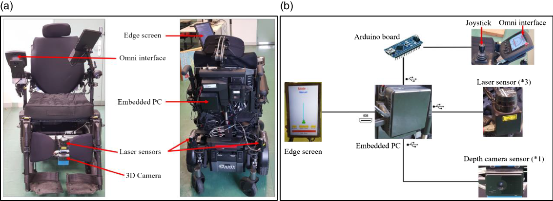
Figure 1. (a) The AMY wheelchair. (b) Hardware architecture of the SW.
Along with the laser sensors, a Terabee 3D camera (model TB-3DCAM-8060-USB) is attached with the front laser sensor. It is a time-of-flight (TOF) camera able to capture depth image of the scene with a field of view of 74° × 57°and an output resolution of 80 × 60 pixels. The depth image is made up of pixels that contain the distance from the camera plan to the nearest object. This camera is used here, for a security purpose, to detect negative obstacles (obstacles below the floor surface) in front of the wheelchair. In such a situation, the current assistance feature is deactivated and the manual mode activated.
The wheelchair is also equipped with an embedded screen to display the human–machine control interface. The joystick is used either to navigate in the interface or to drive the wheelchair in manual mode. It is equipped with a push button to simulate the mouse click.
The processing is made by an embedded PC (Intel® NUC 10 – NUC10i7FNK-1.1GHz, RAM-16Go, ubuntu 18.04 (64bits) operating system), which is connected to the edge screen, the sensors, and to the wheelchair motors via an Arduino Nano board (Fig. 1(b)). The PC runs a Robot Operating System (ROS), which is a Linux-based software framework for operating robots [37]. The Arduino board, operating as a ROS node, is responsible for receiving commands from the ROS framework and writing it on the wheelchair control system using the Omni interface, a standard market solution for powered wheelchairs.
We have implemented a ROS package for our system. The package contains a node for each functionality, topics and specific messages. We have also used third-party packages and nodes that provide useful functionalities. Figure 2 shows the graphical display of the whole system. The nodes of our package are highlighted with a red contour, and they will be detailed in the next section. Short descriptions of the third-party packages and nodes that we have used are given below:
-
- hector_mapping is a simultaneous localization and mapping (SLAM) approach that can be used without odometry and provides a 2D pose estimates of the robot at scan rate of the sensors. This node subscribes to the laser scan topic and publishes the estimated robot pose topic with a gaussian estimate of uncertainty.
-
- laserscan_multi_merger is a node of the ira_laser_tools package. It allows to easily merge multiple, same, single-scanning plane, laser scan topics into one.
-
- urg_node is a driver for the laser scan sensor. It publishes the laser scan data topic.
-
- serial_node is a node of the rosserial_python package. It is a Python implementation of the host-side rosserial connection. It automatically handles set-up, publishing and subscribing for a connected rosserial-enabled device.
-
- openni2_camera is a package for using OpenNI-compliant devices in ROS. It contains a camera node for publishing camera data.
-
- rviz is a ROS graphical interface tool for visualisation. It can display sensor values, robot pose and model, markers, etc. It can also provide operator interactions via a mouse.

Figure 2. Graphical display of the SW architecture with the corresponding ROS nodes. The nodes that we have developed are highlighted with a red circle.
3. Methodology
In the developed driving assistance system, the user and the robot trade the control of the system through different features. Each feature helps increase precision, increase security and reduce fatigue during a driving task. The user can choose a semi-autonomous operating mode (doorway crossing or wall following), an assisted mode (obstacle avoidance) or a manual mode through the HMI.
In the semi-autonomous mode, the robot entirely controls the motion but the user, as a supervisor, can interrupt or change the system’s behaviour at any time the task is executing. Conversely, in the assisted mode, the person controls the motion supervised by the robot who avoids obstacles considering the desired travelling direction indicated by the user. Lastly, in the manual mode, the user is the sole responsible for the wheelchair motions.
3.1. Human–machine interface
We have developed an intuitive and simple HMI which provides necessary information to communicate with the user and perform the right action. It contains 2D interactive markers presenting the different modes of operation, a 2D projection of the environment and a text display area (Fig. 3).

Figure 3. The human–machine interface.
The user can drive the wheelchair or interact with the graphical interface using the joystick controller. The manual mode is activated by default when the system is turned on. Then, the user can navigate on the interface by pressing the button on the joystick. Functionalities are selected by pointing the corresponding item except for the doorway crossing. In this case, the person chooses a narrow passage among the different possibilities identified by the laser sensors. The 2D view of the environment displays a model of the wheelchair and the detected narrow passages. These ones are displayed with respect to their positions and orientations to the wheelchair. A virtual forward motion axis is also added to help the user to identify the desired narrow passage. Finally, the text area displays the selected feature, the marker colour of the selected feature becomes red and the joystick returns to wheelchair driving mode.
3.2. Human–machine cooperation
The driving task for a car and by extension for an electric wheelchair can be classified into three hierarchical levels: operational (impact on the environment), tactical (local organisation) and strategic (overall planning) [Reference Michon, Evans and Schwing38]. The cooperation between human and the semi-autonomous vehicle can be established at each of these levels and according to three cases [Reference Abbink9, Reference Flemisch, Abbink and Itoh15, Reference Bourhis and Agostini16]: the robot controls the movement and the person supervises (red lines in Fig. 4), the person controls the movement and the robot supervises (green lines in Fig. 4) and both entities simultaneously control the movement (black lines in Fig. 4).

Figure 4. Human–SW cooperation (solid lines: implemented features, dotted lines: other possible features).
In the wall following and doorway crossing features, the robot controls the motion. However, sensor data, regardless of the technology used, cannot achieve perfect reliability, especially in congested environments. In particular, the laser rangefinders used in this study only see in a plane and are therefore subject to errors in the event of an obstacle that is not filled. In order to compensate for these robot imperfections, the user is then given the possibility to intervene punctually in semi-autonomous mode (“combined control”). At the tactic level, the person can take the control in manual mode simply by activating the joystick to rectify a trajectory planned by the robot ((4) in Fig. 4). As soon as he releases the joystick, the automatic movement resumes. This possibility of a punctual intervention can also be interesting at a strategic level ((1) in Fig. 4) in the case of a wall following: in an intersection, the person can easily remove the ambiguity on the path to follow.
In assisted mode, if the person who control the wheelchair gets too close to an obstacle, the supervising robot takes the control and goes around it. During this manoeuvre, the user continues to indicate the desired direction via the joystick and control is returned to the user as soon as the obstacle is avoided. This is the tactical level ((5) in Fig. 4). For all three features, a security is provided if a negative obstacle is detected. The current automatic motion is then stopped, and the manual mode is activated. Simultaneously information is communicated to the user on the interface screen. The robot acts here at the operational level ((8) in Fig. 4). Conversely, it is always possible in case of failure of the robot, such as a defect in the reading of the sensors, to stop the wheelchair by pressing the joystick button ((7) in Fig. 4).
3.3. Semi-autonomous features
3.3.1. Doorway crossing
This feature allows the user to automatically cross a narrow passage. It is based on the algorithm already described in ref. [Reference Leishman, Horn and Bourhis32]. A narrow passage is first selected by the user among the different plausible solutions (widths between 85 and 200 cm) in the direction of wheelchair motion. A sequence of target points is then defined (Fig. 5) that the wheelchair will try to reach successively (Fig. 6). To avoid recalculating these points at each iteration, the algorithm [Reference Leishman, Horn and Bourhis32] has been blended here with a SLAM approach in order to locate the wheelchair in a local map of the environment.

Figure 5. Local map and a real view of an environment on which a narrow passage is detected. The local map displays the markers of the detected narrow passage, the target points and the initial position of the wheelchair.
Then, the wheelchair moves to cross the narrow passage by tracking the target points. The angular velocity of the wheelchair is given by the error between its orientation and the target point orientation. The linear velocity of the wheelchair is obtained by computing the euclidian distance between its current position and the target point position on the local map. The wheelchair localisation is estimated at every scan rate in the local map. Finally, when the doorway is crossed, the wheelchair control returns to manual mode and the local map must be reseted. The algorithm of the doorway crossing is given below:

Figure 6. Path travelled by the wheelchair through the narrow passage and its final position.

3.3.2. Wall following
The second feature allows the user to safely and automatically following a wall on his left or right. Unlike a corridor following feature [Reference Burhanpurkar, Labbé, Guan, Michaud and Kelly26, Reference Lee, Chiu and Kuo28], it does not require a phase of features recognition in the environment. This mode of operation has been proposed for environments with wide and long corridors such as rehabilitation centres. The algorithm of this feature has also been already described in ref. [Reference Leishman, Horn and Bourhis32]. Its main idea is to keep the wheelchair moving at a safe distance from the wall by tracking a target point. Three area (right, left and front) and three distances (
 ${d_{right}}$
,
${d_{right}}$
,
 ${d_{left}}$
and
${d_{left}}$
and
 ${d_{front}}$
) are defined for this purpose (Fig. 7). Distances are measured from the wheelchair to the nearest obstacle in their respective zones. In the case of a left wall following, the role of the
${d_{front}}$
) are defined for this purpose (Fig. 7). Distances are measured from the wheelchair to the nearest obstacle in their respective zones. In the case of a left wall following, the role of the
 ${d_{left}}$
distance is to keep the wheelchair at a safe distance
${d_{left}}$
distance is to keep the wheelchair at a safe distance
 ${d_{safety}}$
of the wall to follow. The
${d_{safety}}$
of the wall to follow. The
 ${d_{right}}$
distance adjusts the safety distance in case of lack of space. The
${d_{right}}$
distance adjusts the safety distance in case of lack of space. The
 ${d_{front}}$
distance controls the linear velocity of the wheelchair.
${d_{front}}$
distance controls the linear velocity of the wheelchair.

Figure 7. The control areas around the wheelchair and their corresponding distances for a wall following feature.
Then, theses distances are used to determine the polar coordinates
 $\left( {{\rho _{target}},\;{\theta _{target}}} \right)$
of the target point. The algorithm of the right wall following is given below:
$\left( {{\rho _{target}},\;{\theta _{target}}} \right)$
of the target point. The algorithm of the right wall following is given below:

Figure 8 shows an example of path during a wall following feature. One can note that the wheelchair adapts its safety distance with respect to obstacles positions and generates a safe and smooth trajectory.

Figure 8. Autonomously travelled path by the wheelchair through a corridor with obstacles, in the case of a right wall following.
3.3.3. Assisted mode
This feature is proposed to assist the user to safety travelling with his/her wheelchair using the joystick. It assists the user to avoid obstacles by considering the desired forward direction. It stops the wheelchair to prevent a collision in the case of a backward travelling. The feature controls both speed and steering of the wheelchair. The speed is always reduced in a way that the wheelchair cannot collide with the obstacles in the environment. The steering is controlled to avoid obstacles by considering the direction indicated by the user via the joystick. The avoidance manoeuvre is based on the wall following feature. Thus, if the obstacle is in the right/left side, the right/left wall following must be activated until the obstacle is circumvented. During the avoidance manoeuvre, the person continues to indicate a direction with the joystick. Once the obstacle has been avoided, the control of the wheelchair is given back to the person in the last direction indicated.
The wheelchair has a rather complex shape. To avoid obstacles, we must determine a safety area around it. Then, the safety distance should be calculated based on the safety area and the travelling direction. Since obstacle avoidance will be activated in a forward travelling, we have determined two safety areas in the front of the wheelchair. These areas correspond to two circles of radius
 $r\;$
(
$r\;$
(
 $2r$
corresponds to the width of the wheelchair with a safety margin) and
$2r$
corresponds to the width of the wheelchair with a safety margin) and
 $R$
. Their centres are the front laser. The radius
$R$
. Their centres are the front laser. The radius
 $R$
of the second circle must be large enough to anticipate an obstacle. Thus, when an obstacle enters the radius
$R$
of the second circle must be large enough to anticipate an obstacle. Thus, when an obstacle enters the radius
 $R$
, the system activates the obstacle avoidance feature to allow the wheelchair to safely avoid it. The circle of radius
$R$
, the system activates the obstacle avoidance feature to allow the wheelchair to safely avoid it. The circle of radius
 $r\;$
is used to prevent a collision when the avoidance manoeuvre is not possible. In the case of a backward travelling, the safety area corresponds to a rectangle of width
$r\;$
is used to prevent a collision when the avoidance manoeuvre is not possible. In the case of a backward travelling, the safety area corresponds to a rectangle of width
 $2r$
and length
$2r$
and length
 $l$
which corresponds to the length of the wheelchair with a safety margin. Figure 9(a) shows the safety areas. The computation of the safety distance is based on the safety areas and the direction
$l$
which corresponds to the length of the wheelchair with a safety margin. Figure 9(a) shows the safety areas. The computation of the safety distance is based on the safety areas and the direction
 $\theta $
of the wheelchair indicated by the user via the joystick. Based on
$\theta $
of the wheelchair indicated by the user via the joystick. Based on
 $\theta $
, we have divided the safety area around the wheelchair into six regions (Fig. 9(b)) from which we deduce the safety distances. These ends are defined as
$\theta $
, we have divided the safety area around the wheelchair into six regions (Fig. 9(b)) from which we deduce the safety distances. These ends are defined as
 $l/\left| {cos\left( {\pi + \theta } \right)} \right|$
for the back left region (BLR),
$l/\left| {cos\left( {\pi + \theta } \right)} \right|$
for the back left region (BLR),
 $r/\left| {cos\left( {\frac{\pi }{2} + \theta } \right)} \right|$
for the side left region (SLR),
$r/\left| {cos\left( {\frac{\pi }{2} + \theta } \right)} \right|$
for the side left region (SLR),
 $r$
for the front left region (FLR) and the front right region (FRR),
$r$
for the front left region (FLR) and the front right region (FRR),
 $r/\left| {cos\left( {\frac{\pi }{2} - \theta } \right)} \right|$
for the side right region (SRR), and
$r/\left| {cos\left( {\frac{\pi }{2} - \theta } \right)} \right|$
for the side right region (SRR), and
 $l/\left| {cos\left( {\pi - \theta } \right)} \right|$
for the back right region (BRR).
$l/\left| {cos\left( {\pi - \theta } \right)} \right|$
for the back right region (BRR).

Figure 9. (a) Safety areas around the wheelchair and (b) the corresponding safety regions to compute a safety distance.
To determine the avoidance manoeuvre, the direction indicated by the user with the joystick is considered. Respecting the direction angle
 $\theta $
and two parameters, the angles α (
$\theta $
and two parameters, the angles α (
 $\alpha = \frac{\pi }{4}$
) and
$\alpha = \frac{\pi }{4}$
) and
 $\beta(\beta = {\rm{arctan}}(\frac{r}{l}))$
represented Fig. 9(b), the direction can belong to one of six categories as shown in Fig. 10. At every scan rate, the system gets the local map for obstacles based on this direction employing the corresponding category and safety regions (Fig. 10). Therefore, the system assesses the current situation to react respecting the user steering direction. In the case of a forward movement (Left Forward, Front Forward and Right Forward), if an obstacle is detected in the safety region, the system controls the direction of the wheelchair to avoid it. In the case of a backward motion (Left Backward, Back Backward and Right Backward), the system stops the wheelchair to prevent collision with obstacles.
$\beta(\beta = {\rm{arctan}}(\frac{r}{l}))$
represented Fig. 9(b), the direction can belong to one of six categories as shown in Fig. 10. At every scan rate, the system gets the local map for obstacles based on this direction employing the corresponding category and safety regions (Fig. 10). Therefore, the system assesses the current situation to react respecting the user steering direction. In the case of a forward movement (Left Forward, Front Forward and Right Forward), if an obstacle is detected in the safety region, the system controls the direction of the wheelchair to avoid it. In the case of a backward motion (Left Backward, Back Backward and Right Backward), the system stops the wheelchair to prevent collision with obstacles.

Figure 10. The six categories of directions, their angles and corresponding safety regions. Front Forward (-
 ${\rm{\alpha }} \le {\rm{\theta }} \le {\rm{\alpha }}$
, FLR, FRR), Left Forward(
${\rm{\alpha }} \le {\rm{\theta }} \le {\rm{\alpha }}$
, FLR, FRR), Left Forward(
 ${\rm{\alpha }} \le {\rm{\theta }} \le \frac{{\rm{\pi }}}{2}$
, FLR, SLR), Left Backward (
${\rm{\alpha }} \le {\rm{\theta }} \le \frac{{\rm{\pi }}}{2}$
, FLR, SLR), Left Backward (
 $\frac{{\rm{\pi }}}{2} \le {\rm{\theta }} \le {\rm{\pi }} - {\rm{\beta }}$
,FLR, SLR, BLR, BRR, SRR), Backward (
$\frac{{\rm{\pi }}}{2} \le {\rm{\theta }} \le {\rm{\pi }} - {\rm{\beta }}$
,FLR, SLR, BLR, BRR, SRR), Backward (
 ${\rm{\pi }} - {\rm{\beta }} \le {\rm{\theta }} \le {\rm{\pi \;or}} - {\rm{\pi }} \le {\rm{\theta }} \lt - {\rm{\pi }} + {\rm{\beta }}$
, BRR, BLR), Right Backward (
${\rm{\pi }} - {\rm{\beta }} \le {\rm{\theta }} \le {\rm{\pi \;or}} - {\rm{\pi }} \le {\rm{\theta }} \lt - {\rm{\pi }} + {\rm{\beta }}$
, BRR, BLR), Right Backward (
 $ - {\rm{\pi }} + {\rm{\beta }} \lt {\rm{\theta }} \le - \frac{{\rm{\pi }}}{2}$
, FRR, SRR, BRR, BLR, SLR), Right Forward (
$ - {\rm{\pi }} + {\rm{\beta }} \lt {\rm{\theta }} \le - \frac{{\rm{\pi }}}{2}$
, FRR, SRR, BRR, BLR, SLR), Right Forward (
 $ - \frac{{\rm{\pi }}}{2} \lt {\rm{\theta }} \le - {\rm{\alpha }}$
, FRR, SRR).
$ - \frac{{\rm{\pi }}}{2} \lt {\rm{\theta }} \le - {\rm{\alpha }}$
, FRR, SRR).
This assisted mode is developed based on the wall following feature. It controls the wheelchair direction to avoid obstacles at the corresponding real-world position relative to the centre of the wheelchair driving axle (on the left side or in the right side). If the wheelchair would hit the obstacle with its front right/left, it will try to avoid it using the right/left wall following feature. Then, if the user does not react to the change in direction during the avoidance action, the system will return to the direction indicated by the user after the obstacle was circumvented. Therefore, if there are no more obstacles, the user is in full control of the wheelchair.
4. Experimental results
The described above features have been tested in laboratory; the robustness and effectiveness of each function were evaluated in different movements and situations. Secondly, the cooperation between the SW and the user in different situations has been studied. The following describes some examples of paths in the different control modes proposed. The objective is to highlight the interest of this cooperative architecture. In these tests, the maximal speeds that the wheelchair can reach were fixed to 3.7 and 1.4 km/h for linear and angular speed, respectively.
4.1. Doorway crossing
Firstly, the effectiveness of the doorway crossing feature is evaluated. The behaviour of the wheelchair was studied while crossing a doorway from different positions and orientations. The efficiency of the doorway feature was measured as a function of the narrow passage width and the wheelchair starting angle. The wheelchair is 70 cm wide and 100 cm long. The experiments showed that this feature allows the wheelchair to automatically cross a narrow passage of more than 80 cm width, whatever the angle of the starting point. In each case, the wheelchair tracked the doorway axis to cross it in correct position and orientation. For a narrow passage with a width between 71 and 80 cm, the intervention of the user is sometimes necessary for a trajectory correction. The experiments also showed that this feature allows the wheelchair to automatically cross a narrow passage if it is in a corridor with a width greater than 165 cm, whatever the starting angle. Furthermore, for a narrow passage located in a corridor with a width between 120 and 165 cm, the feature allows the wheelchair to automatically cross such a passage if it is in front of it.
Secondly, to illustrate the cooperation between this autonomous feature and the user, the situation in Fig. 11(b) has been considered. The wheelchair has been placed in a corridor with two narrow passages, one to its right and the other to its left. The door of the left narrow passage was intentionally half-closed (Fig. 11(a)). Then, we have selected via the graphical interface to move through the left narrow passage. Thus, the wheelchair starts to manoeuvre to cross it. Figure 12 shows the travelled path of the wheelchair. When it arrives in the middle of the narrow passage, it detects an obstacle in front of it. This forces the wheelchair to stop. In this case, the user assesses the situation, whether he/she could push the obstacle or not. Therefore, he/she has chosen to push it. Then, the autonomous feature took over to finalise the manoeuvre and bring the wheelchair through the door.

Figure 11. Wheelchair placed in a corridor with two doorways. The graphical interface highlight the detected passages.

Figure 12. Local map of the environment and the autonomously travelled path while crossing a doorway. The trajectory shows the cooperation between the user and the autonomous feature.
To further highlight the cooperation between the user and doorway crossing feature, the situation in Fig. 13 is also considered. A table has been placed near the door. Its height is such that the laser sensor can only detect its feet. The person supervising the automatic movement realises that the initiated trajectory will cause a collision. He then briefly regains control to deviate the wheelchair. When he releases the joystick, the automatic movement resumes. The figure shows the path travelled by the wheelchair and the part where the user had to intervene to avoid the obstacle.

Figure 13. (b) Image of a doorway with an obstacle near to it and (a) local map of the environment and the autonomously travelled path while crossing a doorway. The trajectory shows the cooperation between the user and the robot.
4.2. Wall following
To evaluate the effectiveness of this feature, the behaviour of the wheelchair was observed when it is travelling a long corridor with and without narrowing and widening. The obtained trajectory is shown in Fig. 14, in which the travelled path has been represented and different steps have been highlighted. In step 1, the wheelchair moves forward in the middle of the corridor. Then, in the crossing, the user intervenes to change its direction using the joystick (turn left). In step 2, the wheelchair decreases its safety distance because the corridor is narrowing. Then, it keeps in the middle until the corridor is widening to increase its safety distance (step 3). Then, at the intersection, the user reacts again to choose the desired direction (turn left). In step 4, the wheelchair avoids the objects to its right side by turning slightly to the left and after that it gradually comes back towards the middle of the corridor.

Figure 14. Map of a long corridor travelled by the wheelchair using the left following feature. The travelled path highlights the places where the user corrected the trajectory of the wheelchair.
This test shows that the wall following feature is effective by generating a safe and smooth trajectory. However, the user must intervene in a crossing to choose a desired direction. To explain that, Fig. 15 shows the corrected and not corrected trajectory of the wheelchair in a corridor with an intersection. In this test, the right wall following feature was used. Figure 15(a) shows the travelled path of the wheelchair without user intervention. So, from the starting point, it moves forward to the crossing. Then it begins to turn slightly to the right corridor. However, because it detects the right wall of the front corridor, the wheelchair continues moving forward by increasing its safety distance. The wheelchair would have continued to turn right if the intersection were wide enough. Figure 15(b) shows an example of a cooperation between the robot and the user. In this case, the user had to intervene to choose a desired direction (turn right). Thus, the user has taken control of the wheelchair via the joystick to slightly correct its direction. Then, the autonomous feature took over by turning the wheelchair completely to the right and adjusting its safety distance respecting the corridor width.

Figure 15. A local map and the travelled path of the wheelchair in a corridor with a crossing. (a) The wheelchair autonomously travelled without intervention of the user and (b) the user intervened to change the wheelchair direction to the right corridor.
The second example highlights the cooperation between the user and the robot. A table is placed on the right side of the corridor. Its height is such that the laser sensor can only detect its feet. Figure 16 shows an image and a view of the corridor and the path travelled by the wheelchair using the left following feature. The part of the trajectory where the user had to intervene to avoid the obstacle is highlighted with a red colour. One can note that the wheelchair begins to adapt its safety distance respecting the table feet and the right wall. However, because the laser sensors cannot detect the base of the table, the safety distance does not take it into account. Therefore, the wheelchair cannot correctly avoid the table and the user’s intervention is of a crucial importance in such a situation.

Figure 16. Image view and local map of a corridor with an obstacle. The cooperation between the user and the left wall following feature is highlighted with a red corridor in the travelled path.
4.3. Assisted mode
To evaluate the effectiveness of the assisted mode, the wheelchair was placed in a corridor containing obstacles on the left and right. Figure 17 shows the path travelled by the wheelchair using this feature. From this trajectory, one can note that the user and the robot share control of the wheelchair alternately. The user has full control of the wheelchair until an obstacle in its forward motion axis has been detected. In this case, the robot takes over control of the wheelchair to enable it to avoid the obstacle. Then, the user takes back the control when the obstacle is avoided.

Figure 17. Local map of a corridor with obstacles and the path travelled by the wheelchair using the assisted mode.
4.4. The whole system
To evaluate the whole system, the driving behaviour of the wheelchair was observed along a trajectory with doors, obstacles and narrowing. Three driving modes were considered: manual, semi-autonomous and assisted. For all three operating modes, the wheelchair was driven by an experienced, healthy person. The trajectory performed manually by this person (Fig. 18) can be considered as a reference trajectory. In the other two cases (use of wall following and doorway crossing (Fig. 19) or assisted mode and doorway crossing (Fig. 20)), the trajectories obtained are close to the reference trajectory. However, it can be noted that the last doorway is achieved in a smoother trajectory in manual mode. This is because in this configuration the driver detects the door earlier than the automatic system and can therefore anticipate it better.

Figure 18. Map of a long corridor travelled by the wheelchair using the manual mode.
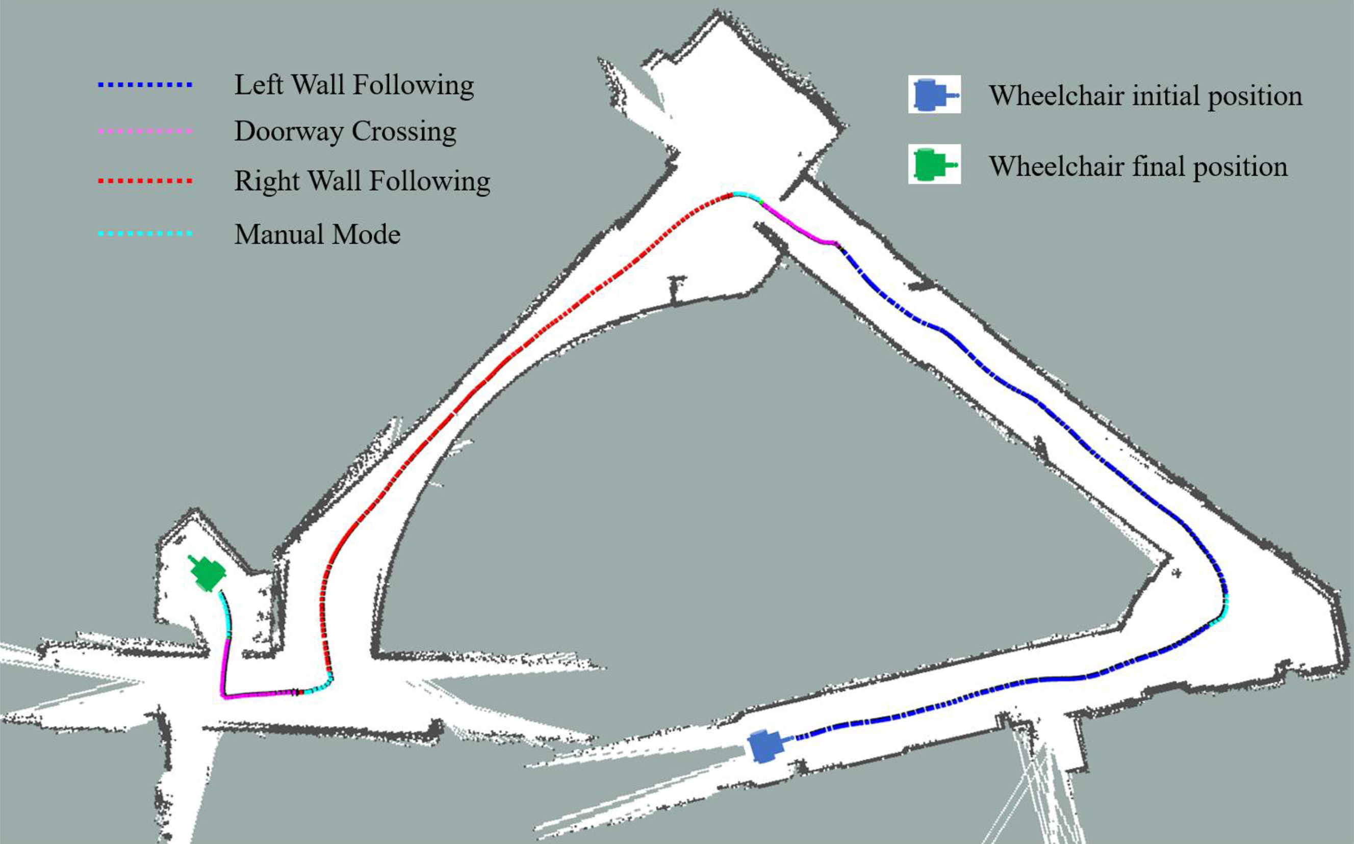
Figure 19. Map of a long corridor travelled by the wheelchair using the wall following and the doorway crossing features. The travelled path highlights the places where the user calls every feature.

Figure 20. Map of a long corridor travelled by the wheelchair using the assisted mode and the doorway crossing feature. The travelled path highlights the places where the user calls every feature.
5. Discussion
The proposed system aims to assist the driving of a powered wheelchair. The user can drive the wheelchair, according to his/her needs, either in manual mode, assisted mode or by using a semi-autonomous feature. A graphical interface provides a convenient way to switch from one mode to another. It is important to note that driving assistance is not imposed on the user, who therefore retains complete freedom of choice. The features of wall following or door crossing are called if necessary, in case of fatigue or difficult manoeuvres. Similarly, in assisted mode, the person can decide to avoid an obstacle himself, in which case he retains full control of the wheelchair.
Other situations than those presented to illustrate the possibility of a “combined control” can be imagined. In the case of an obstacle completely obstructing the passage in semi-autonomous mode, for example, the person can take over manually to develop the appropriate behaviour, push the obstacle or look for another path. It can also be noted that while some of these examples are technically specific to the implemented SW, their principles are generic. In particular, the reliability of the sensor system can be improved at the cost of additional economic cost and heavier computer processing. However, a total reliability seems at present unrealistic in complex environments.
Different modes of human–machine cooperation have been implemented and tested. The choice of these modes is based on the assumption that the user has sufficient cognitive abilities to understand the driving situation. He can thus be considered as a last resort in case of system blockage. In this capacity, he has a non-secure manual mode where no movement is forbidden. Generally speaking, the choice of the different modes of cooperation presented Fig. 4 depends on the cognitive and sensory capacities of the two entities. For example, the robot could help a person at a strategic level ((2) in Fig. 4), if the latter has cognitive difficulties with regard to orientation and route planning.
The choice was made in this study to implement a traded control rather than a shared control. In both cases, it is assumed that the person has minimal cognitive, sensory and physical abilities to operate a powered wheelchair. In this case, therefore, assistance is provided to the driver with the aim of facilitating the performance of complex manoeuvres and increasing his safety. In both modes, it is essential to establish clear communication between human and machine. This is often more complex in shared control ((9) in Fig. 4) where the information is sent back to the person haptically via a force feedback joystick or simply by the movements of the wheelchair. In traded control as in this study, simple messages on the graphical interface allow to understand what the robot is doing, especially when it chooses to change its operating mode. On the other hand, the person’s specific interventions (“combined control”) presuppose that the person has a good understanding of the robot’s functioning and limits, particularly its sensory limits.
Finally, a last point will require an extension to this work: it will be a question of ensuring that the human–machine interaction of the proposed cooperative system does not induce an excessive mental workload for the user. Thus in ref. [Reference Leishman, Monfort, Horn and Bourhis39], the authors show that the developed mode of traded control associated with a “deictic” interface leads to an increase in the executive abilities component of the mental load.
6. Conclusion
This paper presented a traded control SW. Two semi-autonomous features, a doorway crossing and a wall following, allow a specific human intervention, called “combined control,” to correct an erroneous trajectory or provide strategic information. An assisted mode is also available which allows an automatic obstacle avoidance intervention during a manual control. Each entity, human or machine, can therefore be supervised by the other. Every functionality of the proposed system has been tested in different situations and trajectories. The obtained results show that the system and the user cooperate to increase the reliability and the security while driving the wheelchair. The technical efficiency having been demonstrated, and future work will consist of experimenting the system on end users with two objectives: to verify that the demand for mobility assistance is well met on the one hand and to ensure that the reduction of the physical workload is not to the detriment of the mental workload on the other hand.
Acknowledgements
The authors would like to thank the Région Grand Est (France) for funding this work.
Competing interests
The authors declare none.
Author contributions
Y. Ech-Choudany and R. Grasse developed the code and carried out the experiment. Y. Ech-Choudany and G. Bourhis wrote the manuscript. G. Bourhis directed the work. R. Stock and O. Horn contributed to the work. All authors approved the version of the manuscript to be published.


