1. INTRODUCTION
The study on the interactions between ion beams and plasmas have received considerable attention. These studies have been a topic of great interest due to their significant applications in modern sciences and technologies, such as the cooling of heavy-ion beams by electrons (Sorensen & Bonderup, Reference Sorensen and Bonderup1983; Goldman & Hofmann, Reference Goldman and Hofmann1990), the high-energy dense matter physics (Ng et al., Reference Ng, Perror, Dharma-Wardana and Foord2005; Drake, Reference Drake2006), the heavy-ion inertial fusion (Renk et al., Reference Renk, Mann and Torres2008; Ter-Avetisyan et al., Reference Ter-Avetisyan, Schnuerer, Polster, Nickles and Sandner2008; Zhao et al., Reference Zhao, Hu, Cheng, Wang, Peng, Golubev, Zhang, Lu, Zhang, Zhou, Wang, Xu, Ren, Li, Lei, Sun, Zhao, Wang, Wang and Xiao2012), etc.
In the last decade, many experimental (Hoffmann et al., Reference Hoffmann, Blazevic, Ni, Rosmej, Roth, Tahir, Tauschwitz, Udrea, Varentsov, Weyrich and Maron2005; Zhao et al., Reference Zhao, Hu, Cheng, Wang, Peng, Golubev, Zhang, Lu, Zhang, Zhou, Wang, Xu, Ren, Li, Lei, Sun, Zhao, Wang, Wang and Xiao2012) and theoretical (Boine-Frankenheim & D'avanzo, Reference Boine-Frankenheim and D'avanzo1996; Franchetti et al., Reference Franchetti, Hofmann, Fischer and Zimmermann2009; Hu et al., Reference Hu, Song and Wang2012) investigations have been made to study the energy deposition of the ion beams in plasmas. The linearized theories, such as the dielectric theories (Bringa & Arista, Reference Bringa and Arista1995; Deutsch & Fromy, Reference Deutsch and Fromy1995; Zwicknagel & Deutsch, Reference Zwicknagel and Deutsch1997), and the simulation method, such as the particle-in-cell (PIC) method (Zhang et al., Reference Zhang, Zhao, Qi, Xiao, Duan and Yang2015), are used to study the collective effects of the beam ions on the stopping power.
Recently, the focusing of the ion beam in plasmas (Kaganovich et al., Reference Kaganovich, Startsev and Davidson2002, Reference Kaganovich, Startsev, Sefkow and Davidson2007; Hu et al., Reference Hu, Chen and Wang2014) has received more and more attention. This is due to the reason that in practical applications, the beams are diffused into larger spot sizes and smaller density due to the strong space-charge force of the beam ions. However, the larger spot sizes correspond to the larger beam driver building cost. In addition, the energy that delivered by the beam to the target is inversely proportional to the beam radius and length. Thus, the investigation of ion beams focusing in background plasmas have been extensively studied in recent years. Kaganovich et al., (Reference Kaganovich, Startsev and Davidson2004) have investigated the nolinear charge and current neutralization of an ion beam pulse in a pre-formed plasmas using the PIC simulation and fluid calculation. It is found that the plasma electrons tend to neutralize the strong space-charge force of the beam. Thus, the background plasma can be provided as an ideal media for ion beam pulses propagation. In addition, they have found that the beam ions are always pinched during beam propagation in plasmas. Hu et al. (Reference Hu, Song, Zhao and Wang2013) have investigated the propagation of intense ion beams through background plasmas in the presence of external applied magnetic fields. It is shown that the effective electron gyroradius is found to be an important parameter for the current neutralization of ion beams propagating in the magnetic fields. In the experimental investigations, Roy et al. (Reference Roy, Yu and Henestroza2005) have firstly demonstrated the longitudinal compression of a velocity-tailored, intense neutralized K + beam at 300 keV, 25 mA. Sefkow et al. (Reference Sefkow, Davidson and Gilson2009) have also investigated the compression of intense K + beams in space and time. It is found that the plasmas enhance the beam peak current by a factor of 10 and pulse duration <5 ns. To our knowledge, most of these investigations focus on the propagation of the medium-length beams. There are few investigations on the long beams propagating in plasmas, which is also important in experimental researches and practical applications. To fully understand the focusing effects of the ion beams in the plasmas, the investigations of the long beam propagating in background plasma need to be further studied.
In this paper, a two-dimensional (2D) PIC simulation is carried out to study a proton beam with the long length propagating in plasmas using the code of VORPAL (Nieter & Cary, Reference Nieter and Cary2004). Both the beam proton and plasma particles are treated by the PIC method. In this way, the interactions among the beam ions, plasma electrons and plasma ions are taken into consideration. Then the focusing effects of the proton beam propagating in background plasmas are discussed in detail.
Section 2 introduces the numerical method and physical model used in our simulation. In Section 3, the simulation results are presented and discussed. Finally, conclusions are made in Section 4.
2. NUMERICAL METHOD AND PHYSICAL MODEL
The interactions between the charged particles in the plasmas are composed of two parts: the electromagnetic (EM) interactions due to the plasma collective motion (the long Coulomb interaction) and the electrostatic interactions (the short Coulomb interaction). Taking into the difference between these interactions, the electrostatic interactions, such as the electron–ion collision and electron–ion recombination, are not considered in this paper. A 2D3 V EM PIC simulation is carried out to take into consideration the EM interactions and study the focusing effects for a proton beam in hydrogen plasmas using the code of VORPAL (Nieter & Cary, Reference Nieter and Cary2004), which is a arbitrarily dimensional, hybrid plasma, and beam simulation code. The kinetic model incorporated in VORPAL is based on the PIC algorithm. In the EM simulation, the electric and magnetic fields are updated using the finite-difference-time-domain solver based on the Faraday's equation,
and the Ampere–Maxwell equation,
Then, the electric and magnetic fields are interpolated to the location of the charged particle. The particle position and velocity are updated using the equations of motion:
where r, v, q, and m are the position, velocity, charge, and mass of the charged particles, respectively, including the beam protons, plasma electrons, and plasma ions.
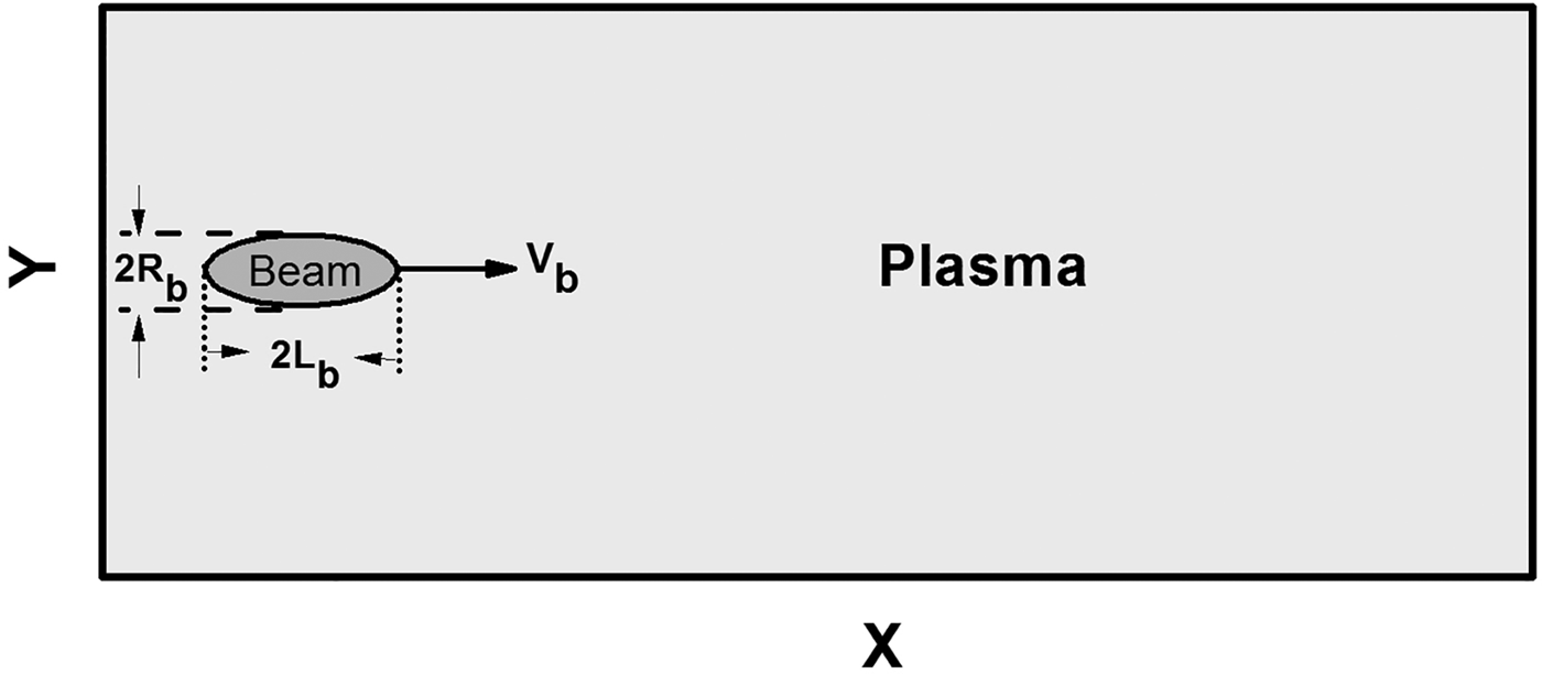
In our simulation, a 2D three-velocity (x, y, V x, V y, V z) plasma model is used as shown in Figure 1. The 2D model is composed of the longitudinal (x) and radial (y) directions. Here the longitudinal (x) and radial (y) directions represent parallel and perpendicular to the direction of the beam motion, respectively. The charged particles are considered to move in the x–y plane, with the velocity in the z-direction V z also tracked, which goes partway to a three-dimensional (3D) model. All charged particles extend along the z-direction and are represented by the rods. In this configuration, the movement in the y-direction and the z-direction is the same. Hence, to reduce the computational cost, one can make a 2D particle simulation in the x–y plane. The drift and focusing motion of the charged particles can be obtained in the y-directions. The acceleration and deceleration of charged particles can be tracked in the x-direction. The simulation region lays spatially from x = 0 to x = L x, and from y = 0 to y = L y. In order to assure that the plasma and field perturbations do not reach the boundaries, the simulation box is composed of N x = 6500 grids in the x-direction and N y = 512 grids in the y-direction. The simulation box is fixed to the laboratory frame. Periodic boundary condition in the y-direction and open boundary condition in the x-direction are adopted. Taking into account the Courant–Friedrichs–Lewy limit, the time step Δt = 2.576 × 10⁻¹³ s is chosen. The spatial step Δx = 1.486 × 10⁻⁴m (=2 × the Debye shielding length) and Δy = 1.486 × 10⁻⁴m (=2 × the Debye shielding length) are chosen. The number of macro-particles per cell is chosen to be 50 for all kinds of particles involved in the simulation (the plasmas electrons, ions, and the beam protons). To improve the overall accuracy and reduce the numerical noise, we have changed the number of macro-particles per cell from 50 to 200. It is found that the influence of the number of macro-particles per cell is negligible.

Fig. 1. A 2D model: the propagation of the ion beam pulse in plasmas.
A fully ionized hydrogen plasma (H +, e −) is placed in the box. The plasma is assumed to be collisionless, uniform, and non-magnetized in a steady state. Plasma parameters used in the simulation are as follows: initial plasma electron density N e0 = 1.0 × 10¹⁷m−3, initial plasma ion density N e0 = 1.0 × 10¹⁷m−3, initial plasma electron temperature T e0 = 10 eV, and initial plasma ion temperature T i0 = 10 eV. Initially, the proton beam is injected from the left boundary and the direction of the beam velocity is parallel to the x-direction. The beam velocity V b is 0.3c. The initial velocity for each pulse ion is the same, and the emittance of the beam is zero. The beam half-length L b will vary according to the requirements and the radius R(x) is initially related to the coordinate in the x-direction by the relation of ![]() $R(x) = {R_{\rm b}}\sqrt {1 - {{((x - {L_{\rm b}})/{L_{\rm b}})}^2}} $, where R b is set equal to 0.1 × 10⁻³m. The density profile of the ion beam pulse is initially a Gaussian distribution, which will also vary according to the requirements.
$R(x) = {R_{\rm b}}\sqrt {1 - {{((x - {L_{\rm b}})/{L_{\rm b}})}^2}} $, where R b is set equal to 0.1 × 10⁻³m. The density profile of the ion beam pulse is initially a Gaussian distribution, which will also vary according to the requirements.
3. SIMULATION RESULTS AND DISCUSSION
3.1. Charge neutralization
We first investigate the charge neutralization conditions for the proton beams propagating in the plasmas. The density profile of the ion beam pulse is initially a Gaussian distribution ![]() ${N_{\rm b}}(x,y) = {N_{{\rm b0}}}{\rm exp}\,( - {(x - {L_{\rm b}})^2}/{(0.4 \times {L_{\rm b}})^2})\,{\rm exp}$
${N_{\rm b}}(x,y) = {N_{{\rm b0}}}{\rm exp}\,( - {(x - {L_{\rm b}})^2}/{(0.4 \times {L_{\rm b}})^2})\,{\rm exp}$![]() $( - {(y - {R_{\rm b}})^2}/0.4 \times R_{\rm b}^2 ),$ where N b0 is 0.5N e0 = 0.5 × 10¹⁷m−3. The beam half-length L b is 0.3 πV b/ωe. Figure 2 shows the density of the proton beam (normalized by N e0) propagating in plasmas at time (a) t = 1.48 ns, (b) t = 5.92 ns, and (c) t = 10.36 ns. It is found that in the process of the beam propagation, the radius and length of the proton beam become larger. In addition, the proton beam density becomes smaller as the time progresses. This is due to the fact that when the beam of positively charged particles moves through the plasma, plasma electrons experience the beam's attraction and are accelerated to the beam. The negative plasma electrons gathered around the beam can neutralize the space charge of the beam positive ions, which results in the beam's charge neutralization phenomenon. Kaganovich et al. (Reference Kaganovich, Stvets and Startsev2001) have found that for certain background plasma, the plasma electrons’ response time to the beam's disturbance is 2 π/ωe, which is corresponding to the plasma oscillation periods. The ωe is the plasma electron frequency and m e is the electron mass. For this beam, the disturbance duration time τb to the plasma electrons is 2L b/Vb( = 0.6 π/ωe), which is smaller than the plasma electron response time. The beam moves so fast that the plasma electrons do not have enough time to response to the attraction from the beam ions, which results in that there are not enough electrons gathered around the beam and the beam charge is not well neutralized. However, if the disturbance duration time of the beam is longer than the plasma electrons’ response time, the plasma electrons have much time to accelerate to the beam. The gathered plasma electrons correspond to the beam ions’ charge, which results in the beam charge neutralization completely. Thus, the charge neutralization condition is that the beam duration time 2L b/V b is longer than the plasma electron response time 2 π/ωe, that is, the half-length of the beam L b is longer than πV b/ωe.
$( - {(y - {R_{\rm b}})^2}/0.4 \times R_{\rm b}^2 ),$ where N b0 is 0.5N e0 = 0.5 × 10¹⁷m−3. The beam half-length L b is 0.3 πV b/ωe. Figure 2 shows the density of the proton beam (normalized by N e0) propagating in plasmas at time (a) t = 1.48 ns, (b) t = 5.92 ns, and (c) t = 10.36 ns. It is found that in the process of the beam propagation, the radius and length of the proton beam become larger. In addition, the proton beam density becomes smaller as the time progresses. This is due to the fact that when the beam of positively charged particles moves through the plasma, plasma electrons experience the beam's attraction and are accelerated to the beam. The negative plasma electrons gathered around the beam can neutralize the space charge of the beam positive ions, which results in the beam's charge neutralization phenomenon. Kaganovich et al. (Reference Kaganovich, Stvets and Startsev2001) have found that for certain background plasma, the plasma electrons’ response time to the beam's disturbance is 2 π/ωe, which is corresponding to the plasma oscillation periods. The ωe is the plasma electron frequency and m e is the electron mass. For this beam, the disturbance duration time τb to the plasma electrons is 2L b/Vb( = 0.6 π/ωe), which is smaller than the plasma electron response time. The beam moves so fast that the plasma electrons do not have enough time to response to the attraction from the beam ions, which results in that there are not enough electrons gathered around the beam and the beam charge is not well neutralized. However, if the disturbance duration time of the beam is longer than the plasma electrons’ response time, the plasma electrons have much time to accelerate to the beam. The gathered plasma electrons correspond to the beam ions’ charge, which results in the beam charge neutralization completely. Thus, the charge neutralization condition is that the beam duration time 2L b/V b is longer than the plasma electron response time 2 π/ωe, that is, the half-length of the beam L b is longer than πV b/ωe.

Fig. 2. The density of the proton beam (normalized by N e0) with half-length L b = 0.3 πV b/ωe propagating in plasmas at time: (a) t = 1.48 ns, (b) t = 5.92 ns, and (c) t = 10.36 ns.
3.2. Propagation of the long beams
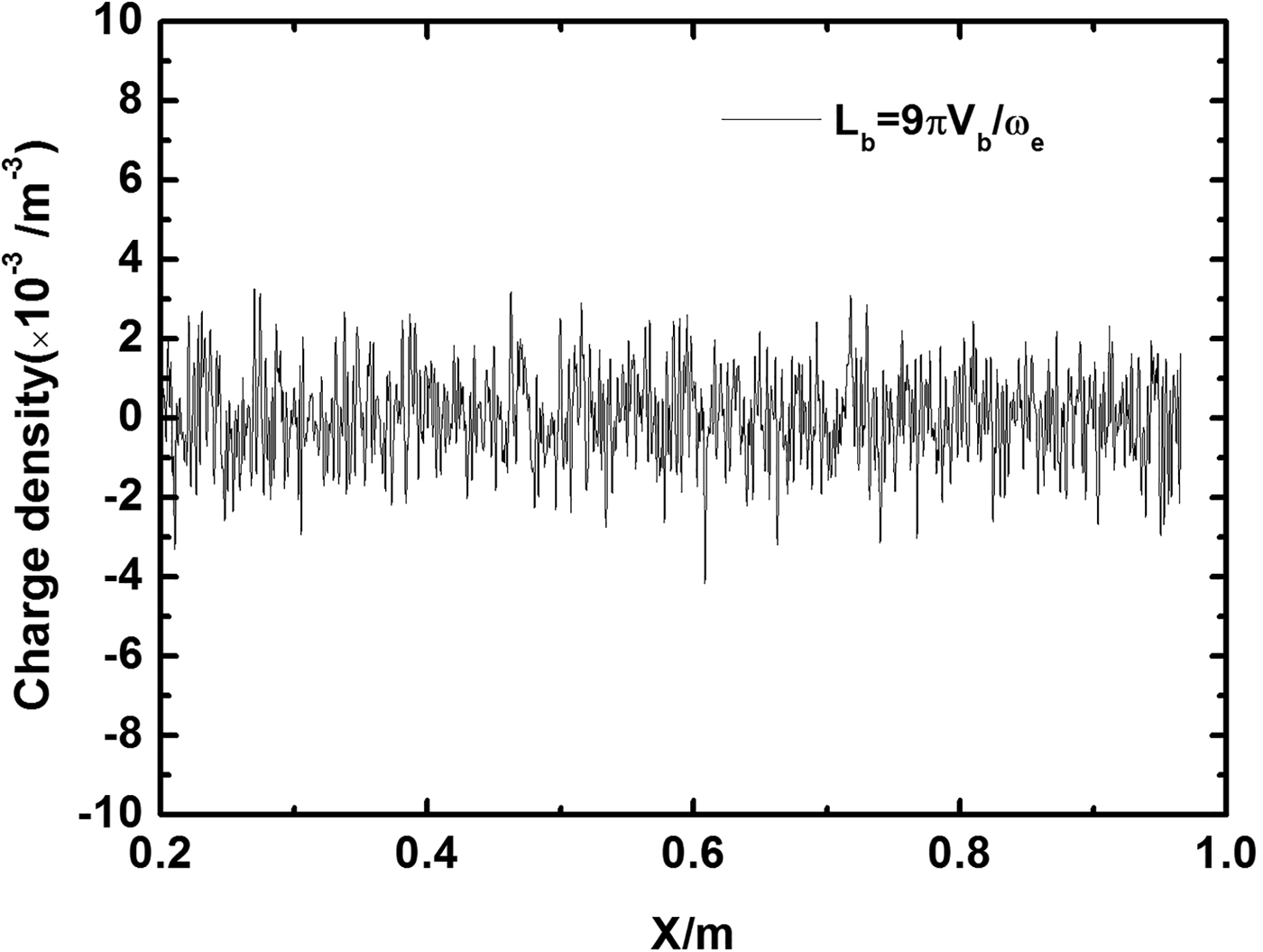
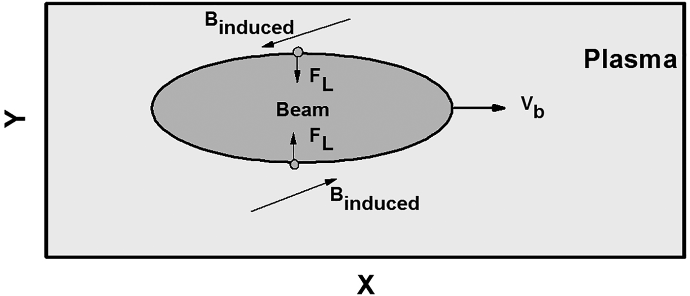
The propagation of the long proton beams is then investigated. Figure 3 shows the density of the proton beam (normalized by N e0) propagation in plasmas at time: (a) t = 1.48 ns, (b) t = 4.50 ns, and (c) t = 9.90 ns. The half-length L b is set as 9 πV b/ωe. The other parameters are the same with the short beam. It is found that in the process of the beam propagation, the beam with initial density n b0 = 0.5 n e0 is focused into n b0 = 0.6741 n e0, which implies that the plasma electrons make the beam focused. Figure 4 shows the charge density of the whole simulation box, including the beam protons, the plasma electrons, and plasma ions, at t = 9.90 ns, which corresponds that the position of the center of the beam is around x = 0.85 m. At this time, the density of the beam is about 0.6741 n e0 = 6.741 × 10¹⁷m−3. If the beam charge is not well neutralized, then there will be a peak of charge in the background plasma. However, the oscillation in Figure 4 is irregular and the order of the charge density is 10 − 3 m − 3, which is much smaller than the order of the beam density. Thus, it is concluded that the beam charge is well neutralized (100%). This effect makes the beam indiffuse. When the beam of positively charged particles moves through the plasmas, the accelerated plasma electrons bring two effects on the beam: neutralization the beam charge and neutralization the beam longitudinal current. Kaganovich et al. (Reference Kaganovich, Stvets and Startsev2001) have found that for a flat beam (R b <c/ωe), the longitudinal current of the beam is not completely neutralized. The unneutralized longitudinal current of the beam results in the toroidal magnetic field around the beam. The focusing phenomenon can be explained from the magnetic field. Figure 5 shows the induced magnetic field in the z-direction of the whole simulation box at t = 9.90 ns. It is found that there is toroidal magnetic field around the beam. The protons on the top experience the negative Lorentz force and the protons on the bottom experience the positive Lorentz force, which eventually lead to the focusing phenomenon, as shown in Figure 6.

Fig. 3. The density of the proton beam (normalized by N e0) with half-length L b = 9.0 πV b/ωe propagation in plasmas at time: (a) t = 1.48 ns, (b) t = 4.50 ns, and (c) t = 9.90 ns.

Fig. 4. The charge density of the whole simulation box at t = 9.90 ns.

Fig. 5. The induced magnetic field in the z-direction induced by the beam at t = 9.90 ns.

Fig. 6. The diagram of the focusing effect.
The propagation of the long proton beams with the different beam density profile is also simulated. The beam density profile N b is
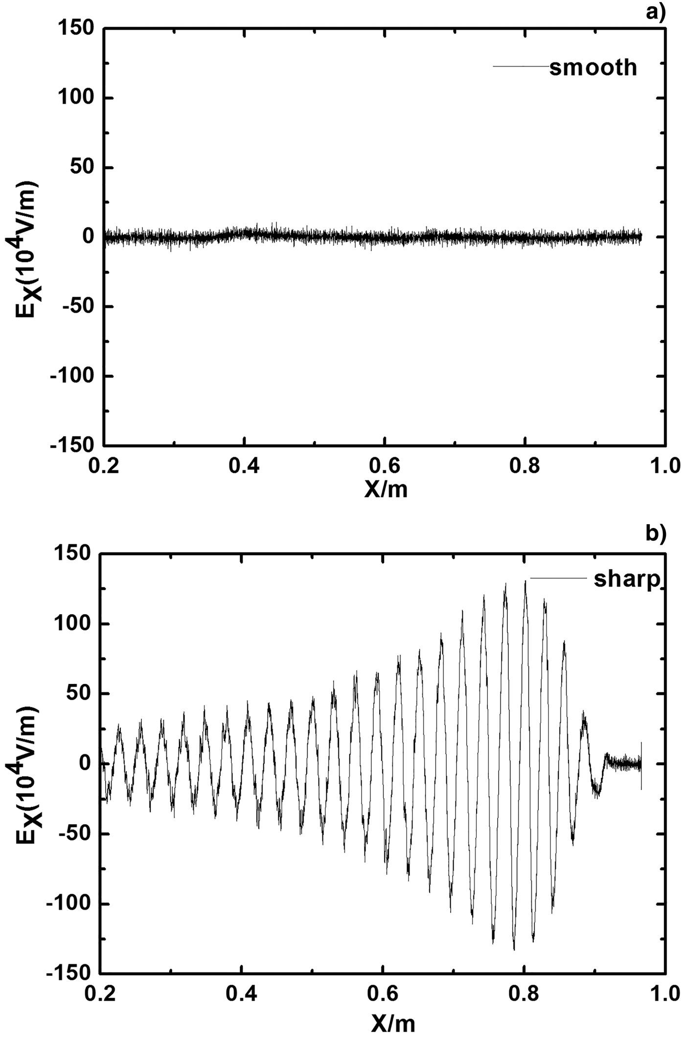
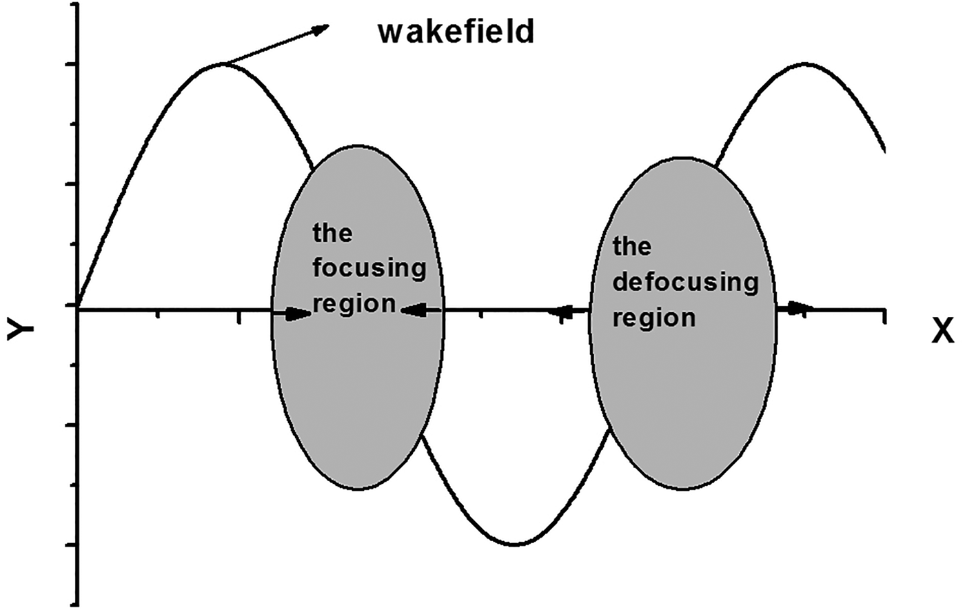
Compared with the above beam, this beam density profile rises steeply. Thus, this beam is called the sharp beam and the above beam is called the smooth beam. Except the beam density profile, the other parameters of the smooth beam and the sharp beam are the same. Figure 7 shows the density of the sharp proton beam (normalized by N e0) propagation in plasmas at time: (a) t = 1.48 ns, (b) t = 4.44 ns, and (c) t = 8.88 ns. Compared with Figure 3, it is found that: (1) for the sharp beam, the initial long proton beams is separated into many short ion pulses. The separation of these pulses S b is constant, and is roughly equal to 0.0302 m. This result corresponds well to the analytical estimation result (Hu et al., Reference Hu, Song, Zhao and Wang2013), which is the flight length of the beam during the plasma oscillation period 2 πV b/ωe. (2) The proton beam with initial density n b0 = 0.5 n e0 is focused into n b0 = 9.69 n e0, which is much higher than that for the smooth beam propagation in plasmas at the same time. These can be easily explained from the corresponding oscillation wakefield in the x-direction induced by the smooth beam and the sharp beam, as shown in Figure 8a and 8b, respectively. It is found that for the smooth proton beams, the wakefield is too weak to be recognized. The influence of the wakefield on beam protons is negligible. However, for the sharp proton beam, the damped plasma oscillations can be clearly seen behind the beam. The beam protons are accelerated and decelerated by the positive and negative wakefields, which produce the focusing and defocusing regions, and eventually lead to the period pulses. The detailed investigation is given in Figure 9. It is found that the focusing region is located in the region that the protons on the left experience the positive field and the protons on the right experience the negative field. The defocusing region is located in the region that the protons on the left and right experience the negative and positive fields, respectively.

Fig. 7. The density of the sharp proton beam (normalized by N e0) with half-length L b = 9.0 πV b/ωe propagation in plasmas at time: (a) t = 1.48 ns, (b) t = 4.44 ns, and (c) t = 8.88 ns.

Fig. 8. The wakefield in the x-direction induced by (a) the smooth beam and (b) the sharp beam at t = 8.88 ns.

Fig. 9. The focusing and defocusing model.
In the view of practical applications, these results imply that the smooth long beams can be used in the transport and propagating the beams, such as the design of the future ion accelerators based on the plasma technology. The sharp long beams can be used in the focusing beams and energy deposition, such as the heavy-ion-driven high-energy density matter and inertial confinement fusion (ICF).
3.3. Method to reduce the wakefied
In Section 3.2, it is found that the wakefield induced by the sharp beams influence the long transport. However, in practical applications, it is also necessary for the sharp beams to long-distance transmission. Thus, reducing the wakfield plays important roles in the propagation of the long proton beams.
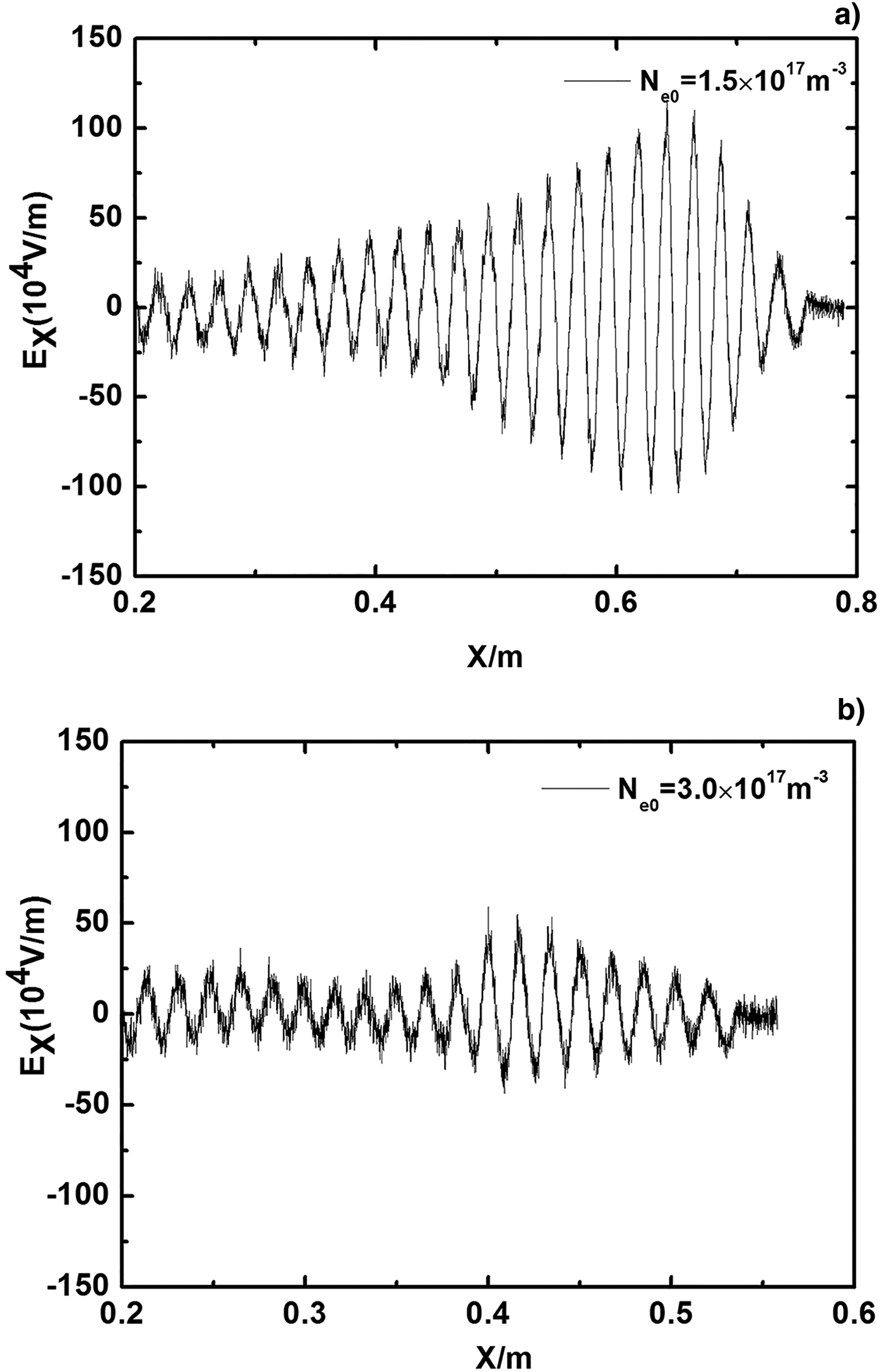
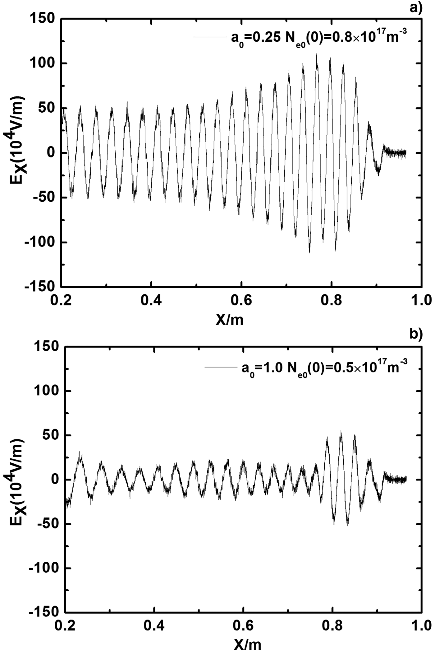
Figure 10 shows the oscillation wakefield in the x-direction induced by the sharp beam propagating in the plasmas with different plasma densities: (a) N e0 = 1.5 × 10¹⁷m−3 and (b) N e0 = 3.0 × 10¹⁷m−3 at t = 8.88 ns. In Figure 10a, the Debye shielding length is 6.069 × 10⁻⁵m, then L x = 0.789 m. In Figure 10b, the Debye shielding length is 4.291 × 10⁻⁵, and then L x = 0.558 m. Thus, the wakefield ends before 0.6 m for N e0 = 3.0 × 10¹⁷m−3, while it ends near 0.8 m for lower plasma density. It is found that as the plasma density increases, the amplitude of the wakefiled decreases linearly. Figure 11 shows the wakefield in the x-direction induced by the sharp beam propagating in the non-uniform plasma. The plasma density increases linearly in the beam propagation direction n e0(y) = n e0(0)(1 + a 0y/L y), where L y is the simulation length in the y-direction, a 0 is the plasma density gradient. In the simulation, L y is fixed and the plasma density in the right is fix to n e0(L y) = 1.0 × 10¹⁷m−3. Figure 11a shows the wakefield in the non-uniform plasma with a 0 = 0.25, that is, the plasma density on the left is n e0(0) = 0.8 × 10¹⁷m−3. Figure 11b shows the wakefield in the non-uniform plasma with a 0 = 1.0, that is, the plasma density on the left is n e0(0) = 0.5 × 10¹⁷m−3. It is found that as the plasma density gradient increases, the amplitude of the wakefiled decreases significantly. Thus, there are two effective ways to reduce the wakefield: (1) increasing the plasma density and (2) adopting the non-uniform plasmas.

Fig. 10. The wakefield in the x-direction induced by the sharp beam propagating in the plasmas with different plasma densities: (a) N e0 = 1.5 × 10¹⁷m−3 and (b) N e0 = 3.0 × 10¹⁷m−3 at t = 8.88 ns.

Fig. 11. The wakefield in the x-direction induced by the sharp beam propagating in the non-uniform plasma with different plasma density gradient: (a) a 0 = 0.25 and (b) a 0 = 1.0 at t = 8.88 ns.
4. CONCLUSIONS
In this paper, the propagation of a proton ion beam in hydrogen plasmas is studied using the 2D3 V EM PIC simulation. All the particles involved in the simulation, including the beam protons, plasma electrons, and plasma ions, are treated by the PIC method. Special attention is paid on the focusing effects of the long proton beam propagating in background plasmas.
For the beam propagation in plasmas, it is found that the charge neutralization condition is that the half-length of the beam L b is longer than πV b/ωe, where V b is the beam proton velocity and ωe is the plasma electron frequency. For the long-length beam, it is found that the smooth beam (with the small density gradient profile) and the sharp beam (with the large density gradient profile) are focused to high density. The density of the sharp beam is much bigger than that for the smooth beam propagating in plasmas at the same time. In addition, the sharp beam is modulated into many high density and periodic short beam pulses due to the wakefield induced by the beam. For the long-distance transmission of the sharp beams, there are two effective ways to reduce the wakefield: (1) increasing the plasma density and (2) adopting the non-uniform plasmas.
These results can bring an insight into the understanding of the interactions between the ion beam and plasmas. They would also provide useful information for the further theoretical and experimental works in this field. In view of practical applications, the study could be extended to applications in the heavy-ion-driven high-energy density physics and plasma lens. Our results show that the smooth long beams can be used in the transport and propagating beams and the sharp long beams can be used in the focusing beams and the energy deposition.
ACKNOWLEDGEMENTS
This work is supported by the National Natural Science Foundation of People's Republic of China (grant no. 11505261) and the National Magnetic Confinement Fusion Science Program of China (grant no. 2014GB104002).


