Introduction
The wireless communication system has received extensive attention and witnessed development since the U.S. Federal Communications Commission (FCC) designated the 3.1–10.6 GHz operation frequency for commercial applications [1]. As a key part of the ultra-wideband (UWB) system, UWB antennas and UWB filters are usually studied and designed as two separate devices [Reference Li, You, Yu, Li, Yang and Deng2]. Antennas are used to transmit or receive electromagnetic waves, so in the design process, more attention is paid to its structure size [Reference Nikolaou and Abbasi3, Reference Singhal and Singh4], impedance bandwidth [Reference Manohar, Kshetrimayum and Gogoi5, Reference Emadian and Ahmadi-Shokouh6], and radiation patterns [Reference Sun, Wen, Jin, Wang and Huang7]. The suppression of out-of-band interference signals is usually achieved by filters. However, the use of a series bandpass filter to suppress out-of-band interference signals has problems such as matching loss, large size, and difficulty in layout [Reference Li, You, Yu, Li, Yang and Deng2, Reference Wong, Huang, Mao, Chen and Chu8]. Therefore, UWB antennas with filtering function make great significance in suppressing out-of-band signals and improving receiver performance.
Some antennas with filtering characteristics have been reported in [Reference Djaiz, Habib, Nedil and Denidni9–Reference Sahu, Singh, Meshram and Singh12]. In [Reference Djaiz, Habib, Nedil and Denidni9], by designing the radiation patch antenna and filter together and matched with 50 Ω, an excellent stop band at 5.8 GHz is obtained. In these techniques, several filtering UWB antennas with integrated bandpass filters have also been demonstrated [Reference Kumar, Dutt and Parihar Manoj10–Reference Sahu, Singh, Meshram and Singh12], such as designing a UWB bandpass filter coupling to the circular patch [Reference Kumar, Dutt and Parihar Manoj10], using a flower-shaped UWB bandpass filter instead of the 50 Ω microstrip feeding line [Reference Ranjan, Raj, Upadhyay, Tripathi and Tripathi11], and inserting a super-compact bandpass filter [Reference Kumar, Dutt and Parihar Manoj10]. Good filtering function and band-edge selectivity are obtained by these techniques. Although the design of filtering antennas can reduce the dimensions of RF front end, it is difficult to realize miniaturization because of the complex structure of microstrip feeding line with filtering characteristics and the large structure of monopole antennas. Therefore, compared with most traditional antennas [Reference Nikolaou and Abbasi3–Reference Wong, Huang, Mao, Chen and Chu8], these antennas are still larger in size. The size of these proposed designs is 53 mm × 42 mm [Reference Kumar, Dutt and Parihar Manoj10], 32 mm × 27 mm [Reference Ranjan, Raj, Upadhyay, Tripathi and Tripathi11], and 36 mm × 21 mm [Reference Sahu, Singh, Meshram and Singh12], respectively.
In [Reference Yang, Xi, Zhao, Wang and Shi13], a modified microstrip-fed stepped slot antenna with enhanced band-edge selectivity is presented. The stepped impedance feeding line as a lowpass filter plays an important role in improving the selectivity of upper passband. However, our study indicates that the modified fed line has an adverse influence on the radiation efficiency, and the radiation efficiency of the previous design was about 80%. This may be due to the fact that there is a certain insertion loss and the coupling ability of the stepped impedance microstrip line is weakened compared with the traditional 50 Ω feeding line. In addition, the in-band impedance characteristics of slot antennas are not ideal, and the in-band impedance characteristics of similar slot antennas reported in [Reference Chu, Mao and Zhu14–Reference Bekasiewicz and Koziel17] are also not ideal. It is found that the reflection coefficients of these designs are only −10 dB, which are still need to be improved. Although a slot antenna has a simple structure, but the resonance mode is also relatively simple, it is difficult to obtain an ideal in-band impedance characteristic by simply optimizing the stepped slot or the microstrip feeding line.
In this study, a new compact slot antenna with good band-edge selectivity and in-band impedance characteristics using a modified radiation slot is presented. The modified radiation slot is composed of a step slot and three pairs of defected ground structures (DGS). The square dumbbell DGSs are obtained by etching defected structures in the bottom of the ground plane, which can generate additional resonant modes in some frequencies and suppress the unwanted harmonics. In addition, by introducing an additional open slot parallel to the modified radiation slot, the low-frequency current paths are extended and a new reflection zero is generated. Then, the bandwidth and selectivity of the lower frequencies are improved. To verify the proposed design, the filtering antenna with a modified radiation slot has been fabricated and designed. Research found that the proposed design exhibits good band-edge selectivity (BW−3 dB/BW−10 dB = 1.05), in-band impedance matching (−13.5 dB), and radiation efficiency (90%). In addition, the size of the antenna is smaller than the reference antenna [Reference Yang, Xi, Zhao, Wang and Shi13–Reference Gopikrishna, Das Krishna, Aanandan, Mohanan and Vasudevan16]. Different than references [Reference Yang, Xi, Zhao, Wang and Shi13–Reference Gopikrishna, Das Krishna, Aanandan, Mohanan and Vasudevan16], the radiation slot of the antenna is composed of stepped slot and DGS, which makes the antenna not only change the length of slot to change the resonant frequency, the resonant frequency can also be adjusted by adjusting the parameters of DGS.
Antenna design
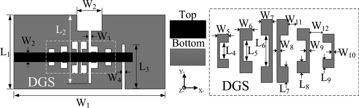
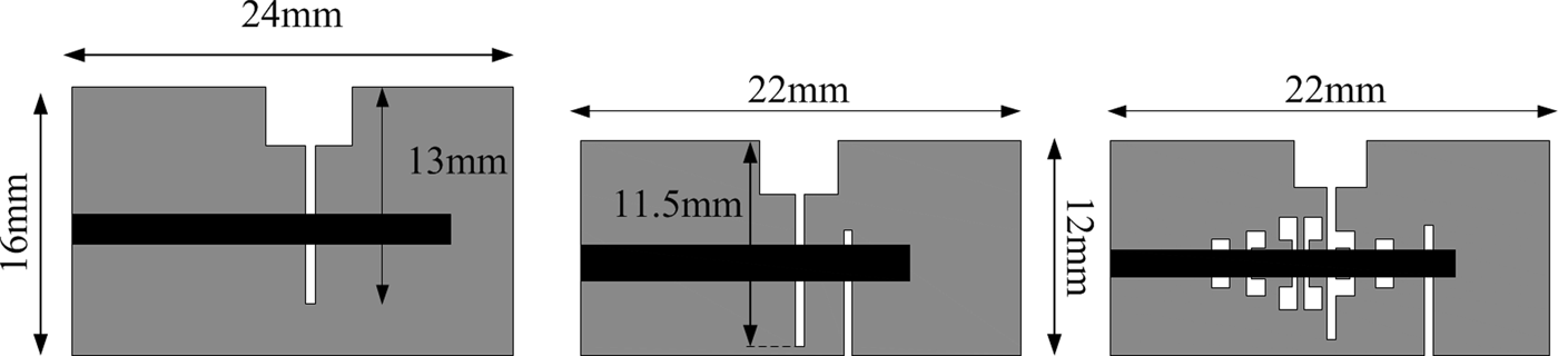
Figure 1 shows the geometry of the proposed antenna and schematic of the DGS. The prototype of the proposed design is shown in Fig. 2(a), which is a microstrip-fed stepped slot antenna printed on the substrate with a relative dielectric of 2.2 and thickness of 0.787. The simulated reflection coefficient and radiation efficiency of type-I antenna is illustrated in Fig. 3(a). Same as other slot antennas presented in [Reference Chu, Mao and Zhu14–Reference Bekasiewicz and Koziel17], the maximum value of the reflection coefficient of type-I antenna is −10 dB, which is not ideal for UWB applications. At the same time, the simulation bandwidth of type-I antenna is from 3.75 to 15 GHz. The start frequency of type-I antenna is larger than 3.1 GHz which does not match the lower start frequency of UWB system. Furthermore, the selectivity of type-I antenna is very poor. Type-II antenna in Fig. 2(b) is an improvement of type-I antenna, which has smaller size and wider bandwidth than type-I antenna. The additional opening slot close to the stepped slot can effectively extend the low-frequency current path, thus improving the bandwidth of the low frequency and reducing the physical size of the antenna [Reference Yang, Xi, Zhao, Wang and Shi13]. As shown in the lower band of reflection coefficient in Fig. 3(a), the initial frequency of type-II antenna changes from 3.75 to 3.1 GHz after introducing narrowband slots and the sideband selection characteristics of the low frequency are also improved.

Fig. 1. Geometry of the proposed antenna with a modified radiation slot.

Fig. 2. Design process of the filtering UWB antenna: (a) type-I, (b) type-II, and (c) type-III.
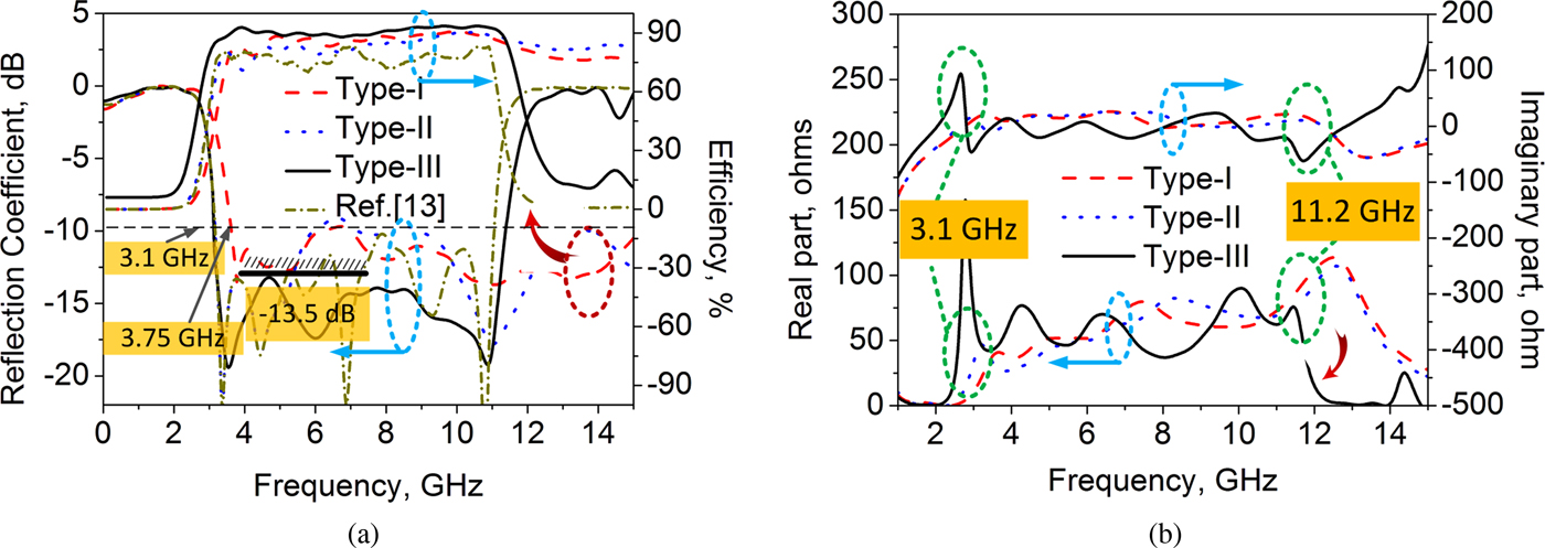
In order to further improve the shape roll-off of the proposed design, especially at high frequencies, a modified feeding line with lowpass function is proposed in our previous work [Reference Yang, Xi, Zhao, Wang and Shi13]. Good filtering characteristics are obtained in the results of reflection coefficient and radiation efficiency after using stepped impedance microstrip fed line. Nevertheless, the impedance characteristics in the passband of the reference antenna [Reference Yang, Xi, Zhao, Wang and Shi13] are still not improved compared with type-I and type-II antennas. In addition, the reference antenna has a radiation efficiency of approximately 80%, which is 8% lower than the antenna proposed in Fig. 2(a) and 2(b). This may be due to the fact that the coupling between the stepped impedance microstrip line and the slot is weaker and the loss is greater than that of the traditional 50 transmission line. In this paper, a new compact filtering UWB antenna with good band-edge selectivity and in-band impedance characteristics using a modified radiation slot is proposed. The modified radiation slot is composed of a stepped slot and three pairs of DGSs. The well designed DGSs are achieved by etching defected structures in the ground plane as shown in Fig. 2(c), which can produce additional resonant modes in some frequencies and provides a good roll-off at higher frequencies. The solid black lines in Fig. 3(a) represent the reflection coefficient and radiation efficiency of the final design, respectively. It can be clearly seen that with the improved stepped slot, the sideband selection characteristics and the in-band impedance characteristics of type-III antenna significantly improved. The maximum amplitude of reflection coefficient of the final design is −13.5 dB, and only in 4–5 GHz band it is larger than −15 dB. Compared with other reported slot antennas [Reference Yang, Xi, Zhao, Wang and Shi13–Reference Bekasiewicz and Koziel17], the in-band impedances are obviously improved. Due to the good in-band impedance characteristics of type-III antenna, the radiation efficiency of type-III antenna is greater than that of referenced antenna in [Reference Yang, Xi, Zhao, Wang and Shi13]. It is also observed that the size of type-III antenna is the smallest. This is because the additional slot in Fig. 2(b) antenna and DGS in Fig. 2(c) antenna can provide additional resonance and extend the current path, which is beneficial to the miniaturization of the antenna. Figure 3(b) illustrates the changes of input impedance of antennas indicated in Fig. 2. Research found that the real and imaginary part of the proposed design drop sharply at the lower and upper frequencies after adding the additional opening slot and DGS.
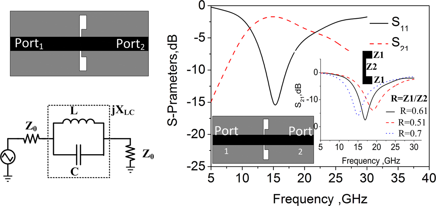
DGS unit is obtained by etching defected pattern on the bottom of the substrate. The LC equivalent circuit and simulated S-parameters are shown in Fig. 4. A microstrip line with a DGS unit can produce transmission zeros and excellent rejected bands in some certain frequencies, which can be applied to suppress the higher order harmonics and keep the selectivity sharp. Thus, the DGS has been applied to design microwave circuits to obtain excellent stopband characteristics [Reference Liu, Li and Sun18, Reference Song, Yang and Geyi19]. The DGS unit consists of narrow and wide etched areas in backside metallic ground plane namely Z 1 and Z 2, as seen in the bottom right corner of Fig. 4. Therefore, the resonant frequency can be controlled by adjusting the ratio of Z 1 to Z 2. This is because when Z 1 and Z 2 change, their corresponding inductance and capacitance also change. Thus, by designing three pairs of DGS with different dimensions in series, a wide stop band is obtained as shown in Fig. 5. The effect of physical dimensions of the DGS can be explained based on the circuit analysis theory. In Fig. 4, we have illustrated that the LC equivalent circuit can represent DGS unit, so a low pass filter with a wide stopband is obtained by serializing multiple DGSs, as shown in Fig. 5. To explain the attenuation pole and cut-off characteristics of the DGS, the equivalent circuit is introduced. The DGS unit dimensions could be extracted from the prototype element value is provided from the equivalent circuit. The inductance and capacitance values of the circuit for the equivalent circuit can be calculated by the prototype of the Butterworth-type lowpass response, which has −3 dB cut-off frequency at 13 GHz. The element value of the equivalent can be expressed as follows:
 $$X_{LC}\, = \,\left[ {\omega_0C\left( {\displaystyle{{\omega_0} \over \omega} \,-\,\displaystyle{\omega \over {\omega_0}}} \right)} \right]^{-1}$$
where ω 0 is the resonant angular frequency of the DGS unit. For the first-order single-pole Butterworth low-pass prototype filter, its series inductance can be expressed as:
 $$X_L\, = \,\omega L\, = \,\omega {\rm ^{\prime}}Z_0g{\rm ^{\prime}}$$
where ω′ is the normalized angular frequency, Z 0 is the characteristic impedance of microstrip transmission line, and g′ is the prototype parameter of the Butterworth low pass filter. At a certain frequency, the cut-off frequency of the lowpass filter can be expressed as:
 $$ {X_{LC}} \vert _{\omega = \omega _C} = {X_L} \vert _{\omega {\rm ^{\prime}} = 1}$$
Fig. 4. Equivalent circuit of the proposed DGS circuit unit and the corresponding reflection coefficients.
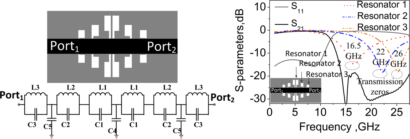
Fig. 5. Equivalent circuit of the three pairs of DGSs and the corresponding S-parameters.
From equations (1), (2), and (3) equivalent C and L are calculated as given in (4) and (5):
 $$C = \displaystyle{{\omega _C} \over {gZ_0}}\displaystyle{1 \over {\omega _0^2 -\omega _C^2}} $$
 $$L = \displaystyle{1 \over {\omega _0^2 C}} = \displaystyle{1 \over {4\pi ^2f_0^2 C}}$$
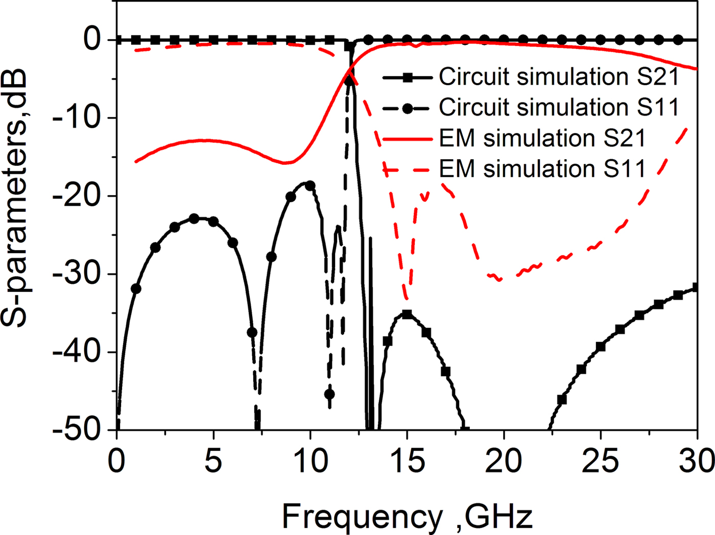
where f 0 is the frequency of the attenuation pole location and C is the extracted series capacitance value. The parallel capacitance in a lumped lowpass filter can be realized by using the parallel open stub. Then the calculated parameters for the lowpass filter are L 1 = 0.178 nH, C 1 = 0.832 pF, L 2 = 0.3 nH, C 2 = 0.478 pF, L 3 = 0.56 nH, C 3 = 0.114 pF, C 4 = 0.194 pF, and C 5 = 0.24 pF. Figure 6 illustrates the comparison between the equivalent circuit and electromagnetic (EM) simulation of the lowpass filter. Research found that the simulated S-parameters of the proposed DGS are matched to the equivalent circuit. The validity of the modeling method for the proposed DGS unit section and the design method for the low-pass filter is verified by experiments. The optimum values of the optimized design are simulated using the CST microwave studio simulator and shown in Table 1.

Fig. 6. Circuit simulation and EM simulation of the lowpass filter.
Table 1. Dimensions of the proposed design

Experimental results
To verify the final design, the proposed antenna is manufactured according to the dimensions provided in Table 1. Both the frequency domain and time domain characteristics are analyzed in this section.
Frequency domain analysis
The simulated and measured reflection coefficients of the filtering antenna with the modified radiation slot are shown in Fig. 7. It is found that the measured results agree well with the simulations. The measured −10 dB operating band is from 3.1 to 11.2 GHz. The measured shape factor (BW−3 dB/BW−10 dB) of the proposed design is 1.05, which shows good band-edge selectivity in the lower and upper bands. The maximum magnitude of reflection coefficient is −13.5 dB and there are two reflection zeros in the upper and lower sidebands which is beneficial to the improvement of sideband selectivity. Compared with other slot antennas [Reference Yang, Xi, Zhao, Wang and Shi13–Reference Bekasiewicz and Koziel17], this antenna exhibits better in-band impedance characteristics.
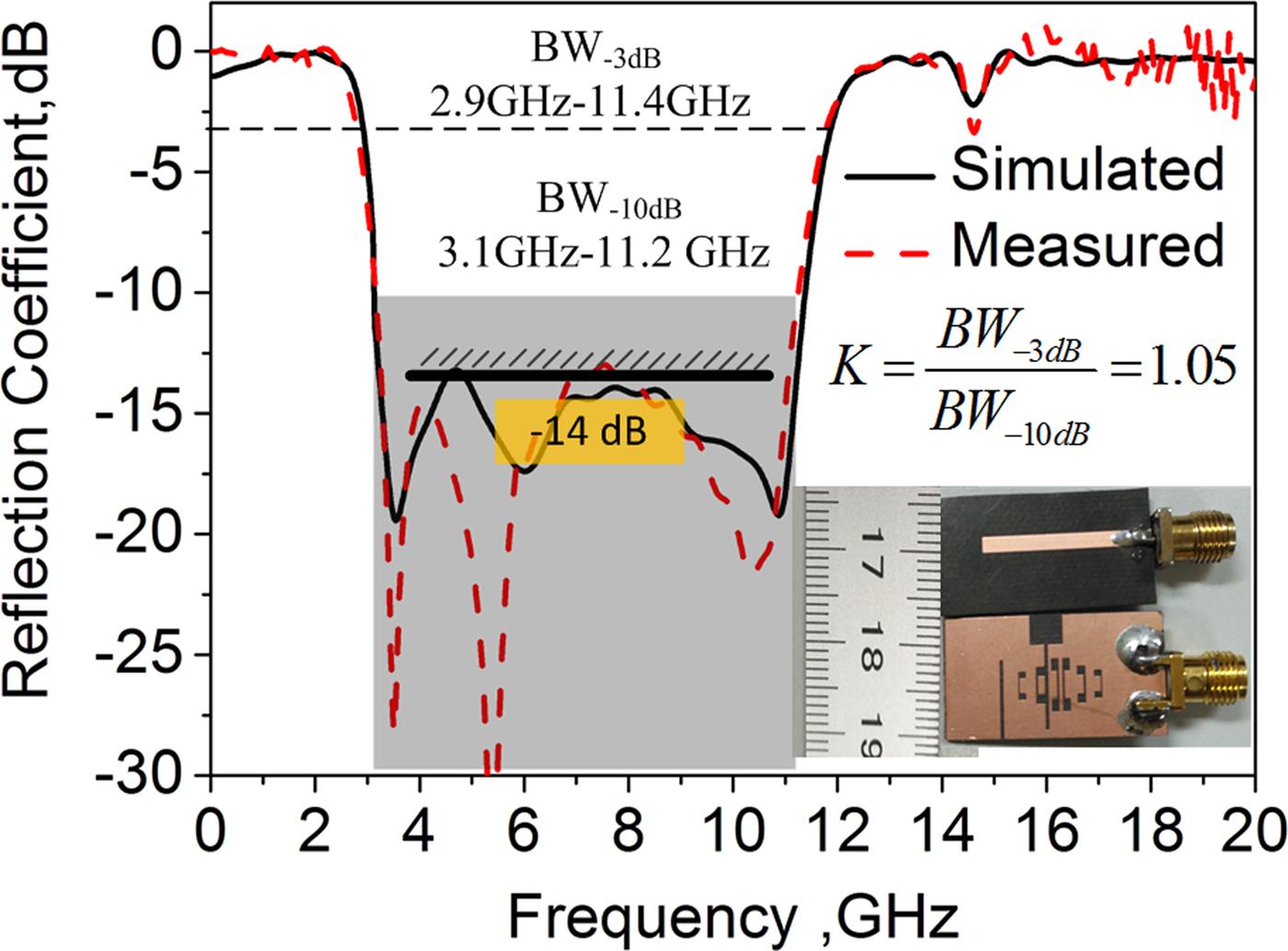
Fig. 7. Simulated and measured reflection coefficient of the proposed design.
Good bandpass filtering characteristics can also be illustrated through the gain and efficiency performance, as seen in Fig. 8. The maximum amplitude of gain and radiation efficiency in the passband of the proposed design is 4.5 dBi and 90%, respectively. Compared with the antenna in [Reference Yang, Xi, Zhao, Wang and Shi13], the radiation efficiency and gain have been improved. Therefore, the proposed slot antenna with DGS is a better choice than the reference antenna [Reference Yang, Xi, Zhao, Wang and Shi13]. It is because the proposed antenna not only has a good band-edge selectivity, but also performs well in in-band impedance and radiation efficiency.
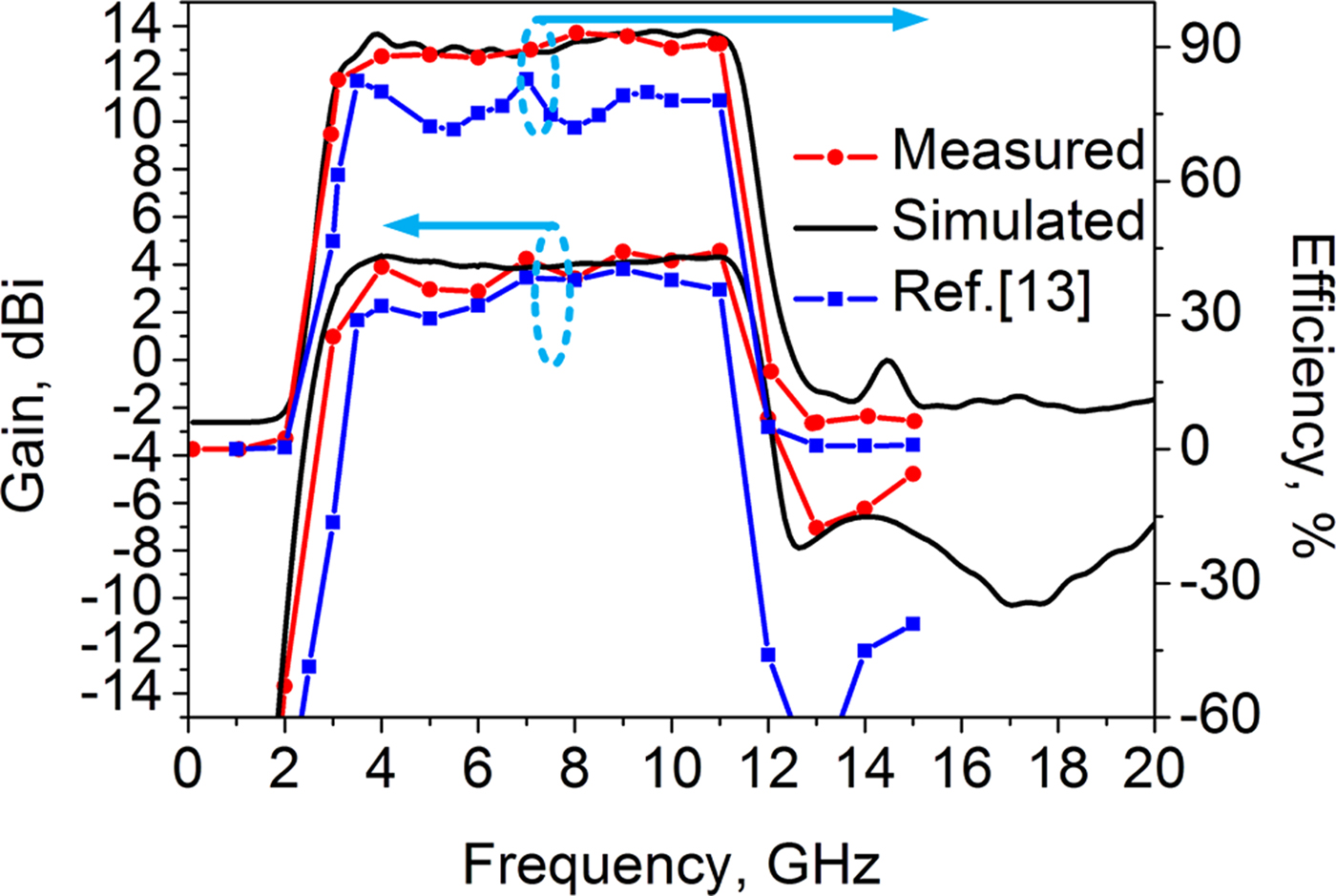
Fig. 8. Simulated and measured efficiencies and gains of proposed design and referenced antenna in [Reference Yang, Xi, Zhao, Wang and Shi13].
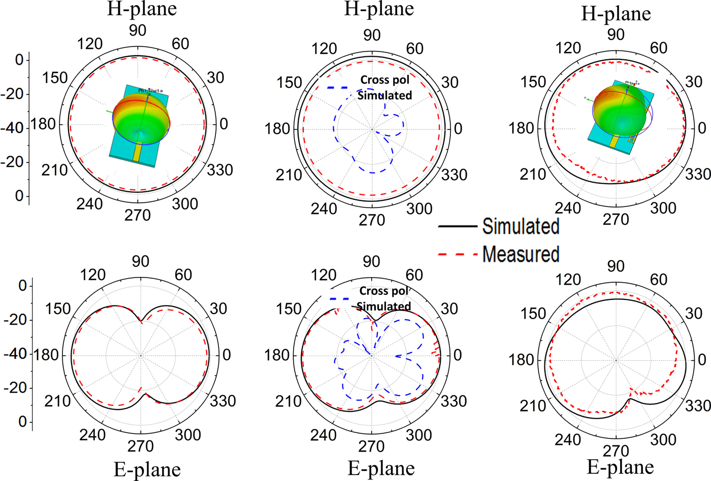
Figure 9 plots respectively, the simulated and measured radiation patterns in E-plane and H-plane at 3.1, 6, and 10 GHz. We can see that the measured results agree well with the simulations and illustrate a low cross-polarization level at 6 GHz. This study also presents a set of 3D radiation patterns in order to show a better picture of the radiation effect. It can be seen that with the increase of frequency, the directional pattern increases in the opening direction of the slot, and the pattern shows certain directional radiation characteristics, especially at 10 GHz. This is because as the frequency increases, the current is concentrated more at the edge of the modified radiation slot.

Fig. 9. Simulated and measured radiation patterns of the proposed design: (a) 3.1 GHz, (b) 6 GHz, and (c) 10 GHz.
Table 2 shows the comparisons of the characteristics between the proposed design and some other competitive reported antennas. As can be seen from Table 2, the proposed antenna and the previous design [Reference Yang, Xi, Zhao, Wang and Shi13] have advantages in size and shape factor compared with antennas reported in [Reference Wong, Huang, Mao, Chen and Chu8, Reference Ranjan, Raj, Upadhyay, Tripathi and Tripathi11, Reference Sahu, Singh, Meshram and Singh12]. In addition, the proposed antenna also has a good performance in the passband impedance and radiation efficiency.
Table 2. Comparison of the characteristics with some previous designs

Time domain analysis
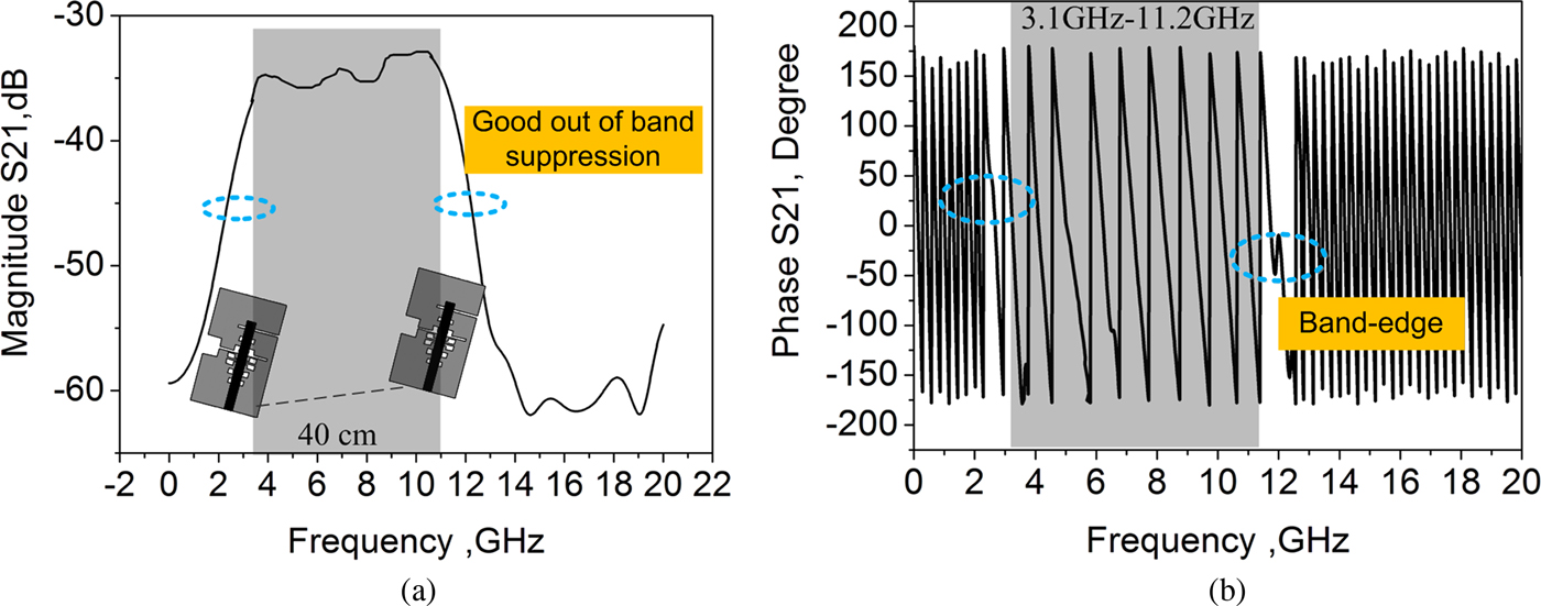
UWB antennas are designed to send or receive time-domain pulse signals, so it is necessary for the antenna to have a good time domain performance in the passband. To verify the proposed design performance in the time domain, the group delay, transfer functions (magnitude S 21 and phase S 21), and impulse response are discussed. Two same antennas are applied to transmit and receive signals, which are placed in a face-to-face position with a space of 40 cm.
Figure 10 illustrates the simulated and measured results of group delay with two identical filtering antennas at a distance of 40 cm. It is found that both the simulated and measured group delay of the proposed design in the passband approximates to 1.3 ns with little in-band fluctuations (<0.2 ns). Figure 11 shows the transfer functions of two identical filtering antennas placed in face-to-face. It can be seen in Fig. 11(a) that identical antennas exhibits approximately flat magnitude for S 21 (−35 dB) in operating frequencies and good frequency rejection characteristics in the band-edge (exhibits about 30 dB band-edge rejection). It is also noticed that the proposed design exhibits a good linear variation of phase in the passband, except for in the band-edge. All these simulated results indicate that the proposed design exhibits a good performance in the passband and good filtering characteristics out-of-band.
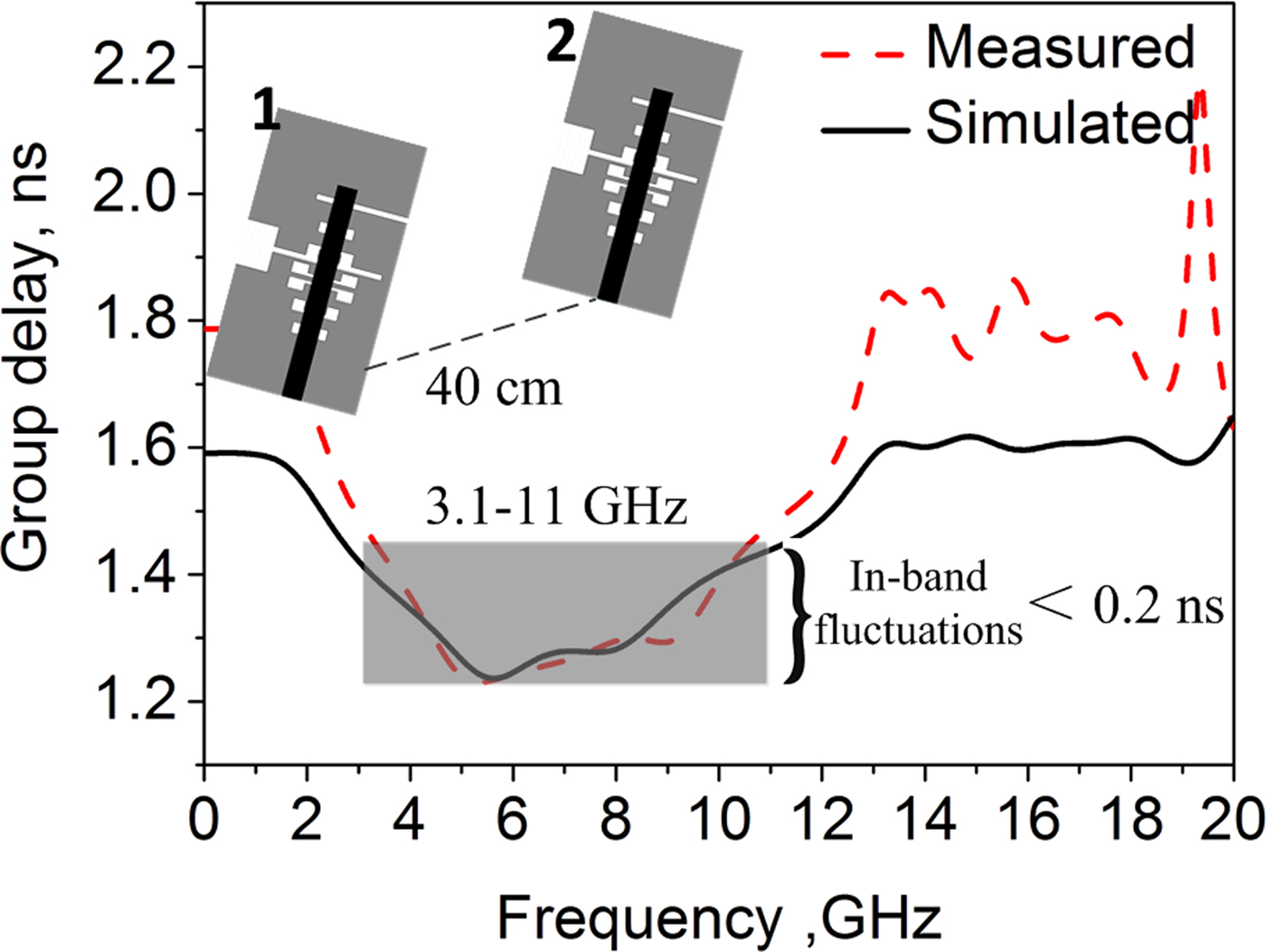
Fig. 10. Group delay of the design with a distance of 40 cm.

Fig. 11. Simulated transfer functions of the filtering antenna: (a) magnitude S 21 and (b) phase S 21.
The input pulse and received waveforms of the proposed design are illustrated in Fig. 12. To meet the requirements of the FCC for UWB signal spectrum and mitigate the influence of bandwidth and impedance mismatch on UWB signal distortion, an input UWB signal presented in [Reference Telzhensky and Leviatan20] (a fifth-order derivative of the Gaussian pulse) is applied to excite the filtering slot antenna. From Fig. 12, it can be observed that there is slight ringing distortion at the end receiving signal in the case of face-to-face and side-to-side. It is mainly due to the mismatch between connectors and the loss during transmission. In addition, the waveform and amplitude of the received signal are very close in both cases. The good performance of the proposed design in the frequency domain and time domain demonstrates that the well-designed filtering antenna could be a good choice for UWB application.
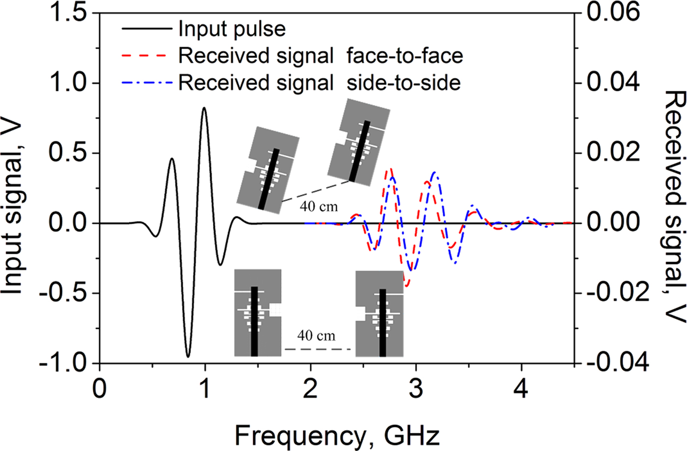
Fig. 12. Input and received pulses.
Conclusion
In this study, a new compact highly selective UWB slot antenna with a modified radiation slot using DGS has been presented to achieve good bandpass filtering function and in-band impedance characteristics. By etching the DGS and adding an additional opening slot close to the modified stepped slot, both the upper and lower band-edge selectivity of the proposed design are enhanced, and the unwanted interference signals out-of-band can be effectively suppressed. Additionally, the measured results agreed well with the simulation and both the simulated and measured reflection coefficient and gain of the design show the good filtering characteristics. What's more, it is of great significance to study the filtering characteristics of slot antennas for the further improvement and development of slot antennas in application.
Acknowledgement
This work was supported in part by the National Defense Pre-Research Foundation of China (6140450010302), the National Natural Science Foundation of China under Grant 61701398, the Key Research and Development Plan of Shaanxi Province (2017ZDXM-GY-117), and the Doctoral Innovation Fund of Xi'an University of Technology.
 Hailong Yang received his B.S. in communicating engineering from Heze University, Heze, China, in 2012 and his M.S. degree in communicating engineering from the Xi'an University of Technology, Xi'an, China, in 2015. He is currently working toward his Ph.D. degree at the Xi'an University of Technology, Xi'an, China. His recent research interests include ultra-wideband antennas, reconfigurable antennas, and ultra-wideband filters.
 Xiaoli Xi (M'2010) received her B.S. degree in Applied Physics from the University of Defense Technology, Changsha, China, in 1990 and her M.S. degree in Biomedical Engineering from Fourth Military Medical University, Xi'an, China, in 1998, and her Ph.D. degree in electrical engineering from Xi'an Jiaotong University, Xi'an, China, in 2004. She is currently a Professor at the Department of Electric Engineering, Xi'an University of Technology, Xi'an, China. Her recent research interests include wave propagation, antenna design, and communication signal processing.
 Lili Wang received her B.S. in electromagnetic field and microwave technology from the Beijing University of Post and Telecommunications, Beijing, China, in 1990 and her M.S. degree in electrical engineering from the Xi'an University of Technology, Xi'an, China, in 2004. She is now an Adjunct Professor at the Department of Electric Engineering, Xi'an University of Technology, Xi'an, China. Her recent research interests include wave propagation and antenna design.
 Yuchen Zhao received his B.S., M.S., and Ph.D. degrees in electronic science and technology from Northwestern Polytechnical University, Xi'an, China, in 2007, 2010, and 2014, respectively. He joined the faculty of Electronic Engineering Department, Xi'an University of Technology in 2014. His research interests include wave propagation and effective medium theories.
 Xiao-Min Shi received her B.S., M.S., and Ph.D. degrees from the Xi'an University of Technology, Xi'an, China, in 2010, 2013, and 2017, respectively. She joined the Communication Engineering Department, Xi'an Shiyou University, Xi'an in 2017. Her research interests include analysis and design of microwave filters and RF passive circuits.