1.0 INTRODUCTION
Historically, system safety analysis was primarily based on system schematics(1). Although this approach provided an overview of the different systems in the aircraft, it could not identify any system physical installation implications that might adversely affect the independence between items. Therefore, it was necessary to define an analysis to consider the installation conditions of respective systems/items and the effects that they may have on each other within the same zone. This analysis is known as the Zonal Safety Analysis (ZSA)(1).
ZSA constitutes part of the safety assessment process of Aerospace Recommended Practice 4761 (ARP4761) – ‘Guidelines and Methods for Conducting the Safety Assessment Process on Civil Airborne Systems and Equipment’, which comprises the generation of requirements, as well as verification to support aircraft development activities(2). Although ZSA may be performed at any design stage, it would be most cost-effective to do it during preliminary design because of the opportunity for influence on system design and architecture(1).
However, the ZSA methodology provided in ARP4761 is more suitable for the detailed design stage where the detailed functions, architectures and requirements have become available for analysis. These are inputs such as installation drawings, component Failure Modes and Effects Analysis (FMEA) results and Preliminary System Safety Assessments (PSSAs). These do not have enough detail during the preliminary design stage. Hence, there is a need to develop a ZSA methodology that is better suited to guide aircraft designers during preliminary design.
This paper outlines the development of a methodology, hereafter referred to as the Preliminary Zonal Safety Analysis (PZSA). It is to be used to perform ZSAs during preliminary design, with a focus on advanced aircraft technologies.
The development process was to start with a literature review, including relevant information on the aircraft design(Reference Raymer3) and safety assessment processes(1,2) . The existing ZSA was to be analysed to understand its objectives, as well as the inputs and outputs required. Documents relating to aircraft zone partitioning(4) and risk assessment(5), as well as any related past theses(Reference Yu6), were also to be studied.
The next objective was to develop an initial PZSA Methodology for Preliminary Aircraft Design, based on any limitations of the existing method. This was then to be examined by using a relevant case study. The NASA N3-X project was chosen for this, as the initial systems and structures design and architecture layout data were available to the authors.
The initial PZSA Methodology was then to be used on the selected aircraft. Zone partitioning was to be performed, with a focus on the aft fuselage where the advanced technologies were located i.e. fuel cell and cryogenic refrigeration systems. The design and installation drawings were then to be analysed, and the systems/items located within the zones of interest were to be identified. After understanding the intrinsic hazards, a list of system/component external failure modes was to be developed. At the same time, the design and installation guidelines were to be consolidated. A zonal safety inspection was then to be conducted using these two lists as a guide and any deviations found from a risk assessment.
Appropriate follow-up actions were to be recommended, such as modifications to design or maintenance practices. Issues encountered during the case study were to be recorded, discussed, and used to refine the initial PZSA Methodology.
2.0 ANALYSIS OF THE INITIAL ZSA PROCESS
The ZSA methodology stated in ARP4761 was analysed with the objective of developing one that is better suited for preliminary aircraft design. Figure 1 shows this process.

Figure 1. Zonal safety analysis process (ARP4761)(1).
The original ZSA methodology described in ARP4761 was found to be more suitable for detailed aircraft design. For example, it requires certain inputs such as the ‘considerations from PSSA’ and ‘system PSSAs’ which are only available at the end of preliminary design or the beginning of detail design. These inputs are not available to the aircraft designer during preliminary design.
Another example that suggests the original methodology is better suited for detail aircraft design is the identification of outputs such as ‘modifications’ and ‘effects considered in relevant System Safety Assessments (SSAs)’. These are actions taken at the final design stage.
In addition, the original ZSA methodology does not provide any references or information sources to obtain the ‘experience’ and ‘maintenance and operational hazards’ inputs. Hence, it may be difficult for an inexperienced aircraft designer to use the methodology meaningfully. It would be beneficial to include some references that provide the relevant industry knowledge e.g. Society of Automotive Engineers (SAE) Aerospace Standards (AS) to act as inputs to ‘experience’ and ‘maintenance and operational hazards’.
The original methodology also assumes that all components have already been designed and the relevant information is available to develop the ‘list of component external failure modes’. However, this is not the case during the preliminary design stage where the system architecture is being developed and components are being designed. It would only be possible to develop a list of external failure modes at the system level instead of the component level during preliminary design.
Finally, the methodology does not specify a mechanism to perform risk assessments of zonal safety inspection findings. After performing the zonal safety inspection, it is important to carry out a proper assessment of non-conformances to determine their safety criticality so that the appropriate corrective actions can be taken. A systematic approach such as the risk assessment matrix stated in ARP5151 could be adopted to perform a qualitative risk assessment.
Based on the above analysis, changes (highlighted in green) were made to the ZSA methodology for it to be more suitable for preliminary aircraft design (see Fig. 2).
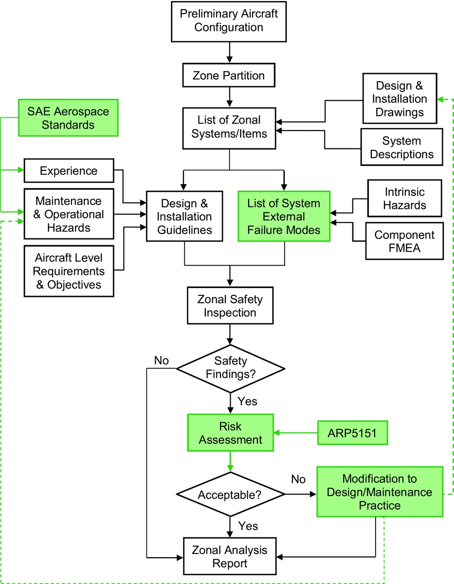
Figure 2. Proposed PZSA methodology for preliminary design.
The next step is to test and verify the methodology by applying it on an aircraft design.
3.0 CASE STUDY AIRCRAFT
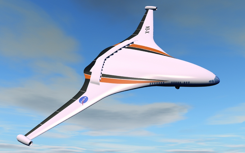
The aircraft selected to be the case study for this research was the NASA N3-X (see Fig. 3). Since the N3-X systems design and architecture layout had been completed (which is reflective of a preliminary design), it would be suitable to apply the proposed PZSA methodology on this aircraft. An additional benefit was that the authors were involved in the group design project and had access to the aircraft's systems and structure designs.

Figure 3. NASA N3-X(Reference Chen7).
The NASA N3-X has a unique hybrid wing body (HWB) configuration. This configuration achieves a much higher lift-to-drag ratio compared to conventional-shaped aircraft, thus achieving significant savings in fuel burn, aircraft weight and required thrust. The aircraft design also incorporates advanced technologies such as the turbo-electric distributed propulsion (TeDP) and cryogenic refrigeration systems. The TeDP system comprises 2 turboshaft engines and 14 electric fans. Superconducting generators are driven by the engines and power is transmitted to power inverters via superconducting transmission lines. Then, the power is transmitted to the superconducting fan motors which drive the electric fans permitting boundary layer ingestion (BLI), thus providing aerodynamic benefits. The advantage of using superconducting material is that it allows for high power efficiency, but the system has to be operated at low critical temperatures. Therefore, cryogenic refrigeration is used, which comes in the form of liquid hydrogen (LH2) or cryocoolers which can achieve very low temperatures of between 20K and 65K(Reference Lei9).
The NASA N3-X aircraft is required to have a similar passenger seat capacity and payload range compared to its competitors i.e. accommodation capacity of 300 passengers; range of 7,500 nm with a payload of 53,515 kg. But it shall consume less fuel when travelling the same distances. Specifically, the target is for the N3-X to achieve 60% less fuel burn compared to the Boeing 777-200LR. The N3-X shall be able to meet the airworthiness conditions attached to its novel configuration/systems(Reference Smith8).
4.0 AIRCRAFT ZONE PARTITIONING
Using the Boeing 747 zone diagram as a reference(4), the NASA N3-X aircraft was divided into eight major zones covering different areas such as the fuselage, power plants and struts, empennage, wings, doors and landing gears (see Fig. 4).
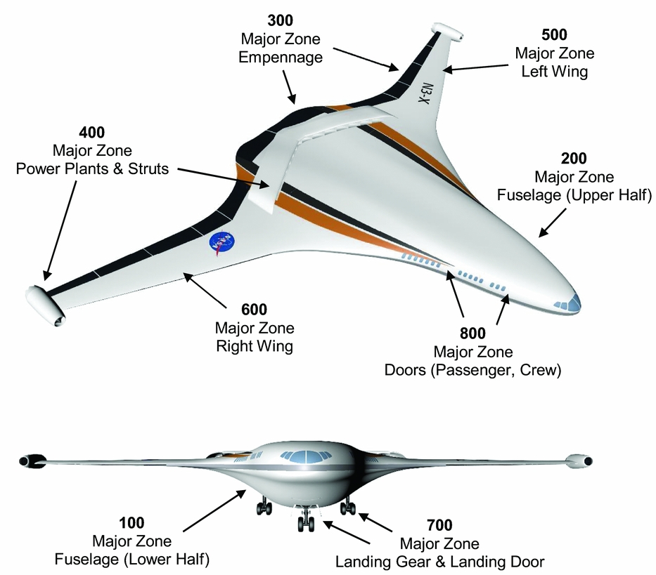
Figure 4. Major zone locations of NASA N3-X aircraft.
The major zones were subsequently broken down further into sub-major zones such as passenger cabins, power plants and fairings (see Fig. 5).
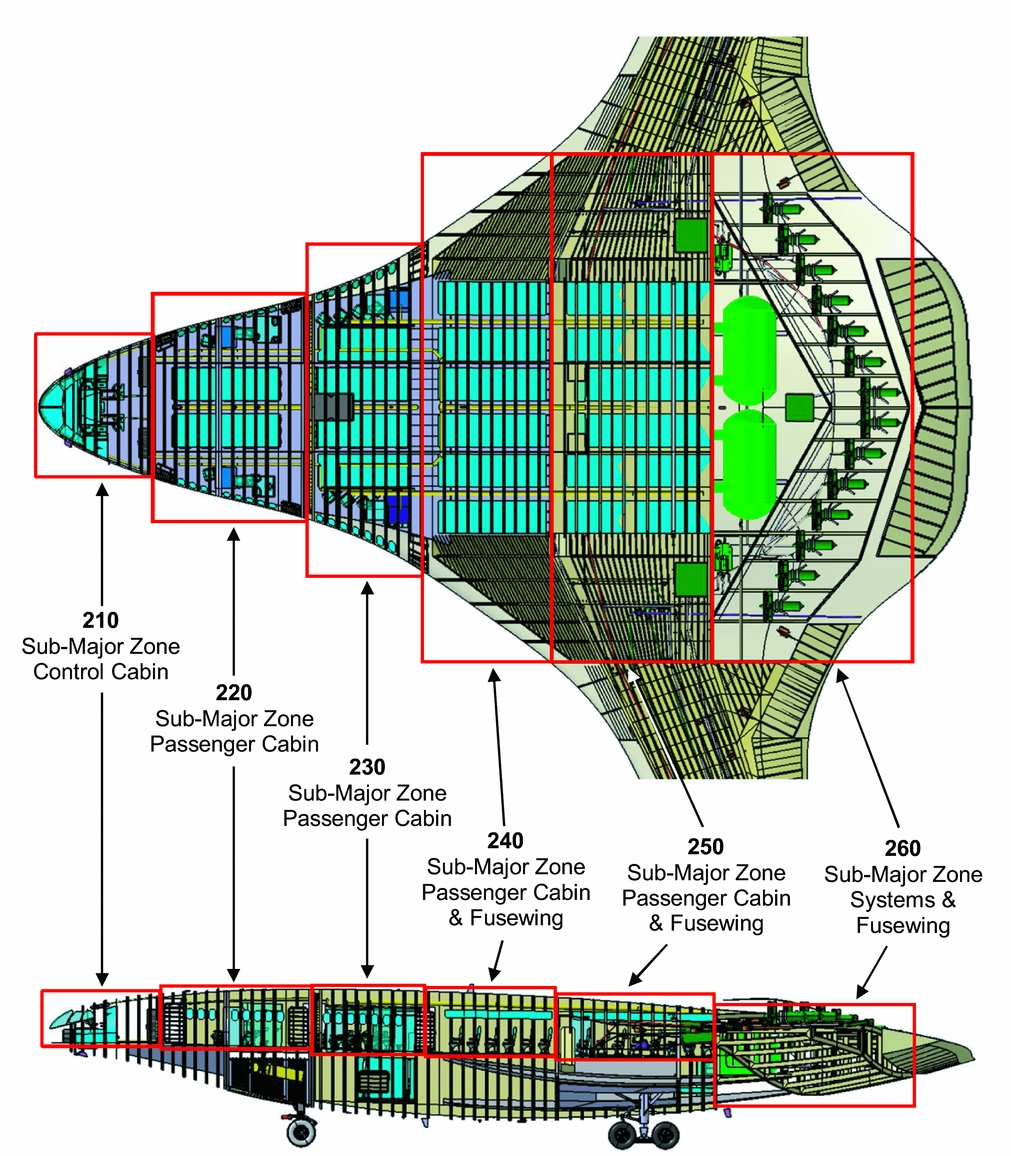
Figure 5. Breakdown of major zone 200 into sub-major zones.
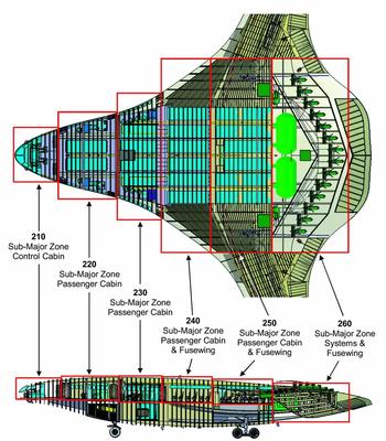
Smaller items/areas within these sub-major zones, such as specific fairings, engine cowl panels and fuselage doors, were then designated as zones. Specifically, the case study focused on the aft fuselage where the advanced technologies were located. Figure 6 shows the breakdown of sub-major zone 260 into zones.
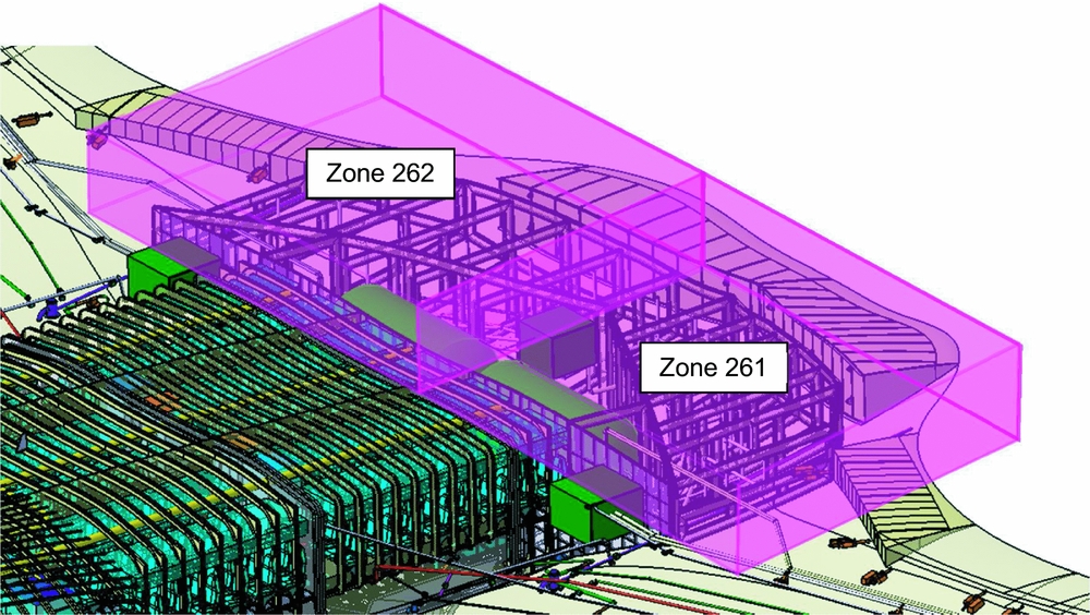
Figure 6. Breakdown of sub-major zone 260 into zones.
5.0 IDENTIFICATION OF ZONAL SYSTEMS/ITEMS
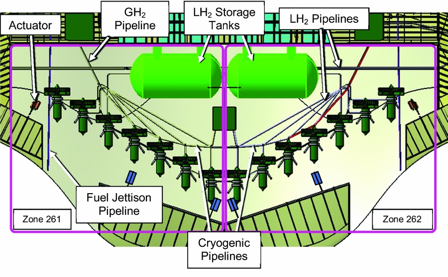
Subsequently, the aircraft design drawings were analysed, and the systems/items located within the zones of interest were identified. Since the focus of the study is on advanced technologies, the zones containing the cryogenic refrigeration system are examined in detail(Reference Lei9–Reference Papanikolaou12). Figure 7 shows the systems/items located within zones 261/262.

Figure 7. Systems/items in zones 261/262 (LH2 configuration).
The identified systems/items in each zone were then studied carefully to understand their preliminary design, system architecture and functions, as well as the maintenance hazards involved. This is important as it will facilitate the zonal safety inspection process later.
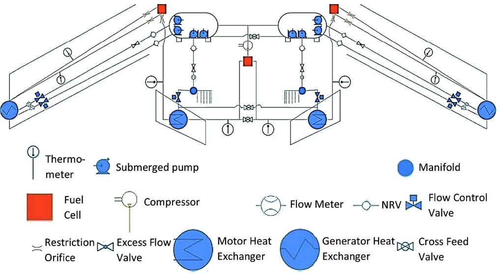
For example, the main purpose of having H2 on the NASA N3-X is to provide cryogenic refrigeration for the high-temperature superconducting (HTS) components (e.g. generators, motors) and transmission lines, as well as generate power for primary/secondary systems(Reference Al Zayat11). The cryogenic fuel (H2) feed architecture is shown in Fig. 8.

Figure 8. Cryogenic fuel (H2) feed architecture(Reference Al Zayat11).
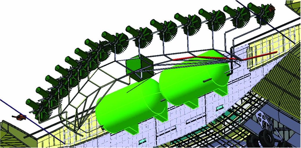
The submerged pumps in the LH2 storage tanks provide the required pressure to transfer LH2 from the tanks to the wing-tipmounted turbogenerator and propulsor fan motor heat exchangers via pipelines. After passing through the heat exchangers, the LH2 is converted to GH2 and channelled to the fuel cells via cryogenic pipelines. Any remaining hydrogen after the chemical reaction is returned to the LH2 storage tanks via a compressor. There are a total of four cryogenic pipelines in each wing. Two of them are LH2 pipelines leading from the LH2 storage tank to the wing-tip mounted turbogenerator, whereas the other two are GH2 pipelines (containing HTS transmission lines) from the wing-tip mounted turbogenerator to the fuel cells and propulsor fan motors(Reference Al Zayat11). The pipelines routing from the LH2 storage tanks to the fuel cells and propulsor fan motors are shown in Fig. 9.

Figure 9. LH2 storage tanks and cryogenic pipelines(Reference Al Zayat11).
There is a cross-feed valve installed between adjacent pipelines to the motors to provide redundancy. Hence, any single pipeline failure can be overcome by supplying LH2 across the cross-feed line. As for the LH2 storage tank, it comprises an internal tank (containing the LH2) surrounded by an insulation layer made of rigid closed cell polyvinachloride, which is then encapsulated by an external tank. This aim of this design is to keep the surface temperature of the internal tank low and minimise the boil-off mass of the stored LH2 during the flight. The tanks are made of aluminium to reduce weight and resist hydrogen embrittlement. The fluid in the tank consists of 98% LH2 and 2% GH2 at a temperature of around 20K(Reference Al Zayat11).
There is also a refuel/defuel and vent subsystem for the LH2 cryogenic system to refill/empty the LH2 storage tanks, and vent GH2 in the event of excessive pressure build-up in the tanks(Reference Al Zayat11). The refuel/defuel and vent system architecture is shown in Fig. 10.
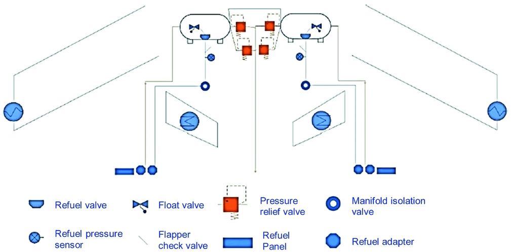
Figure 10. LH2 refuel/defuel and vent architecture(Reference Al Zayat11).
The tank pressure relief valve assembly consists of two relief valves and one electrically powered shut-off valve. The two relief valves allow for system redundancy –One relief valve acts as the ‘primary’ valve and maintains a pressure of 1.4 bar while the other relief valve is the ‘secondary’ valve and maintains pressure at 1.55 bar. The electrically-powered shut-off valve also acts as a vent valve(Reference Al Zayat11).
The tank removal procedure involves the use of three mini-hoists which are secured to the tank via cable attachment points. The tank is then tilted until a desirable angle is achieved so that the tank can be lowered through the lower fuselage access panel (see Fig. 11).
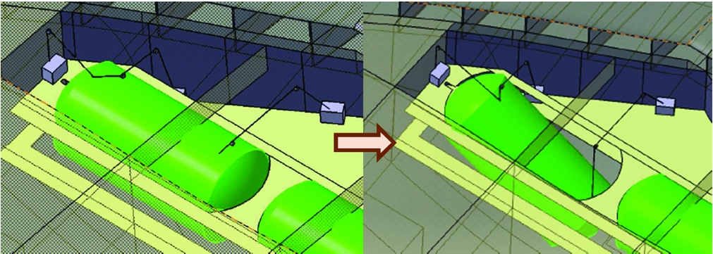
Figure 11. Securing and tilting of LH2 storage tank(Reference Frias13).
The tank is gradually lowered until it comes in contact with a trailer. Then, the tank is tilted in the opposite manner so that it is placed horizontally on the trailer(Reference Frias13). Figure 12 illustrates this process.
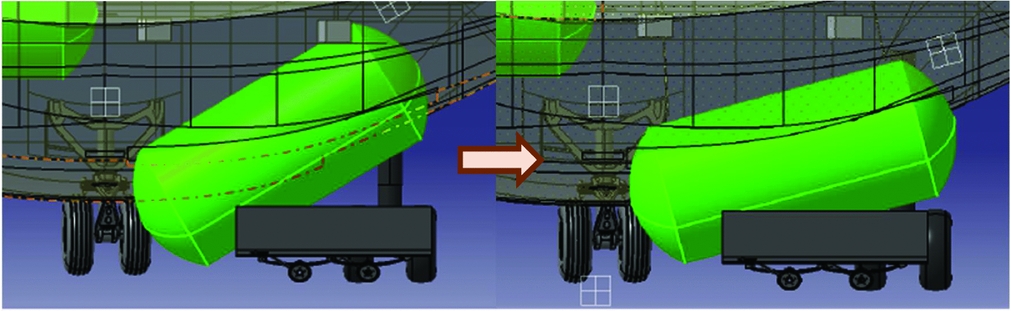
Figure 12. Placement of LH2 storage tank onto a trailer(Reference Frias13).
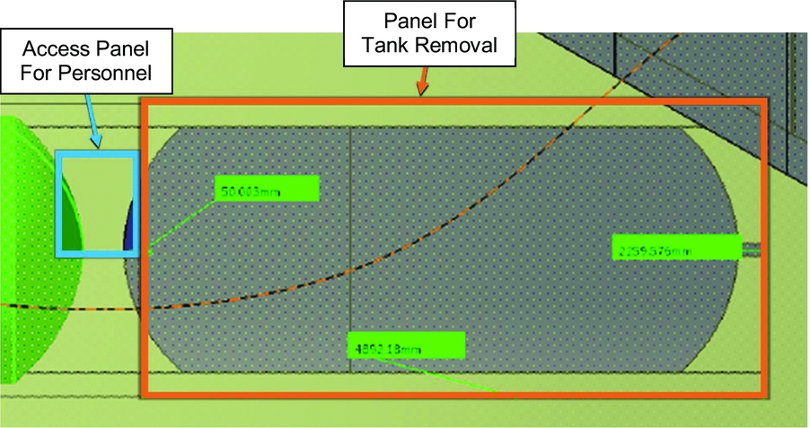
The LH2 storage tank has to be tilted during the removal process because the lower fuselage tank removal panel is shorter in length compared to the tank. This is due to the requirement to have a separate access panel for maintenance personnel, which limits the length of the lower fuselage tank removal panel(Reference Frias13). Figure 13 shows the locations of these panels.

Figure 13. Location of panels on aircraft lower fuselage(Reference Frias13).
6.0 DESIGN AND INSTALLATION GUIDELINES
The design and installation guidelines are mainly derived from the SAE Aerospace Standards (AS) which include recommended practices and information reports. These documents are sources of industry experience and provide knowledge on maintenance and operational hazards(14). However, the authors could not find any relevant standards regarding the design and installation of the LH2 storage system and fuel cell in the SAE archive of aerospace industry documents. This is probably because these systems have not been utilised in commercial aircraft yet. Therefore, the authors expanded their search beyond the aerospace industry and found relevant information in the ground vehicle industry (i.e. J2578 – Recommended Practice for General Fuel Cell Vehicle Safety(15) and J2579 – Standard for Fuel Systems in Fuel Cell and Other Hydrogen Vehicles(16)). Using the above-stated database, the authors developed the design and installation guidelines for the various zonal systems/items based on specific references (see Table 1).
Table 1 Systems/items in zones 261/262 (LH2 configuration)
Some of the design and installation guidelines developed for the LH2 cryogenic system are shown in Table 2.
Table 2 Some of the design and installation guidelines for LH2 cryogenic system
7.0 LIST OF SYSTEM EXTERNAL FAILURE MODES
With the information from the relevant SAE AS, Aerospace Information Report (AIR) and Aerospace Recommended Practice (ARP), the intrinsic hazards of the respective systems which could pose a danger to personnel safety or have an adverse effect on equipment were identified. As an example, the intrinsic hazards of the LH2 cryogenic system are shown in Table 3.
Table 3 LH2 cryogenic system intrinsic hazards

During the case study, the Failure Modes and Effects (FMES) was found to be incomplete as not all the system components had been finalised. Nevertheless, the system Functional Hazard Assessment (FHA) and Fault Tree Analysis (FTA) were available as the system architecture had been designed. Since the FHA established the failure conditions as well as their effects on the aircraft, crew and occupants, and the FTA determined the causes of a particular undesirable event, they provided relevant inputs to establish the list of system/item external failure modes having an effect on other systems/items installed in the same zone. With the system/item intrinsic hazards and FHA/FTA as inputs, the list of system external failure modes was developed. As an example, the external failure modes of the LH2 cryogenic system are shown in Table 4.
Table 4 LH2 cryogenic system external failure modes
Besides affecting other systems in the same zone, the external failure modes in the highlighted boxes in Table 2 were determined to have a potential effect on other zones as well.
8.0 ZONAL SAFETY INSPECTION
Since there was a lack of detailed electrical wiring and component installation drawings at the preliminary design stage, the zonal safety inspection focused on conformance to system design guidelines and examined the architectural layout of the respective components. The system external failure modes were also taken into account to identify any shortcomings in the preliminary system design which may have an adverse effect on other systems. As an example, the inspection results for the LH2 cryogenic system are shown in Table 5.
Table 5 LH2 cryogenic system inspection findings
9.0 RISK ASSESSMENT
All findings from the zonal safety inspection were assessed for their risk level using the risk assessment matrix found in ARP5151(5), which assesses the severity and probability of a potential hazard. The risk assessment matrix intersection of the hazard probability and severity defines the relative risk of the hazard (see Table 6).
Table 6 Risk assessment matrix (ARP5151)(5)

The risk assessment was conducted qualitatively, based on the possible consequences and the likelihood of hazard occurrence. The risk assessment process is shown in Table 7 using two of the inspection findings as examples.
Table 7 Examples of risk assessment process
In summary, out of the 56 safety findings, there were 10 counts of ‘extremely high’ risk, 7 counts of ‘high’ risk, 33 counts of ‘medium’ risk and 6 counts of ‘low’ risk (see Table 8).
Table 8 Summary of risk assessment
10.0 RECOMMENDATIONS TO MITIGATE RISKS
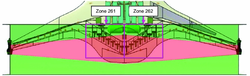
After assessing the hazard risk level, the next step is to identify the root causes and extent of the problem. This enables the appropriate corrective action (i.e. modification to design or maintenance practice) to be adopted. Here are some examples of the proposed recommendations to mitigate the ‘extremely high’ risks (represented by red-coloured boxes) found in zones 261/262 (see Fig. 14).
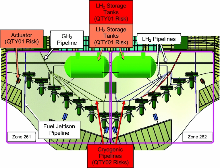
Figure 14. ‘Extremely high’ and ‘high’ risks in zones 261/262.
Example #1:
Affected System/Component: LH2 Storage Tanks
Risk Level: Extremely High
Description of Hazard: LH2 storage tank might fracture/break resulting in hydrogen seepage/leakage (i.e. fire risk).
Root Cause(s): Lack of detailed study regarding the effect of fuselage structural loading on the LH2 storage tanks –the selection of aluminium as the material for both inner and outer tanks may not be suitable (aluminium has low strength and becomes too brittle for use at low temperatures of 20K).
Recommendation(s): Material with higher strength and toughness, as well as better compatibility when working at low temperatures, such as aluminium 5000 series alloys (in the as-welded condition) and 300 series stainless steel (in the annealed condition) should be selected. It is recommended that aluminium 5000 series alloy be used as the inner tank material since there is relatively low structural loading. The outer tank can be made of 321 corrosion-resistant steel as it has higher strength and toughness – it will be able to protect the rigid closed-cell polyvinachloride insulation layer and inner tank from any external forces (e.g. impact loading). This will achieve a balance between minimising weight and ensuring system integrity.
Example #2:
Affected System/Component: LH2 Storage Tanks
Risk Level: High
Description of Hazard: LH2 storage tank might fracture/break resulting in hydrogen seepage/leakage (i.e. fire risk).
Root Cause(s): Tank removal/installation procedures are too complex and will introduce uneven loads on the tank surface (due to tilting); the tank is also susceptible to knocks while tilting which will affect the structural integrity of the tank.
Recommendation(s): Relocate the access panel for maintenance personnel away from the axis of the LH2 storage tanks to below the fuel cell. (It has been verified that there is sufficient height clearance of at least 1 metre between the lower working platform and the fuel cell – this will enable maintenance personnel to climb up to the lower working platform and access the LH2 storage tanks from there.) This will allow the lower fuselage tank removal panels to be re-designed such that they are at least as long as the LH2 storage tanks. Therefore, there will no longer be any requirement to tilt the LH2 storage tanks during removal and they can be lowered horizontally onto the trailer. This eliminates the risk of introducing uneven loads on the tank surface (due to tilting) and incurring any knocks while trying to lower the tank through a smaller gap. Figure 15 shows the recommended locations of the panels.
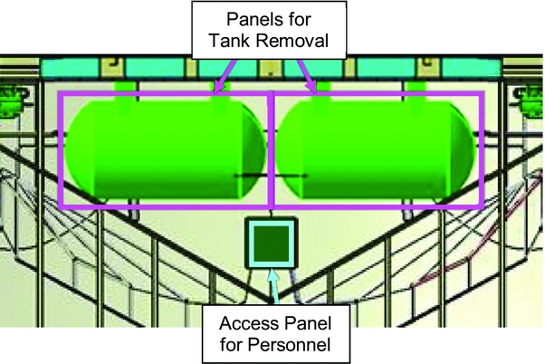
Figure 15. Recommended locations of lower fuselage panels.
11.0 DISCUSSION OF RESULTS
The proposed recommendations have enhanced the preliminary design of the NASA N3-X aircraft in terms of system and maintenance safety. By following the steps stated in the PZSA methodology, the preliminary aircraft configuration was partitioned into zones; systems and components were identified for each zone; design and installation guidelines were developed for the respective systems; system external failure modes were derived for each zone; zonal safety inspection was performed; risk assessment was carried out for any safety findings and recommendations were proposed to mitigate hazards with ‘high’ risk level and above. Therefore, this methodology provided a holistic approach of analysing aircraft safety at the preliminary design stage, by considering both intra-and inter-system effects within the same zone. This was verified using the NASA N3-X aircraft as a case study.
Nonetheless, there are several lessons learnt from the case study and the PZSA methodology can still be improved. First, the input to facilitate the development of design and installation guidelines could be expanded beyond SAE Aerospace Standards to include other information sources. This would be useful especially when dealing with advanced technologies that have not been implemented in the aviation industry. For example, LH2 has been used as a fuel in automobiles and the ground vehicle industry already has the relevant experience and expertise. Therefore, the author developed the design and installation guidelines for the fuel cell based on J2578 – Recommended Practice for General Fuel Cell Vehicle Safety. Similarly, the design and installation guidelines for the LH2 storage system were based on J2579 – Standard for Fuel Systems in Fuel Cell and Other Hydrogen Vehicles.
Another issue was the lack of detailed electrical wiring and component installation drawings available to conduct the zonal safety inspection. This was because the routing of electrical wires and the type of brackets/hoses/couplings to be used for component installation had not been determined by the NASA N3-X aircraft designers. In retrospect, this was reflective of an actual preliminary design phase where the aircraft configuration had just been ‘frozen’ with only the major items being designed(Reference Raymer3). Therefore, it was not practical to perform an inspection on component installation at the preliminary aircraft design stage. Instead, it would be more beneficial to check on the overall architecture of the system components by inspecting the positional layout of major components. For example, food containers which may have spillages should not be positioned above electrical equipment to avoid shorting.
The third issue was the lack of component FMEA details during the preliminary design stage to facilitate the identification of system external failure modes. This was because details of the system components have not been finalised during the preliminary design stage and it was not possible to carry out the FMEA for all system components yet. Nevertheless, the system FHA and FTA on the system had been finalised and could be used as inputs to derive the list of system external failure modes. The FHA identified the system failure conditions as well as their effects on the aircraft, crew and occupants, while the FTA determined the causes of a particular undesirable event. Therefore, they could still provide inputs to establish the list of system/item external failure modes having an effect on other systems/items installed in the same zone.
The fourth way to improve the methodology was by considering the inter-zonal failure effects of particular system external failure modes when performing the zonal safety inspection. As mentioned earlier, some of the system external failure modes were determined to have a potential effect on other zones and should be included in the zonal safety inspection for the affected zones. For example, any leakage from the LH2 storage tanks would result in the formation of gaseous hydrogen which can seep into the surrounding zones – resulting in a flammable environment (i.e. fire risk).
Using the NASA N3-X case study, an example of such an inter-zonal failure effect that could affect zones 261 and 262 was the turboshaft engine rotor burst. Although the engine is located outside of zones 261 and 262, a rotor burst may penetrate and damage components within these zones. Figure 16 shows the aircraft portions that are affected by an engine rotor burst (highlighted in red).

Figure 16. Portions affected by engine rotor burst (highlighted in red)(Reference Al Zayat11).
The engine rotor burst analysis shows that the LH2 storage tanks, helium cryocoolers and cryogenic pipelines leading to the wing-tip turbogenerator heat exchangers are located outside of the turboshaft engine rotor burst zones. However, the cryogenic pipelines from the LH2 storage tanks leading to the propulsor fan motor heat exchangers are located within the engine rotor burst zone(Reference Al Zayat11). Applying the risk assessment matrix found in ARP5151, it was assessed to have ‘catastrophic’ hazard severity and ‘improbable’ hazard probability. Therefore, the hazard risk level was ‘low’. Since it was a certification requirement to design for protection against rotor burst, it was recommended that some parts of the aircraft aft fuselage should be reinforced to provide protection against rotor penetration. Figure 17 shows the parts of the aft fuselage to be reinforced (indicated in red).
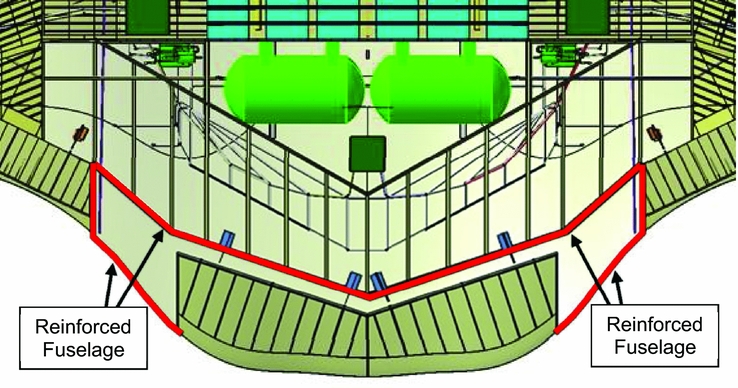
Figure 17. Portions of aft fuselage recommended for reinforcement.
From this example of an engine rotor burst, it is seen that inter-zonal failure effects can influence system/structural design significantly. Therefore, it is important to include them in the PZSA methodology to provide a complete safety analysis of the entire aircraft. Figure 18 shows the refined PZSA methodology to be used for preliminary aircraft design (refinements are indicated in orange).
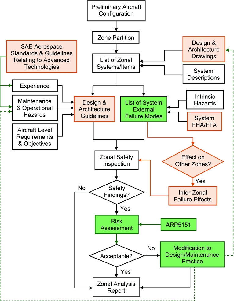
Figure 18. Refined PZSA methodology for preliminary aircraft design.
12.0 CONCLUSIONS
In order to develop a PZSA methodology that was suitable for preliminary aircraft design, the methodologies found in ARP4761 and related past year thesis(Reference Yu6) was analysed. Opportunities for improvement were identified and a new methodology was proposed. It was then applied to a selected aircraft – NASA N3-X – as a case study to verify the procedural steps.
From the case study, several lessons were learnt which led to the refinement of the methodology. The lessons include: (1) Expansion of inputs beyond SAE Aerospace Standards to include other sources relating to advanced technologies, (2) Re-focusing of the zonal safety inspection to cover system design and architectural layout, (3) Inclusion of system FHAs/FTAs as inputs to develop the list of system external failure modes, and (4) Considering the inter-zonal failure effects of system external failure modes when performing the zonal safety inspection.
In conclusion, the refined PZSA methodology had been tested and verified through a case study of the NASA N3-X aircraft design. The methodology should be adopted by aircraft designers during preliminary design as it would enhance aircraft design safety by considering intra-and inter-system effects within the same zone. In addition, it would help the project to reduce design/development costs by identifying system interference issues early, and avoiding costly modifications during the later design/development stages.
13.0 FURTHER WORK
There are two areas where further work may be carried out. First, the input sources for ‘experience’ (as mentioned in the methodology) can be expanded beyond SAE to include other relevant agencies such as NASA. This is especially for advanced technologies which may have already been practised in spacecraft, but have not been implemented in the aviation industry. Second, the risk assessment of safety findings can be taken one step further by quantifying the associated risks. This can be done using the Acceptable Means of Compliance (AMC) 25.1309 on systems design and analysis. This would provide a more in-depth risk assessment of the hazards.