


1. Introduction
Human hands may suffer from loss of functionality and muscles weakness, which can significantly affect daily life activities [Reference Heo, Gu, Lee, Rhee and Kim1,Reference Stein, Bishop, Gillen and Helbok2]. In recent years, robotic technologies have been applied in motion rehabilitation to provide training assistance and quantitative assessments of recovery with a significant potential cost reduction as compared with manual approaches [Reference Bataller, Cabrera, Clavijo and Castillo3,Reference Sarac, Solazzi and Frisoli4]. Several exoskeleton prototypes are reported in a large literature such as those that are proposed in refs. [Reference Bataller, Cabrera, Clavijo and Castillo3,Reference Aragón-Martínez, Arias-Montiel, Lugo-González and Tapia-Herrera13]. However, existing exoskeletons usually are limited to laboratory prototypes, which often demonstrate well-known limitations that prevent their practical implementation in market products. The main problems with existing exoskeletons consist of lack of adaptability to different users, such as shown, for example, in ref. [Reference Bataller, Cabrera, Clavijo and Castillo3]; the bulky prototype sizes, such as shown, for example, in ref. [Reference Agarwal, Fox, Yun, O’Malley and Deshpande5], or the need of a bulky or not easily portable control equipment, as shown, for example, in ref. [Reference Cempini, Cortese and Vitiello6], or difficulties in wearing them, as shown, for example, in ref. [Reference Li, He, Liang, Zhao, Chen, Zhuo, Xu, Xie and Althoefer7].
Several researchers have been attempting to overcome the limitations of the existing exoskeletons looking at several different aspects, such as control-based mechanism design as for example in ref. [Reference Aragón-Martínez, Arias-Montiel, Lugo-González and Tapia-Herrera14], multi-link/DOFs mechanism with EMG-based operation as for example in ref. [Reference Jana, Barua and Hazarika15], and compliant operation of flexible mechanisms as for example in ref. [Reference Li, Yan and Ren16]. The team led by prof. Ceccarelli and prof. Carbone has been addressing this topic for more than 20 years by focusing on fundamental grasping mechanics as well as on the design and validation of anthropomorphic robotic hands [Reference Carbone, Iannone and Ceccarelli17,Reference Carbone18]. Recently, a novel exoskeleton named as ExoFing has been designed and built with prototypes at both LARM2 and DIMEG [Reference Carbone, Gerding, Corves, Cafolla, Russo and Ceccarelli19,Reference Gerding, Ceccarelli, Carbone, Cafolla and Russo20].
This paper aims at reporting experiences and results for validating main operation characteristics of ExoFing for different users and operation conditions also demonstrating its feasibility as a cost-oriented and user-friendly solution for motion assistance of a human index finger.
2. The ExoFing finger exoskeleton
The ExoFing device is based on a specifically designed 2-DOFs (degrees-of-freedom) driving mechanism. The parameters and the configuration of the proposed eight-bar mechanism allow to replicate the human finger motion and to adapt it for different finger sizes. Main design details are reported within a specific Italian patent [Reference Gerding, Ceccarelli, Carbone, Cafolla and Russo20].
The ExoFing system consists of two interconnected four-bar mechanisms allowing two active DOFs that are driven using two servomotors. A conceptual scheme of the mechatronic design of ExoFing is outlined in Fig. 1. The full mechatronic setup of ExoFing includes two servomotors and several sensors that are managed within an Arduino-based control architecture. The data acquisition is carried out by using four different types of sensors as reported in Fig. 1, namely a temperature sensor (1), which is located on the metacarpus phalange to identify the change of temperature during the motion exercise, a bioelectrical activity sensor (2), which is installed to determine the electrical response of the finger, a current sensor (3), which is used to estimate the energy consumption of the device, and two IMU sensors (4), which are placed on the metacarpus and distal phalanges to identify the angle displacements and angular velocities of the finger joints.

Figure 1. A conceptual scheme of ExoFing.
ExoFing is designed with main features for portability and adaptability for a wide range of users. In particular, the design considers possible attachment regions where the attachment points fix the device on the finger for different subjects. Figure 2 shows a kinematic scheme with motors to drive each DOF in a general position as to be installed on a human hand and finger. The input angle for the first four-bar mechanism is labeled as
 $\delta$
, and the input angle for the second mechanism is marked as
$\delta$
, and the input angle for the second mechanism is marked as
 $\beta$
. The device uses four attachment points, namely one for the palm and the back of the hand (A1), two for the metacarpus phalange (A2 and A3), and the last one for distal phalange (A4). These four points give the device the possibility to be fixed for different anthropomorphic sizes. Therefore, the behavior of the system could differ for different users, since there is a change in the distances between the metacarpal joint (MCP), the proximal interphalangeal joint (PIP), and the distal interphalangeal joint (DIP) can be at a different distance too.
$\beta$
. The device uses four attachment points, namely one for the palm and the back of the hand (A1), two for the metacarpus phalange (A2 and A3), and the last one for distal phalange (A4). These four points give the device the possibility to be fixed for different anthropomorphic sizes. Therefore, the behavior of the system could differ for different users, since there is a change in the distances between the metacarpal joint (MCP), the proximal interphalangeal joint (PIP), and the distal interphalangeal joint (DIP) can be at a different distance too.

Figure 2. A kinematic design of ExoFing.
Numerical data of the design parameters both in the CAD model and the experimental prototype are defined by referring to the values of an average index available in the literature as reported in ref. 15 and summarized in Table I.

3. Numerical evaluation of operation performance
3.1 Kinematic analysis
Figure 3 shows a CAD design of ExoFing indicating the position of the inputs
 $\delta$
and
$\delta$
and
 $\beta$
. The point A4 stands for the attachment point of the exoskeleton on the fingertip, while A1 is the attachment point between first servo housing and finger. The kinematic analysis aims at obtaining the angular position of the DIP joint to be compared with the angular displacement measured with the prototype in laboratory tests.
$\beta$
. The point A4 stands for the attachment point of the exoskeleton on the fingertip, while A1 is the attachment point between first servo housing and finger. The kinematic analysis aims at obtaining the angular position of the DIP joint to be compared with the angular displacement measured with the prototype in laboratory tests.

Figure 3. A CAD model of ExoFing design with a front view.
To evaluate the motion of fingertip and first phalange, a kinematic analysis of the ExoFing has been carried out for each four-bar linkage of the mechanism, as referring to the scheme in Figs. 2 and 3. The first four-bar linkage is D 0 -D-E-A 2 , and its kinematical behavior can be described by solving the closure equation:
 \begin{align}\overline {{A_1}{D_0}} + \overline{{D_0}D} + \overline {DE} + \overline {E{A_2}} + \overline {{A_2}{A_1}} = 0\end{align}
The second four-bar mechanism is given by B 0-B-A-A 0 and its closure equation can be written as:
 \begin{align}\overline {{B_0}B} + \overline {BA} + \overline {A{A_0}} + \overline {{A_0}{B_0}} = 0\end{align}
Capital letters in Fig. 3 are used to highlight exoskeleton points. In particular, B 0 and D 0 define the shaft positions of the two servomotors, respectively. It is to note that in the CAD design in Fig. 3, point E is located as coinciding with A 0 using the same joint pin and those only distances between the joints are considered for this kinematic model.
From Eqs. (1) and (2), a set of two equations can be obtained by projecting their vector component to the x-y fixed reference frames. Accordingly, Eqs. (1) and (2) are squared and summed. This leads to the following equations:
 \begin{align}\overline {D{E^2}} &= {\overline {{D_0}D} ^2} + {\overline {E{A_2}} ^2} + {\overline {{A_2}{A_1}} ^2} + {\overline {{A_1}{D_0}} ^2} - 2\left( {\overline {{D_0}D} } \right)\left( {\overline {E{A_2}} } \right)\left( {\cos \delta \cos {\theta _M} + \sin \delta \sin {\theta _M}} \right)\nonumber\\[3pt] &\quad - 2\left( {\overline {{A_2}{A_1}} } \right)\left( {\overline {{D_0}D} \cos \delta - \overline {E{A_2}} \cos {\theta _M}} \right) + 2\left( {\overline {{A_1}{D_0}} } \right)\left( {\overline {{D_0}D} \sin \delta - \overline {E{A_2}} \sin {\theta _M}} \right)\end{align}
and
 \begin{align}{\overline {BA} ^2} & = {\overline {{B_0}B} ^2} + {\overline {A{A_0}} ^2} + {\overline {{A_0}{B_0}} ^2} - 2\left( {\overline {{B_0}B} } \right)\left( {\overline {A{A_0}} } \right)\left( {\cos \beta \cos {\theta _{FT}} + \sin \beta \sin {\theta _{FT}}} \right)\nonumber\\[3pt] &\quad - 2\left( {\overline {{A_0}{B_0}_x} } \right)\left( {\overline {{B_0}B} \cos \beta - \overline {A{A_0}} \cos {\theta _{FT}}} \right) + 2\left( {{{\overline {{A_0}{B_0}} }_y}} \right)\left( {\overline {{B_0}B} \sin \beta - \overline {A{A_0}} \sin {\theta _{FT}}} \right)\end{align}
In Eq. (3),
 $\delta$
is the input angle parameter of the first servomotor. The action of the first servomotor sets the angle between the metacarpus phalange and the x frame for a desired motion output. The metacarpus phalange is fixed at the E-A
2 link of the first four-bar mechanism using a Velcro strap. Accordingly, a desired motion of the metacarpus phalange is assigned by the angular motion of E-A
2 link. The output angular motion of E-A
2 link can be calculated by solving the Eq. (3) for each input value that is imposed to D
0-D link from the first servomotor. Figure 4 shows a plot of the computed angles spanning by the metacarpus phalange in a subset of its flexion motion when the input angle
$\delta$
is the input angle parameter of the first servomotor. The action of the first servomotor sets the angle between the metacarpus phalange and the x frame for a desired motion output. The metacarpus phalange is fixed at the E-A
2 link of the first four-bar mechanism using a Velcro strap. Accordingly, a desired motion of the metacarpus phalange is assigned by the angular motion of E-A
2 link. The output angular motion of E-A
2 link can be calculated by solving the Eq. (3) for each input value that is imposed to D
0-D link from the first servomotor. Figure 4 shows a plot of the computed angles spanning by the metacarpus phalange in a subset of its flexion motion when the input angle
 $\delta$
ranges from 54o to 34.5o and the speed of motor 1 is assumed to be constant as equal to 1.2 rad/s. In Eq. (4), the input parameter is
$\delta$
ranges from 54o to 34.5o and the speed of motor 1 is assumed to be constant as equal to 1.2 rad/s. In Eq. (4), the input parameter is
 $\beta$
and given
$\beta$
and given
 $\theta$
FT
, the angle between distal phalange and the x frame, is the output and can also be seen as the sum of
$\theta$
FT
, the angle between distal phalange and the x frame, is the output and can also be seen as the sum of
 $\theta$
M
,
$\theta$
M
,
 $\theta$
P
, and
$\theta$
P
, and
 $\theta$
D
, which are defined as referring to the scheme in Fig. 2. Furthermore in Eq. (4), subscripts x and y are used to identify A
0
B
0 link projections on the fixed reference frame axes x and y, respectively. In the second four-bar mechanism, the fixed frame B
0
A
0 moves constantly due to the motion of D-E link to which it is rigidly linked. The fingertip and the whole distal phalange are fixed at the frame with prismatic joint, which is represented by the point C in Fig. 3.
$\theta$
D
, which are defined as referring to the scheme in Fig. 2. Furthermore in Eq. (4), subscripts x and y are used to identify A
0
B
0 link projections on the fixed reference frame axes x and y, respectively. In the second four-bar mechanism, the fixed frame B
0
A
0 moves constantly due to the motion of D-E link to which it is rigidly linked. The fingertip and the whole distal phalange are fixed at the frame with prismatic joint, which is represented by the point C in Fig. 3.

Figure 4. Computed angles for metacarpal phalange angular motion.
The design parameters in the CAD model of Fig. 3 that are also used subsequently for the construction of the prototype are summarized in Table I.
This joint is linked to the second four-bar mechanism with a connecting rigid body whose links are B-C and A-C. Link A-C forms a fixed angle of almost 35o with B-A link and another one of almost 57o relative to the distal phalange. Solving Eq. (4), for each value of
 $\beta$
, the angle assumed by B-A link can be computed. Even the angle between A-C link and the x axis can be computed adding to the angle assumed by B-A link the fixed angle of 35o, since its value is given by the difference of the A-C link angle and the fixed one of 57o, lying between the A-C link and the distal phalange. Figure 5 shows the calculated angle between the distal phalange and the x axis in a subset of its flexion motion when the input angle
$\beta$
, the angle assumed by B-A link can be computed. Even the angle between A-C link and the x axis can be computed adding to the angle assumed by B-A link the fixed angle of 35o, since its value is given by the difference of the A-C link angle and the fixed one of 57o, lying between the A-C link and the distal phalange. Figure 5 shows the calculated angle between the distal phalange and the x axis in a subset of its flexion motion when the input angle
 $\beta$
ranges from 19.4o to 3.4o and the speed of the motor 2 is constant at 1 rad/s. It is to note that Eqs. (3) and (4) are solvable only when
$\beta$
ranges from 19.4o to 3.4o and the speed of the motor 2 is constant at 1 rad/s. It is to note that Eqs. (3) and (4) are solvable only when
 $\delta$
is within a certain range. At about 34o, there is a numerical uncertainty due to the alignment of both D-E and E-A
2
links. In fact, when
$\delta$
is within a certain range. At about 34o, there is a numerical uncertainty due to the alignment of both D-E and E-A
2
links. In fact, when
 $\delta$
is less than 34o in Eq. (3), EA
2 link’s projection on the x frame will have a sign change.
$\delta$
is less than 34o in Eq. (3), EA
2 link’s projection on the x frame will have a sign change.

Figure 5. Computed angles for distal phalange angular motion.
Referring to the scheme in Fig. 3, the distal phalange is attached to the mechanism in A 4. Once the exoskeleton is fixed to the hand, the motion of point C can be produced as providing the distal phalange motion. Figure 6 shows the calculated motion of point C when assuming an input motion of motor 1 and motor 2 to start at 54o and 19.4o, respectively. The speeds of both motors are assumed constant. Accordingly, it is expected that point C spans from about 100 to 65 mm along x direction and from 30 to 70 mm along y direction, as referring to the fixed reference frame in Fig. 3.

Figure 6. Computed feasible motion of point C using the proposed kinematic model.
3.2 Multibody simulation
A multibody model of the mechanism has been created by using the Motion environment of Simcenter 3D software [Reference Siemens21]. This model includes a 3D CAD model of each component of the ExoFing assembly. This CAD model also provides realistic estimates of the inertia properties of each component with main links made of commercial PLA plastic for 3D printing. The proposed model also incorporates a simplified model of a finger with standard average dimensions, as shown in the snapshot of simulation in Fig. 7. It is to note that Velcro straps are used to attach and adapt the ExoFing device to a wide range of users. The compliance of Velcro straps plays a fundamental role in widening the range of feasible users and motions. Accordingly, careful attention has been addressed at providing a suitable modeling of the Velcro straps clearance. This compliance has modeled in the proposed multibody model through lumped linear spring-damper elements at the interface between the finger and the ExoFing device with stiffness and damping parameters set as K = 1000 N/mm and C = 1 N/(mm/s), respectively. Additionally, torsional spring-damper elements have been located at PIP and DIP joints, (Fig. 2), with stiffness and damping parameters set as K = 50 Nmm/deg and C = Nmm/(deg/s), respectively, to model the finger bending resistance. The above specific stiffness and damping parameters have been estimated and tuned to be closely matching the experimental behavior of the Velcro straps and finger bending, respectively.
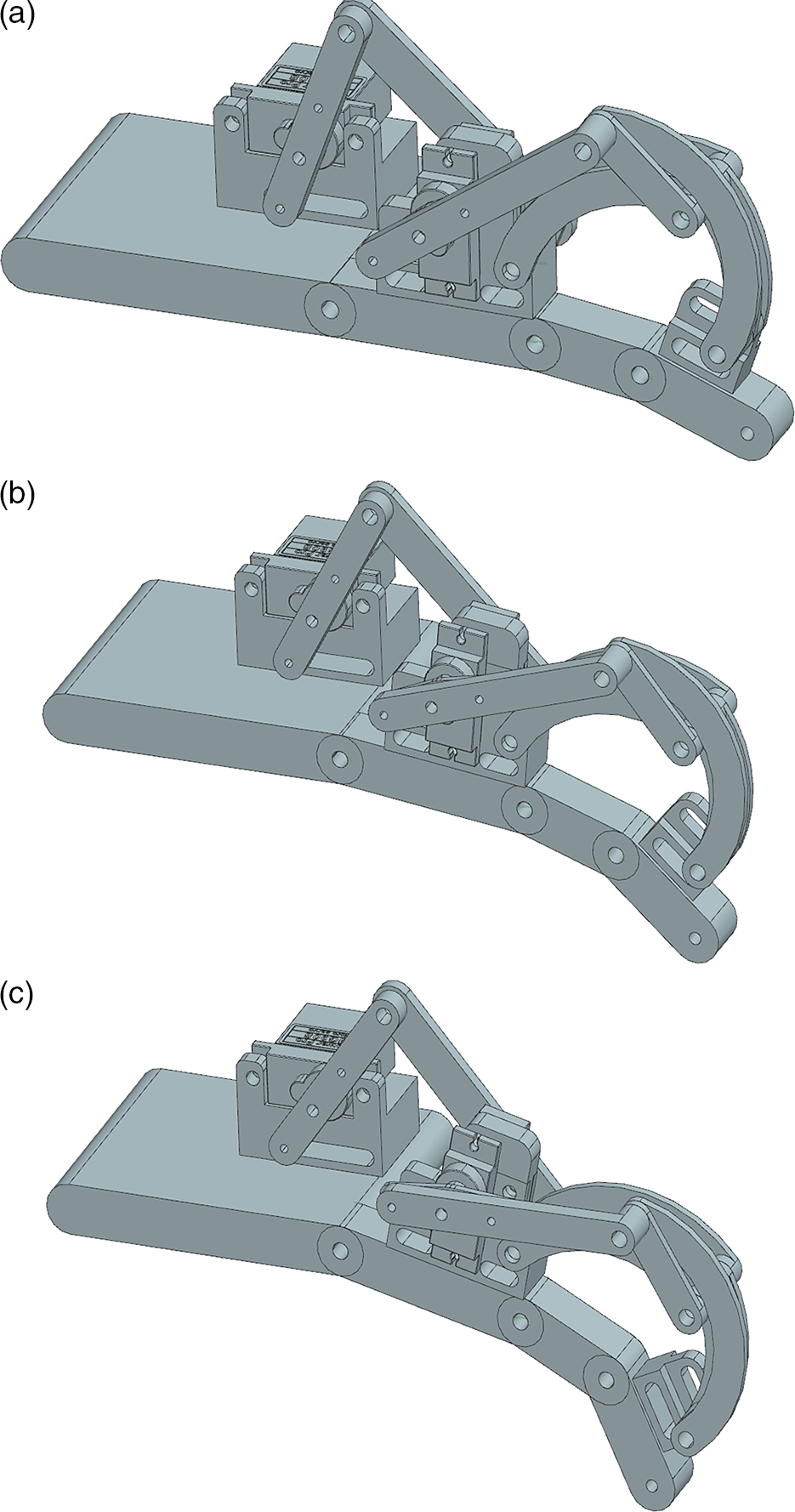
Figure 7. Snapshots of the exoskeleton multibody simulation during a closure motion: (a) starting; (b) during motion; and (c) final position.
The above-mentioned model was used for simulating several operation conditions, also considering the input data, which have been provided by the kinematic model in terms of input motions. This allows to estimate position, velocity, and acceleration of each body and joint in the model, together with the torques needed for the actuation. For example, a movement has been simulated starting from the fully extended finger configuration and taking 0.25 s for achieving the same movement, which has been reported in Figs. 4 and 5. These results in a finger motion are reported in Fig. 7 with three model snapshots, namely start, intermediate, and final configurations.
Based on the simulated motion in Fig. 7, it has been possible to compute the required motor torques which are reported in Figs. 8 and 9 for motor 1 and 2, respectively. Results in Figs. 8 and 9 show a maximum required torque of about 1.2 Nm in the test operation conditions. This confirms the feasibility of using low-cost commercial off-the-shelf digital servomotors as actuators for the ExoFing prototype. Similarly, simulations in Figs. 10 and 11 report the required motor power consumptions for motor 1 and 2, respectively. One can note from Figs. 10 and 11, a maximum power consumption is estimated as low as about 1.5 W for motor 1 and 2 W for motor 2 with an overall maximum consumption of 3.5 W. This result confirms the possibility to use a commercial LiPo battery for ExoFing operation with an estimated autonomy of several hours.

Figure 8. Computed values of the input motor 1 torque for the case shown in Fig. 7.

Figure 9. Computed values of the input motor 2 torque for the case shown in Fig. 7.

Figure 10. Computed values of the power consumption of motor 1 for the case shown in Fig. 7.

Figure 11. Computed values of the power consumption of motor 2 for the case shown in Fig. 7.
4. Experimental setup and tests
A prototype has been built and tested both at LARM2 in Rome and at DIMEG in Rende. The implemented experimental setup at LARM2 includes an EMG sensor, two IMU sensors (IMU 1 and IMU 2), a temperature sensor, and a current sensor (SC) (Fig. 12). The whole testing setup is based on an Arduino board, which also controls the two servomotors driving the ExoFing prototype and regulating their angular positions by using the embedded encoders. The prototype has been built by carefully considering the average index finger sizes with an overall weight of about 300 g at a cost of about 100 Euros for purchasing its main off-the-shelf components in Italy. In particular, the linkage structure has been manufactured with 3D printing with PLA of 50 grams of weight only.

Figure 12. Design of experimental setup at LARM2 in Rome: (a) a conceptual scheme and (b) a laboratory setup. (1: temperature sensor, 2: EMG, 3: current sensor, 4: IMU’s, 5: motors, and 6: Arduino).
A conceptual scheme of the proposed experimental setup is reported in Fig. 12(a). In particular, this scheme gives an overview on the arrangement of each component. Figure 12(b) shows a human hand while wearing a ExoFing prototype with the above-mentioned sensory setup with: (1) temperature sensor at the metacarpus phalanx; (2) electrodes for the EMG sensor; (4) the IMU 1 on the metacarpus phalanx for measuring the angular displacement
 $\theta$
M
of the metacarpus phalanx and its corresponding angular speed, and the IMU 2 attached at the distal phalanx for measuring the angular displacement
$\theta$
M
of the metacarpus phalanx and its corresponding angular speed, and the IMU 2 attached at the distal phalanx for measuring the angular displacement
 $\theta$
D
and its corresponding angular speed; and (5) one servomotor drives the first four-bar mechanism with input
$\theta$
D
and its corresponding angular speed; and (5) one servomotor drives the first four-bar mechanism with input
 $\delta$
and the other servomotor drives the second linkage with input labeled as
$\delta$
and the other servomotor drives the second linkage with input labeled as
 $\beta$
in Fig. 2.
$\beta$
in Fig. 2.
Experiments have been carried out by considering two testing modes. For the first testing mode, the full finger motion is considered by driving both servomotors starting at fully stretched finger configuration and moving toward the palm. The second testing mode consists of actuating only the servomotor 2 to drive only the second linkage mechanism starting from the same initial configuration that is defined in the previous experiment and, consequently, it allows to achieve only the motions of the proximal (PIP) and distal (DIP) phalanx
5. Experimental results
An experimental campaign with different subjects was carried out in a laboratory environment with subjects whose index fingers, albeit with different dimensions but close to the used average design value, were successfully tested with the ExoFing prototype. Experimental results consist of the experimental data that have been obtained with the used four sensors aiming at determining the effectiveness of the device when used by different subjects.
An example of a tested motion obtained by using ExoFing is shown in Fig. 13, where snapshots show a finger that is moving from the fully extended configuration in Fig. 13(a), to partial flexion in Fig. 13(b), and a complete flexion is achieved in Fig. 13(c).

Figure 13. Snapshots of the exoskeleton motion during a test with sensors: (a) starting position; (b) intermediate position; and (c) fully closed position.
The experimental results for this experiment are reported in Figs. 14–17. In particular, Fig. 14(a) reports the experimental test results in terms of measured angular motor inputs
 $\delta$
and
$\delta$
and
 $\beta$
versus time. The measured angular motor input shows a maximum operation range of about 60 degrees and properly follows the desired motion with a smooth and replicable input for both motors. The reported input allows to properly achieve three full open–close finger motion cycles. Figure 14(b) reports the measured power consumption for the input motion that is reported in Fig. 14(a). Measured data during tests give a maximum overall power consumption of 3.5 W, which is well confirming the sum of the simulation data in Figs. 10 and 11. One can note from experimental tests that the maximum power consumption when performing the flexion motion is around 3.5 W and the maximum value for the extension motion is around 1 W. These low-power consumption values allow the use of a LiPo battery for increasing the ExoFing portability.
$\beta$
versus time. The measured angular motor input shows a maximum operation range of about 60 degrees and properly follows the desired motion with a smooth and replicable input for both motors. The reported input allows to properly achieve three full open–close finger motion cycles. Figure 14(b) reports the measured power consumption for the input motion that is reported in Fig. 14(a). Measured data during tests give a maximum overall power consumption of 3.5 W, which is well confirming the sum of the simulation data in Figs. 10 and 11. One can note from experimental tests that the maximum power consumption when performing the flexion motion is around 3.5 W and the maximum value for the extension motion is around 1 W. These low-power consumption values allow the use of a LiPo battery for increasing the ExoFing portability.

Figure 14. Experimental test results in terms of: (a) angular inputs for motors and (b) power consumption.

Figure 15. Experimental test results for the case shown in Fig. 14 in terms of: (a) electrical activity of finger muscles measured via an EMG sensor and (b) temperature measured at ExoFing attaching surface.

Figure 16. Results for the simulated and measured motion in terms of orientation of: (a) MCP angle and (b) DIP+PIP angle.

Figure 17. Results for the simulated and measured motion for the case in Fig. 16 in terms of angular velocity of: (a) MCP and (b) DIP+PIP.
Figure 15(a) reports the measured electrical activity of finger muscles as measured via an EMG sensor during the same experiment that is reported in Fig. 14. The obtained experimental data show a proper cyclic activation of finger muscles during the performed three full open–close finger motion cycles with a maximum electric response of 3 mV. Figure 15(b) reports that the temperature that is measured at the metacarpus phalanx is shown in Fig. 16(b). These plots demonstrate the active action of ExoFing on the finger muscles during the exercising with values above the rest values given by the environment temperature of 27°C. In particular, it stabilizes at 31.7°C during the experiment reported in Fig. 16(b). A stable temperature is showing that muscles on the finger are properly exercising. Instead, any further sudden temperature increase would predict an overheating of muscles and advice for a rest in the exercising session.
Figure 16(a) and (b) show the angular displacements
 $\theta$
M
and
$\theta$
M
and
 $\theta$
P
+
$\theta$
P
+
 $\theta$
D
of the metacarpal and distal–interphalangeal joints, respectively. The plots in Fig. 14 specifically refer to a full motion test with a cycle of three opening and closing of a finger for a male user having his finger size 20% lower than the nominal design size. In such tested-case scenario, the angular displacements
$\theta$
D
of the metacarpal and distal–interphalangeal joints, respectively. The plots in Fig. 14 specifically refer to a full motion test with a cycle of three opening and closing of a finger for a male user having his finger size 20% lower than the nominal design size. In such tested-case scenario, the angular displacements
 $\theta$
M
and
$\theta$
M
and
 $\theta$
P
+
$\theta$
P
+
 $\theta$
D
show an angular positioning absolute error of about 2 degrees, which is still providing an effective finger exercising.
$\theta$
D
show an angular positioning absolute error of about 2 degrees, which is still providing an effective finger exercising.
The term “exercising” means the exercise motion of the finger and the temperature that is reached with a stable value indicates that the tissues of the finger respond positively to motion stimulation with regular activation of blood circulation in the finger as well. Moreover, the finger operation remains smooth and replicable through all the finger opening–closing cycles. Similarly, Figs. 17(a) and (b) show the angular velocity of the metacarpus and distal–interphalangeal joint for the same test that is reported in Fig. 16. The results in Fig. 17 show a maximum absolute error between simulated and experimental data of about 7 deg/s with a smooth and replicable operation through all the finger opening–closing cycles. Even in this tested-case scenario, ExoFing prototype demonstrates a successful finger exercising with an easy adaptable operation.
6. Conclusions
The ExoFing linkage exoskeleton finger is presented with its design and operation features that are characterized by numerical and experimental results of performance evaluation. The finger motion assistance is achieved with a large range of finger articulation up to almost complete closure of the finger against the palm. The functionality of the system is tested successfully in acceptable agreement with the simulation results when worn on a finger with a sensing equipment including EMG sensors.
In addition, the portability and versatility are proved in lab tests with characteristics that can well support or help both a medical operator and a user-patient in the exercising with finger motion assisting device ExoFing.
Acknowledgment
The last author acknowledges Consejo Nacional de Ciencia y Tecnología and Instituto Politécnico Nacional for supporting his period of study at LARM2 of Rome Tor Vergata University in the A.Y. 2019-20 within a double Ph.D. degree program.


