


Introduction
The in-band full duplex (IBFD) transceiver integrated with the single or shared antenna for both transmit and receive operations, has the potential of doubling the spectral efficiency (bps/Hz) theoretically through the simultaneous transmit (Tx) and receive (Rx) operations across the overlapping bandwidth or range of frequencies [Reference Kolodziej, Perry and Herd1, Reference Nwankwo, Zhang, Quddus, Imran and Tafazolli2]. However, the strong coupling from the local transmitter to its own receiver which is termed as self-interference (SI) is a major impediment to the successful realization of such full-duplex operation [Reference Kolodziej, Perry and Herd1, Reference Nwankwo, Zhang, Quddus, Imran and Tafazolli2]. Practically, the resulting improvements in system capacity in terms of spectral efficiency or throughput are primarily dependent on the achieved SI cancellation (SIC) or isolation levels [Reference Nwankwo, Zhang, Quddus, Imran and Tafazolli2]. In fact, an effective SIC operation at local receiver enables it to retrieve very weak (low power) intended Rx signal [Reference Nwankwo, Zhang, Quddus, Imran and Tafazolli2, Reference Reiskarimian, Dinc, Zhou, Chen, Dastjerdi, Diakonikolas, Zussman and Krishnaswamy3].
In order to achieve the intended isolation levels between Tx and Rx chains of transceiver, excessive SIC levels are required [Reference Nwankwo, Zhang, Quddus, Imran and Tafazolli2,Reference Reiskarimian, Dinc, Zhou, Chen, Dastjerdi, Diakonikolas, Zussman and Krishnaswamy3]. These levels are directly related to the radiated power, bandwidth and the noise figure of the receiver [Reference Nawaz and Tekin4]. Such high isolation levels can be obtained through SIC techniques deployed at the receiver's front-end in conjunction with the analog and digital domain SIC topologies [Reference Kolodziej, Perry and Herd1–Reference Nawaz and Tekin4]. However, comparative to the other SIC stages, high SIC levels should be performed at the transceivers front-end to safeguard the dynamic range of the analog to digital converter (ADC) for the signal of interest (SOI) and alleviate the SIC requirements on the other SI suppression stages and topologies [Reference Nawaz and Tekin4]. Thus, an antenna with high interport isolation has a key role to achieve intended isolation levels for the required bandwidth [Reference Nawaz and Tekin4]. However, achieving the wider impedance and isolation or SIC bandwidths is a very challenging task for such single-element based IBFD antennas [Reference Chakrabarti and Chakraborty5–Reference Nawaz and Niazi7].
At the transceiver's front end, the Tx and Rx signals can be isolated through dual polarization where polarization diversity provides moderate levels of interport isolation through transmitting and receiving radio signals with orthogonal polarization from same antenna element [Reference Amjad, Nawaz, Özsoy, Gürbüz and Tekin8]. For example, the radio signals can be transmitted and received with vertical and horizontal polarizations, respectively. The intrinsic isolation characteristics of orthogonal modes will also decouple the both signals in the propagation domain [Reference Amjad, Nawaz, Özsoy, Gürbüz and Tekin8]. However, the polarization diversity isolation alone is not enough to realize full-duplex transmission through printed antenna systems. So various SIC techniques are used to achieve additional isolation on the top of polarization isolation for the case of single-patch antenna-based IBFD transceiver. For instance, the addition isolation can be achieved through SIC techniques based on differential feeding employed at Tx or Rx ports [Reference Chaudhary, Jeong and Jeong9–Reference Nguyen and Karacolak13], by using impedance mismatched terminal circuit for inherent SI suppression [Reference Khaledian, Farzami, Smida and Erricolo14] or through double differential feeding at both ports for effective SIC [Reference Nawaz and Tekin15]. The differential feeding is a near-filed SIC technique to provide very high interport isolation levels for such antennas [Reference Chaudhary, Jeong and Jeong9–Reference Nguyen and Karacolak13, Reference Nawaz and Tekin15].
The achievable isolation levels through differential feeding are highly dependent on the proximity and symmetry of Rx ports with respect to Tx port(s) and response of differential circuit. For instance, the achievable interport isolation levels for the differentially-excited dual-polarized antenna reported in [Reference Nawaz and Tekin16] are limited by the strong coupling between the Tx port and the pair of Rx ports. Moreover, the impedance bandwidths of Tx and Rx ports, the achievable SIC levels and SIC bandwidth are considered as the main design parameters for differential-fed patch antennas. The achievable SIC levels and the SIC bandwidths are dependent on the performance of employed differential-feeding network while the impedance bandwidth is related to design topology of the patch. The patch antenna provides very narrow impedance bandwidth due to its inherent resonating nature. However, the stacked patch antenna with parasitic feeding provides comparatively wider impedance bandwidth. The dual polarization can provide initial interport isolation levels over the entire impedance bandwidths of Tx and Rx ports and differential feeding through well-balanced differential circuit can provide improved isolation through effective SIC operation.
This paper presents a dual port, stacked patch antenna with parasitic feeding for wider impedance bandwidth and excellent port-to-port isolation through differential receive (Rx) mode operation for 2.4 GHz IBFDtransceiver. The inherent isolation of cross-polarization is superimposed by additional isolation achieved through the differential Rx mode operation. Consequently, very high interport isolation levels are obtained across the concerned impedance bandwidth for both Tx and Rx ports of antenna.
The rest of the paper is organized as follows: “Differentially-driven parasitic-fed stacked patch antenna” section describes the differentially-driven Rx mode-based SIC operation for three ports, stacked patch antenna which employs the parasitic feeding for improved impedance bandwidth. The design details of 3 dB/180o ring hybrid coupler (SIC circuit) are also presented in this section. The prototype of antenna and SIC circuits are presented in “Experimental results for antenna interfaced with ring hybrid coupler” section. The measured and simulated reflection coefficients, interport isolation, co-polarization and cross-polarization results for three-port antenna interfaced with SIC circuit are also given in “Experimental results for antenna interfaced with ring hybrid coupler” section. “Conclusion” section concludes the paper.
Differentially-driven parasitic-fed stacked patch antenna
The layouts and optimized dimensions of the three-port parasitic-fed antenna are shown in Fig. 1. The presented antenna is composed of a parasitic radiating patch (32 mm × 32 mm) which is excited by a three-port driven patch (28 mm × 28 mm). The driven patch is composed of a Tx and two Rx ports. The ground-plane on the back of driven patch is used to obtain the unidirectional radiation patterns for both Tx and Rx modes. Both patches are placed on 1.6 mm thick FR-4 substrate with ɛ r = 4.4 and tanδ = 0.02 and two substrate layers are separated by a 6 mm thick air gap. Each port feeds the driven patch through corresponding feed-lines to excite the parasitic patch electromagnetically. The feeding lines are placed at center of respective edges of driven patch to obtain optimum interport isolation between each pair of dual-polarized ports for desired resonance frequency [Reference Chakrabarti and Chakraborty5]. The symmetry of three-port antenna results in the same levels of leakage or SI from Tx to each of Rx ports. The differentially-driven Rx mode can be excited by a 3 dB ring hybrid coupler connected to Rx ports of antenna with its difference (Δ) port as an output Rx port. The employed coupler is also designed on 1.6 mm thick FR-4 dielectric with ɛ r = 4.4 and tanδ = 0.02. It is important to mention here that the FR-4 substrate was duly characterized through free-space measurement method [Reference Gonçalves, Pinto, Mesquita, Silva and Brancaccio17] in order to measure its dielectric constant and loss tangent values. Based on such measurements, the values of ɛ r = 4.4 and tanδ = 0.02 were used for simulations of proposed antenna in order to avoid the deviations of measured results from the simulations.
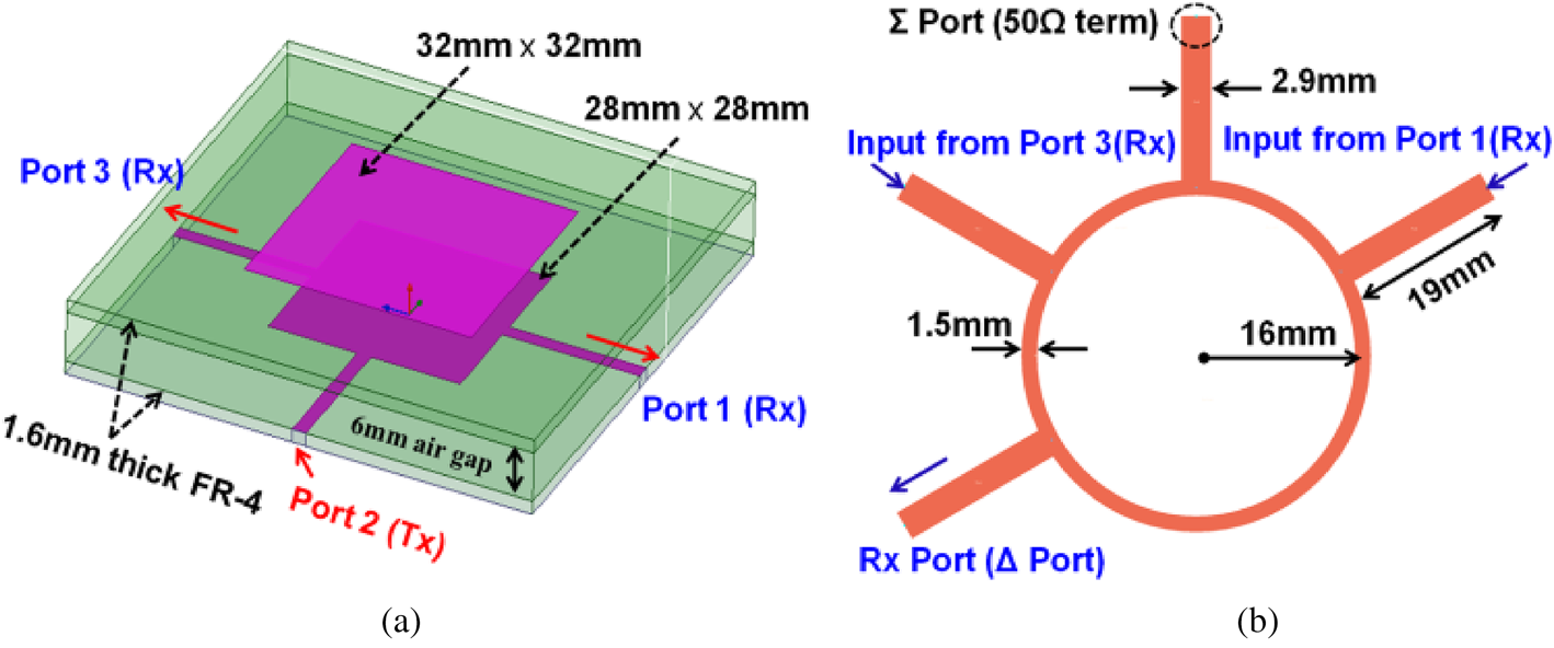
Fig. 1. The layouts of proposed dual polarized, patch antenna (a) three-port parasitic-fed stacked antenna and (b) 2.4 GHz ring hybrid coupler.
The dual-polarized characteristics of the proposed stacked patch antenna are obvious from Fig. 2 as illustrated through simulated surface currents distributions and 3D gain patterns for Tx and differentially-excited Rx modes. The excitation of port 2 generates y-directed polarization for Tx mode and differentially-excited Rx mode is polarized along with the x-axis. These simulation results have been obtained through full-wave simulations by using frequency-domain electromagnetic HFSS solver. The simulated gain patterns are based on spherical theta (θ) and phi (Φ) co-ordinates for variations of theta (θ)-dimensions having fixed values of Φ = 90o and Φ = 0o for Tx and differentially-excited Rx modes, respectively. Moreover, due to the unidirectional radiation characteristics of presented antenna, the theta (θ)-variations of −90o to 90o (upper hemisphere) are recorded only for gain patterns of intended Tx and Rx polarizations as clear from simulation results in Fig. 2.

Fig. 2. The simulated surface current distributions and 3D gain patterns (θ-direction) for Tx mode and differentially-driven Rx mode at f = 2.46 GHz.
The simulated and measured S-parameters for the implemented prototype of three-port parasitic-fed antenna are given in Fig. 3. The measured 10 dB return-loss bandwidth for each port ≥120 MHz as clearly marked in Fig. 3. The cross-polarization features ~ 24 dB interport isolation across the 100 MHz bandwidth for each pair of dual-polarized Tx–Rx ports. The differentially-driven Rx mode through ports 1 and 3 of stacked patch can provide effective SIC operation (S 12–S 32) based on interport currents decoupling ratio (I Tx and I Rx are currents for Tx and Rx ports, respectively):

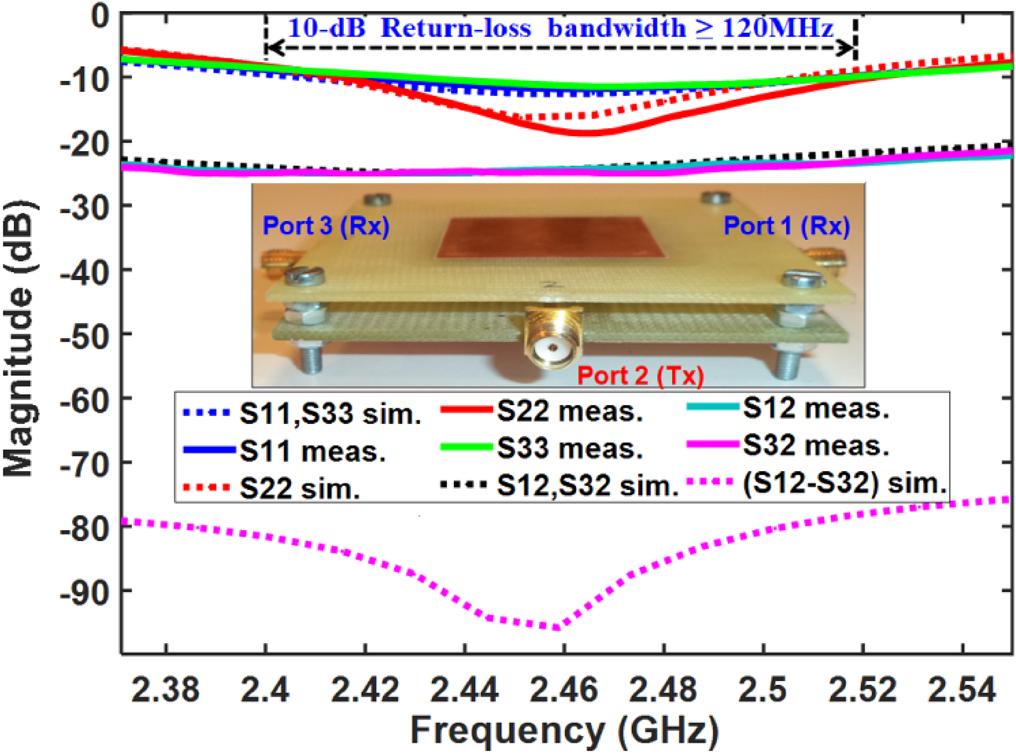
Fig. 3. The simulated and measured S 11, S 22, S 33, and interport coupling (S 12, S 32), (S 12–S 32) results for three-port parasitic-fed stacked patch antenna.
As obvious from (1), the achievable SIC levels are defined by polarization diversity decoupling (S 12 and S 32) and characteristics of the employed differential circuit. For instance, an ideal differential circuit can offer ≥55 dB SIC levels on the top of initial isolation to achieve ~ 80 dB isolation between Tx and differentially-driven Rx port of patch antenna. However, the achieved SIC levels will be degraded when the practical differential circuit is used for differential excitation of Rx mode due to its non-ideal characteristics [Reference Nawaz and Niazi7].
Experimental results for antenna interfaced with ring hybrid coupler
For experimental characterization, the implemented validation model or prototype for the three-port parasitic-fed stacked antenna was interfaced with the prototype of 3 dB/180o ring hybrid coupler (differential circuit) in order to record measurement results. The interconnections are shown in Fig. 4b with designated Tx and Rx ports. The simulation results for comparison purpose were obtained through Keysight advance Design System (ADS) schematic for co-simulation of SIC circuit and three-port antenna as shown in Fig. 4a.
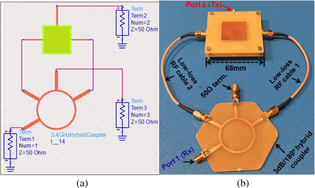
Fig. 4. Keysight ADS simulation schematic and validation model (prototype) of presented antenna for simulated and measured results.
The simulated and measured reflection coefficients (S 11 and S 22) and interport coupling results (S 12) for complete antenna structure (Fig. 4b) are presented in Fig. 5. These measurements were performed inside the anechoic chamber to suppress the propagation domain SI resulting from the environmental reflections. As clear from Fig. 5, the antenna prototype demonstrates 10 dB return-loss impedance of better than 100 MHz spanning over 2.42–2.52 GHz for both Tx and Rx ports. The experimentally characterized isolation levels between dual-polarized Tx and Rx ports are higher than 70 dB over the 100 MHz bandwidth. Moreover, the measured isolation ≥ 80 dB for 40 MHz (from 2.445 to 2.485 GHz) bandwidth. In addition, the recorded peak isolation levels exceed 88 dB as indicated in Fig. 5. Consequently, the differentially-driven Rx operation contributes ≥ 45 dB isolation on top of the polarization diversity isolation.

Fig. 5. The simulated and measured S-parameters results (S 11, S 22, and S 12) for dual polarized, parasitic-fed stacked IBFD patch antenna.
The measured Tx and Rx modes E-plane gain patterns (co. and cross-polarization levels) at f = 2.46 GHz for presented antenna structure (Fig. 4b) are given in Fig. 6. The E-plane gain patterns for implemented antenna were measured in an anechoic chamber through far-field calibrated measurement setup based on 3D spherical dimensions. The implemented antenna or antenna under test (AUT) was used as receiving antenna and a standard horn antenna with known gain was used as transmitting antenna. The AUT was aligned at Φ = 90o and Φ = 0o and θ was varied from −90o to 90o to record the intercepted power through AUT for intended Tx and Rx polarizations, respectively. The gains for both polarizations were determined through comparison method to plot the results. These measurements demonstrate peak gain levels of better than 7.0 dBi for both modes. The comparative improved gain performance of presented antenna is due to employed parasitic feeding for both Tx and Rx modes. The cross-polarization levels are below −33 and −47 dB for Tx and Rx ports, respectively.
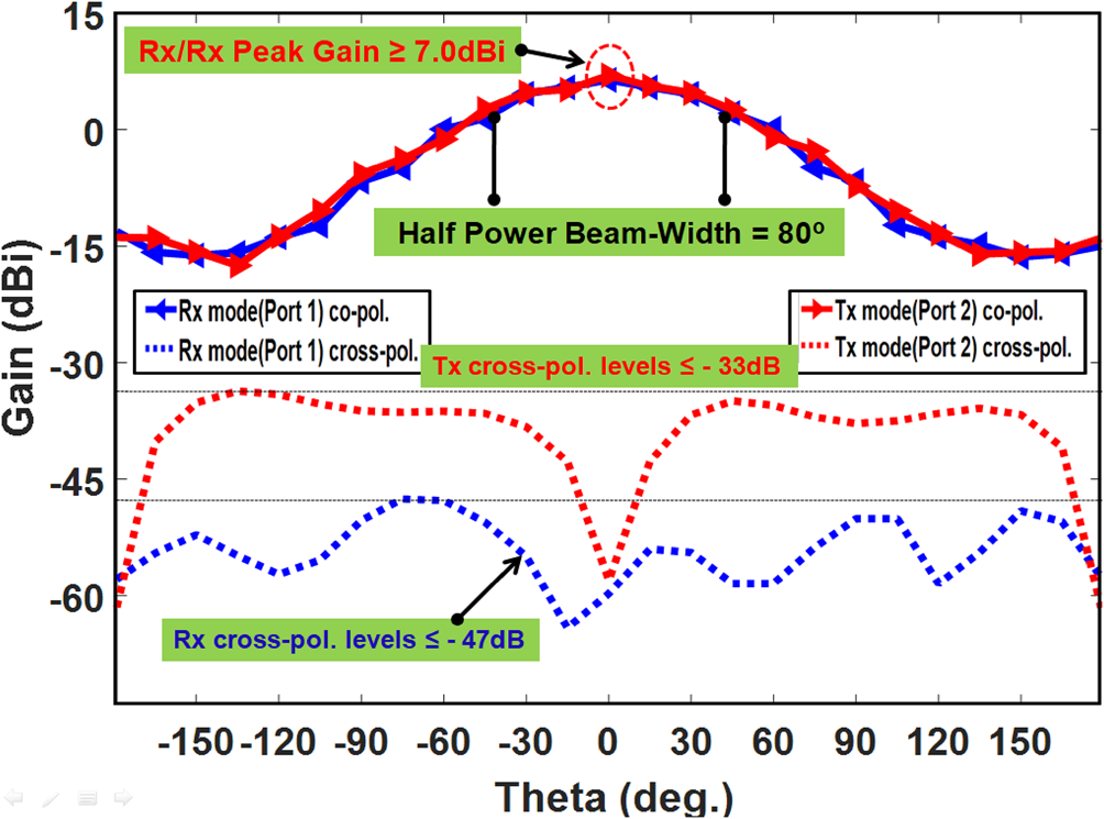
Fig. 6. The experimental co-polarization and cross-polarization E-plane gain patterns at 2.46 GHz for implemented parasitic-fed patch antenna.
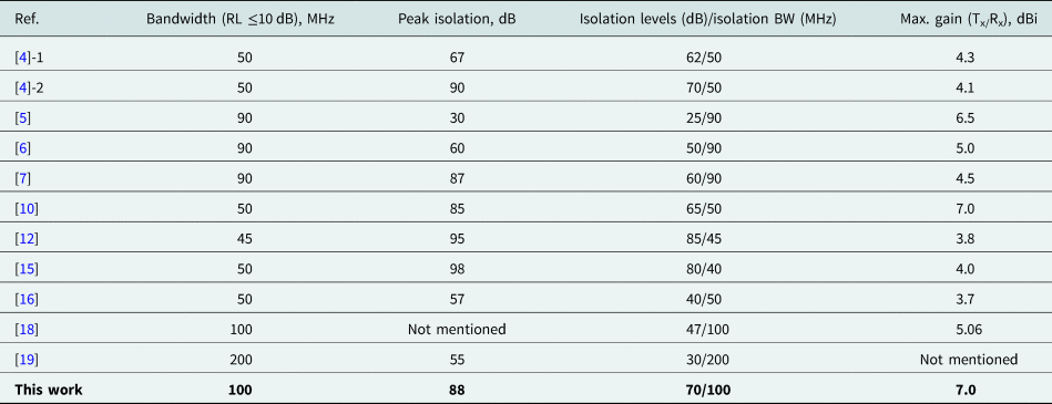
The performance comparison of presented differentially-fed stacked patch antenna with previously reported 2.4 GHz IBFD antennas is presented in Table 1. This comparison table provides the comparison of 10 dB return-loss bandwidth, peak (highest) isolation levels, isolation levels versus isolation bandwidth, and maximum Tx/Rx gain for reported dual-polarized IBFD antenna designs. As clear from Table 1, the presented antenna provides wider impedance bandwidth (100 MHz), very high peak isolation (88 dB), and improved isolation levels versus isolation bandwidth (70 dB over 100 MHz bandwidth) performance along with the superior gain performance as compared to previously reported antennas. The contributions of this work are the realization of a single-element based antenna with wider impedance bandwidth and high gains for both Tx and Rx polarizations along with the characteristics of high interport isolation over a wider bandwidth.
Table 1. The performance comparison of presented differential-fed stacked patch antenna with other IBFD antennas.
Conclusion
A dual polarized, stacked antenna with parasitic feeding is presented to demonstrate wider impedance bandwidth, high gain and excellent interport isolation through differential Rx operation. The presented antenna features wider impedance bandwidth, improved interport isolation characteristics and superior gain performance compared to previously reported antennas. The measured peak radiation efficiency for presented antenna was better than 75%. More compact antenna structure can be realized through placement of ring coupler (SIC circuit) on the backside of the driven patch with via-interconnections to both Rx ports. The implemented antenna can be used for 2.4 GHz transceiver to realize full-duplex operation over the 100 MHz bandwidth without additional and complex analog domain SIC topologies.
 Haq Nawaz received the B.Sc. degree in Electrical Engineering and the master's degree in Telecommunication Engineering from the University of Engineering and Technology (UET), Taxila, Pakistan, in 2005 and 2012, respectively. He received the Ph.D. degree in Electronic Engineering from the Sabanci University, Istanbul, Turkey. From January, 2017 to June, 2018, he has worked as a post-doc research fellow with Faculty of Engineering and Natural Sciences (FENS), Sabanci University, Turkey. During 2006–2009, he was with SUPARCO Pakistan as an RF Design Engineer. He served UET Taxila, Sub-Campus Chakwal, Pakistan, as a lecturer in Electronics Engineering from 2010 to 2012.
Currently, he is working as an assistant professor at Department of Electronics Engineering, UET Taxila, Sub-Campus Chakwal, Pakistan. His research interests include full duplex antenna design, RF circuits design and measurements for Radar and Satellite systems, beam-switched and phased scanning array antennas design and indoor positioning systems design.
 Ahmad Umar Niazi received the B.Sc. degree in Electrical Engineering with specialization in Communication & Electronics from the University of Engineering & Technology (UET), Lahore, Pakistan and the Master's degree in Electrical Engineering Department from the University of Engineering and Technology (UET), Taxila, Pakistan, in 2001 and 2012, respectively. He is now pursuing his Ph.D. degree in Electrical Engineering Department from UET Taxila, Pakistan. He served at private and public sector industries/organizations from 2001 to 2006. He joined UET Taxila, Sub-Campus Chakwal, Pakistan, and served as a lecturer in Electronics Engineering Department from 2007 to 2012.
Since 2012, he is working as an assistant professor at Department of Electronics Engineering, UET Taxila, Sub-Campus Chakwal, Pakistan. His research interests include microwave antenna design, antennas for 5 G applications, full-duplex antenna design, RF circuits design, beam-switched and phased scanning array antennas and multi-band jamming techniques.


