


Introduction
In modern microwave systems, a high-power microwave (HPM) antenna is necessary to efficiently transmit high-power signals from the HPM source to the target. In HPM systems, HPM sources are used to generate high-power pulses for a very short duration [Reference Reddy and Sambasivarao1]. These high-power pulse signals are transmitted or radiated through a mode converter and horn antenna [Reference Schamiloglu2]. Many other types of antennas have also been designed, e.g. the helical antenna [Reference Liang, Zhang, Liu and Li3], TEM horn antenna [Reference Wang and Xie4], impulse radiating antenna [Reference Xiao, Altunc, Kumar, Baum and Schoenbach5] to radiate microwave signals. But all these antennas support polarization operation linearly. These antennas (linearly polarized) cannot efficiently deliver the power if they are not appropriately aligned with the target. A circularly polarized (CP) antenna must be designed to radiate HPM signals to avoid this issue. Several methods have been proposed to convert linearly polarized waves to CP waves, e.g. waveguide mode converter [Reference Yuan and Zhong6, Reference Li, Deng, Guo, Huang and Shao7], metasurfaces [Reference Li, Liu, Cheng, Chen and Tian8–Reference Baena, del Risco, Slobozhanyuk, Glybovski and Belov10], various types of slots [Reference Shi, Shi, Li, Nie, Guan and Cui11, Reference Wang, Wu and Shen12], meander line [Reference Joyal and Laurin13, Reference Fei, Shen, Wen and Nian14], and grating structures [Reference Mutlu, Akosman and Ozbay15–Reference Wang, Shen, Wu and Feng17]. The conventional polarizer (CP type) generally accepts TE11 mode as input [Reference Kirilenko, Steshenko, Derkach and Ostryzhnyi18], and they are not convenient with higher-order input mode. HPM systems produce output as TM01 mode [Reference Benford, Swegle and Schamiloglu19]. Many mode converters have been presented to provide CP TE11 mode [Reference Sun, He, Yuan and Zhang20–Reference Chittora and Yadav22], but all reported converters are not compact enough. Besides this, only a few CP antenna designs are reported for HPM systems. Therefore, there is scope for the improvement of compactness of the polarizer excited with higher-order mode.
Many microwave lens forms are reported, such as Fresnel lenses, for instance, and dielectric lenses, but the advantages of metal plate lens are light in weight, low cost, and easy to build and compact as compared to other ones.
So in this contribution, we designed an antenna, which performs mode conversion (TM01 to CP TE11 mode) as well as transmission of the signal. This article aims at developing a CP high-power antenna with higher-order mode excitation. The designed antenna exhibits high gain and radiation efficiency with excellent power handling capability. Four sections are discussed in this paper. In “Design principle and structure” section, the high-power antenna's design principle and geometrical details are explained. In “Results and discussion” section, the simulated and measured results of the antenna are presented. Conclusions are summarized in the last section.
Design principle and structure
The high-power antenna is used for several applications like airborne, portable HPM operation, material's electric characterization, and so on. The main design parameters of the HPM antenna are high-power capability, gain, radiation pattern, and reflection coefficient (S 11). The designed structure should be low profile, efficient, and easy to fabricate. Therefore to achieve all these characteristics, we developed an antenna based on a mode conversion process.
The proposed structure consists of metal plates placed on the horn antenna's aperture to produce CP TE11 mode at the output. Here, the conical horn antenna is used as a radiator, which exhibits high gain and radiation efficiency, and it also supports circular polarization.
In this paper, the input power is in the form of the TM01 mode of the conical horn antenna, as shown in Fig. 1. In a circular waveguide, TM01 mode is the first higher-order mode. This mode field pattern consists of radially diverging E-field lines. The direct radiation of TM01 mode through the antenna produces a divergent beam; this results in minimum power at the center. For efficient radiation, there must be maximum power at the center.
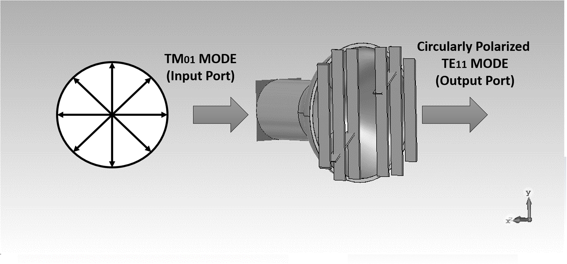
Fig. 1. Generation of circularly polarized output from higher mode excitation.
For avoiding this issue, a CP antenna must be designed to radiate HPM signals. Therefore, we designed a metal plate structure, which converts the TM01 mode into CP TE11 mode. Here, the metal plate structure consists of seven vertical plates. All plates have the same thickness, and the gap between the two plates is also the same. Initially, the dimensions of each metallic rectangular vertical plate are 20 × 2 cm2. Spacing between two consecutive metal plates is 3 cm, as shown in Fig. 2(a). After that, the center metallic rectangular plate is placed at an angle of +45° from the yz-plane (with a small cut from the center) to produce left-handed circular polarization (LHCP) output. If placed at an angle of −45°, right-handed circular polarization output will be provided, as shown in Fig. 2(b).

Fig. 2. The layout of the proposed structure.
Once the optimum dimension plate structure is appropriately designed, we can place it on the conical horn antenna's aperture to get the CP TE11 at the output. Figure 2 shows the layout of the proposed antenna.
The proposed structure composed of a set of parallel metal plates, and it can be divided into an E-plane or an H-field. Here, one plane (E-plane) works as an accelerating plane, and the other lens works as a delay plane. Here, it is noticed that when the electromagnetic (EM) wave travels in an E-plane, the phase velocity (Vg) is higher than the phase velocity (V 0) in the free space. Similarly, when the EM wave travels in the H-plane, the phase velocity (vg) is less than the phase velocity (V 0) in the free space [Reference Jiao, Pan, Jin and Xiong23]. It ensures that we can obtain or achieve the desired phase distribution of the EM wave by adjusting the gap between the two metal plates and the two metal plate width. In this letter, for excitation of TM01 mode at the horn's input port, a TM01 mode feed is designed to make a conical monopole and an inverted cone, as shown in Fig. 5. The designed feed converts coaxial-TEM mode to TM01 mode. The designed TM01 mode feed is applied at the conical horn antenna's input port. The output TE11 mode can be divided into vertical polarization and horizontal polarization. Each orthogonally polarized components (horizontal or vertical) have equal amplitudes but out of phase (by 90°), which is essential for circular polarization.
Results and discussion
The proposed high-power antenna is designed and simulated using CST Microwave Studio. Here, the conical horn antenna is used as a polarizer as well as a radiator, which exhibits high gain and radiation efficiency. The proposed antenna is designed at 3 GHz frequency. A metallic plane sheet of thickness 0.2 cm is used to design a proposed polarizer. The optimized parameter values for metal plate structure are length = 20 cm and width = 2 cm.
Figure 3 shows the center metal plate's effect at an angle of +45° (with a small cut from the center) to produce LHCP output. This figure shows how this center plate improves the performance of the proposed structure. Figure 3 shows that at an angle of 35°, the axial ratio is 3 dB (at the operating frequency). When we increase the angle by 10° (i.e. 45°), the axial ratio is below 3 dB (~1 dB). Further increasing the angle by 10° (i.e. 55°), the axial ratio increases to 14 dB (at the operating frequency). This figure ensures that at an angle of 45°, the axial ratio is below 3 dB over the frequency band 2.97–3.10 GHz.

Fig. 3. Axial ratio versus frequency plot of the proposed high-power antenna.
The gain is an important design parameter for any high-power directive antenna. It also shows how strong a signal of an antenna can be radiated or received in a specific direction. Besides, a high-gain antenna will radiate maximal power in a particular direction. The proposed antenna has a high gain of up to 13.4 dB at 3 GHz frequency, as shown in Fig. 4.

Fig. 4. Simulated and measured radiation patterns at 3 GHz with higher mode excitation (TM01) at input port.
The mode conversion (TM01 mode to circular polarized TE11 mode) can be verified from the measured radiation pattern. The simulated and measured radiation pattern at 3 GHz is plotted and shown in Fig. 4. The radiation pattern measurement is performed by exciting the TM01 mode at an antenna's input port in an anechoic chamber, as shown in Fig. 5. Due to mode conversion (TM01 to CP TE11), the radiation pattern becomes maximum at the boresight with a metal plate structure. The reflection coefficient (S 11) is also measured using vector network analyzer and measured results compared with the simulated one. Figure 6 shows the simulated and measured S-parameter (S 11) for an antenna. Both curves are in good agreement.

Fig. 5. High-power antenna testing and measurement setup in an anechoic chamber.

Fig. 6. Comparison of measured and simulated S-parameters.
The power-handling capability of the HPM antenna is also calculated by simulation. Generally, the breakdown would be different for different vacuum conditions. The metal electric field breakdown strength is about 1 MV/m [Reference Xiao, Chen, Sun, Zhang and Zhang24]. This paper considers the maximum electric field limit as 3 MV/m for the breakdown. Here, the maximum E-field remains below 1584 V/m for a maximum of 0.5 W input power. Therefore, the proposed antenna can handle a high power of up to 1.8 MW. The electric field strength will be increased three times greater than that of air if we use SF6 gas fixed outside the aperture to prevent air breakdown [Reference Chang, Zhu, Liu, Fang, Xiao, Chen, Shao, Li, Huang, Zhang and Zhang25]. Since only metal plates are used in the structure, it shows a compact, very lightweight, and low-cost solution for CP HPM antenna design.
Table 1 shows a comparison between the proposed design and earlier published mode converter designs. Earlier presented converters have also been designed to radiate microwave signals, but all these structures support TEM to CP TE11 operation [Reference Sun, He, Yuan and Zhang20, Reference Yuan, Zhong, Liu and Qian26, Reference Wang, Fan, Shu, Yuan and Zhang27]. The design proposed in [Reference Yuan, Zhong, Liu and Qian28] supports TM01 to CP TE11 process, but high-power capability is not discussed in the paper. The proposed work aims to design a compact size CP high-power antenna, HPM antenna, that can convert the TM01 input signal to CP TE11 output. The designed antenna exhibits high gain, power capability and is very compact compared to other designs.
Table 1. Comparison between the proposed design and earlier published mode converter designs

Conclusion
In conclusion, a CP high-power antenna with higher-order mode excitation is presented in this paper. The proposed antenna converts the TM01 input signal to the CP TE11 output. This structure also receives a directive radiation pattern. The measured radiation patterns are in agreement with the simulated results. The calculated electric field shows that the designed antenna can handle a high-power input signal. The designed antenna is compact and lightweight, and easy to fabricate. Therefore, it is suitable for airborne and portable HPM systems and space applications.
 Swati Varun Yadav received her B.E. degree in Electronics and Communication Engineering from MIT, Ujjain (India) in 2007 and received his M.E. degree in Digital Communication from Rajiv Gandhi Proudyogiki Vishwavidyalaya, Bhopal (India) in 2011. She has been pursuing her Ph.D. degree in the Electrical and Electronics Engineering Department at BITS Pilani, K K Birla Goa Campus (India) since 2019. Her fields of interest are high-power microwave passive devices and antennas.
 Ashish Chittora received his B.E. degree in Electronics and Communication Engineering from Engineering College, Kota, India, in 2009, M.E. in Electronics and Communication Engineering from Delhi College of Engineering, Delhi, India, and Ph.D. in Electrical Engineering from I.I.T. Bombay, Mumbai, India in 2016. He worked at Amity University, Noida, India as an Assistant Professor. Currently, he is Assistant Professor in the Electrical and Electronics Engineering Department at BITS Pilani, K K Birla Goa Campus. His research interests include high-power microwave passive devices and antennas.


