I. INTRODUCTION
Frequency selective surface (FSS) is an array of periodically arranged metallic patches or slots printed on the dielectric substrate, which can be thought of spatial microwave filters with transfer functions defined in three-dimensional space (frequency, angle-of-incidence (AOI), and polarization of the incident wave) and used for various applications such as dichroic mirrors in large reflection antennas for radio-astronomy/satellite communication systems, spatial filtering/shielding, design of radomes, and wireless security [Reference Munk1, Reference Wu2]. However, unlike the microwave filters, the frequency response of the FSS structures is not only the function of frequency but also the function of AOI and polarization of the electromagnetic (EM) wave. Earlier, various topologies of the FSS structures have been designed and analyzed, which are used in one or another form as the spatial filters to improve the purity of the incident wave in the communication systems [Reference Cahill and Parker3].
Recently, the demand of miniaturized FSS structures has been increased because such type of structures avoids the high-order resonance frequencies, which are undesirable in various applications [Reference Zhang, Yin and Ma4–Reference Guohui, Zhang, Wanlu and Wu6]. Apart from the miniaturization, the angular stability of FSS structure is also very important parameter which has to be satisfied over the wide range of the operating AOI. The angular stability of FSS structure is improved with the reduction in the size of unit-cell and this concept has been used for designing the miniaturized structure [Reference Sung7]. In addition to the angular stability, the bandwidth of the structure is also increased with the reduction in the periodicity of the unit-cell [Reference Munk8]. On this way, the unit-cell size has been used to control the angular stability and the bandwidth of the structure. Among the existing topologies, the classical circular ring FSS structure is the most appropriate angular stable structure [Reference Munk1]. However, there are several approaches for the analysis of the FSS structure such as modal (method-of-moment), equivalent circuit (EC), and iterative approach [Reference Tsao and Mittra9].
In this paper, we have employed the EC approach for the numerical analysis of inductive and capacitive behavior of the conducting circular loop as well as gap between the two adjacent loops and the equivalent lumped parameters of the proposed FSS structure is obtained. The analysis of FSS structure depends on the geometrical parameters like periodicity (p) of the loop, loop dimension (d), width of the loop strip (w) and gap between the two adjacent loops (g). Recently, in the present paper, we have reported a novel synthesis technique for single square loop FSS (SSLFSS) [Reference Jha, Singh and Jyoti10], which has been extended to obtain the geometrical parameters of the proposed modified circular ring FSS structure. In addition to this, the effect of the wide range of AOI as well as perpendicular and parallel polarized wave over the reflection/transmission frequency response has been discussed. The remainder of paper is organized as follows. Section II discusses the generalized simple synthesis approach, which provides the optimized geometrical parameters of the SSLFSS structure and reduces the number of iterations in order to achieve the desired frequency response. Section III discusses the problem statement regarding the classical FSS structures (square loop and circular ring) and explores the need to propose a modified circular ring FSS structure. Section IV discusses the numerical analysis of the proposed modified circular ring FSS structure. Section V discusses and compares the simulation results of the proposed FSS structure through different techniques such as finite element and finite integral with the results obtained through numerical analysis. The angular stability and the bandwidth control of the proposed modified circular ring FSS structure have been discussed in Section VI. Section VII discusses the measured frequency response. Finally, Section VIII concludes the work.
II. GENERALIZED SYNTHESIS APPROACH
We have analyzed the proposed modified circular ring FSS structure through EC technique among various numerical techniques because it provides simpler, rapid, and accurate frequency response. We have discussed the synthesis technique to achieve the geometrical parameters of the SSLFSS structure, which has been shown in Fig. 1.

Fig. 1. The generalized synthesis approach for the SSLFSS structure.
In the synthesis approach, the width of conducting strip and inter-element gap has been interpreted in terms of its EC and provide the normalized mathematical expressions of its associated inductance and capacitance [Reference Bahl11]. On the multiplication of these two normalized mathematical equations shown in block 4 of Fig. 1, we have achieved the resonance criteria. In addition to this, ideally for the reflective FSS structure, the value of the ω r 2LC must be equal to unity at the resonance frequency (ω r 2 = 1/LC) therefore, the expression for the resonant criteria has been modified as shown in Fig. 1. To simplify the synthesis technique of the FSS structure, we have considered the loosely packed array of FSS structure with negligible width of the conducting patch (w) of the unit-cell element and inter-element gap (g) between the unit-cell elements as compared with twice of the periodicity (p). We have obtained the geometrical parameters (p, w, d) of the SSLFSS unit-cell through this synthesis technique for S-band, which are as follows: p = 85.02 mm, d = 25.02 mm, and w = 1 mm. In this entire synthesis, we have also considered the effect of the dielectric substrate, therefore, the right hand side of the equation shown in block 8 of Fig. 1 is multiplied by the effective dielectric permittivity. The geometrical parameters obtained through the generalized synthesis approach have been validated through the commercially available simulators such as CST Microwave Studio as well as Ansoft HFSS and results are comparable in terms of the frequency response.
III. PROBLEM FORMULATION
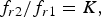
In Section II, we have discussed a simple synthesis technique, which has been used to obtain the geometrical parameters of the SSLFSS structure. However, the angular as well as polarization stability is the prime issue of the FSS structures, which needs to be discussed for this proposed model. The circular ring FSS structure is more angular stable as compared with the square loop FSS structure due to the rotational symmetry [Reference Munk1]. Therefore, we have performed the structure transformation and designed the circular ring FSS structure for the same values of the periodicity (p), loop size (d), and width of the conducting strip (w), which have been obtained through the synthesis technique of the SSLFSS structure. For the same value of the p, d, and w, the resonance frequency of single square loop and circular ring FSS structures are related as follows.
 $${P_{SL}}/{C_{Cir}} = K\comma \; $$
 $${f_{r2}}/{f_{r1}} = K\comma \; $$
where P SL , CCir, fr 1, and f r2 are the perimeter of the single square loop, circumference of the circular ring, resonance frequency of the single square loop, and resonance frequency of the circular ring FSS structure, respectively. From equations (1) and (2), it is illustrated that the resonance frequency of classical circular ring FSS structure is greater than that of SSLFSS structure, which has also been validated through commercial simulators such as CST Microwave Studio and Ansoft HFSS as discussed in [Reference Bharti, Jha, Singh and Jyoti12] because for the same values of the p, w, and d, the circumference of the circular ring unit-cell is small as compared with the perimeter of the square loop unit-cell FSS structure. In addition to this, the ratio of perimeter of square loop (P SL ) to the circumference of circular ring (C cir ) is approximately equal to the ratio of the resonant frequency of the circular ring to that of the square loop. Moreover, for the square loop FSS array, the effect of the inter-element gap capacitance is more significant in comparison with that of the circular ring FSS as the distance between the adjacent loops (g = m) in square loop FSS array is always fixed (shown in Fig. 2(a)), whereas in the circular ring FSS array, the distance between adjacent cells (g = m) increases when moves between ±90° with respect to the line crossing the 0° through the center (shown in Fig. 2(b)). In other words, the resonance frequency of the classical circular ring FSS structure mainly depends upon its inductance. For the significant implementation of the synthesis technique, we need to reduce the resonance frequency of a circular ring FSS structure up to the desired value, which is equal to that of the SSLFSS structure, which has been achieved through increasing the size of circular ring FSS structure. However, with the increase of the effective size of the circular ring FSS, the value of periodicity (p) need to be increased, which reduces the angular stability of the structure and affects its miniaturization [Reference Sung7].

Fig. 2. The array of (a) single square loop and (b) classical circular ring FSS structure.
To control this limitation and to achieve better angular stability as compared with other reported structures [Reference Sung7, Reference Sung, Sowerby and Williamson13–Reference Hosseinipanah, Wu, Zhang, Minji and Yang16], the classical circular ring FSS has been modified into the proposed modified circular ring FSS structure as shown in Fig. 3 with the same values of p, d, and w as that of the SSLFSS structure. The proposed modified circular ring FSS structure consists of metallic patch of the aluminum foil with electrical conductivity (σ) = 3.8 × 10⁷ S/m as well as magnetic permeability (μ) = 1.2566 × 10⁻⁶ H/m and is placed on the Teflon substrate with relative dielectric permittivity 2.1 and loss tangent (δ) 0.002. The thickness of dielectric substrate (h) and metallic conductor (t) for S-band has been computed, which is 10.00 and 0.01 mm, respectively. However, to reduce the resonance frequency, the four pairs of parallel straight conductors have been incorporated in the classical circular ring FSS as shown in Fig. 3.

Fig. 3. The proposed modified circular ring FSS structure.
IV. NUMERICAL ANALYSIS OF PROPOSED MODIFIED CIRCULAR RING FSS
For the classical circular ring FSS structure, the value of inductance is given as [Reference Bahl11]:
 $${L_1}(nH) = 1.257 \times {10^{ - 6}}.a\left[ {\ln \left( {\displaystyle{a \over {w + t}}} \right) + 0.078} \right].{K_g}\comma \; $$
where a is the mean-radius of circular ring, w is the width of the conducting strip, t is the thickness of the conducting strip and K g is the correction factor, which indicates the height of the substrate from the ground plane. In general, equation (3) is used to obtain the value of the microstrip inductance above the grounded substrate and on the other hand, in FSS structures, the ground plane beneath the substrate is not used. Therefore, the correction factor K g which provides the effect of the electric field between the microstrip structure and the ground plane, is set equal to the unity [Reference Bahl11]. In addition to this, the capacitance of the classical circular ring FSS structure is given as:
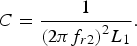 $$C = \displaystyle{1 \over {{{(2\pi {f_{r2}})}^2}{L_1}}}.$$
In equation (4), C is the capacitance of the unit-cell of the classical circular ring FSS structure. For a classical circular ring FSS structure, the value of f r2 is obtained using equations (1)−(2) and the value of C is extracted by substituting the value of L 1 from equation (3) into (4). As, it has already been discussed that the values of p, w, and d are same in both the FSS structures (classical circular ring and proposed modified circular ring), which indicates that the gap capacitance is approximately same and the value of C obtained using equation (4) has also been used as the gap capacitance of the proposed modified circular ring FSS structure as shown in Fig. 3. Further, the downshift in the resonance frequency of the FSS structure as shown in Fig. 3 is controlled by varying the value of l (internally extended length of the parallel straight conductor), which influence the total inductance of the proposed modified circular ring FSS structure with its associated inductance L 2, which is given as:
 $${L_2}(nH) = 4 \times {10^{ - 4}}l\left[ {\ln \left( {\displaystyle{l \over {w + t}}} \right) + 1.193 + 0.333\left( {\displaystyle{{w + t} \over l}} \right)} \right]{K_g}$$
Therefore, the total inductance (L) of the proposed modified circular ring FSS structure is the sum of L 1 and L 2. For any value of l except zero, L > L 1 and the resonance frequency of the proposed modified circular ring FSS structure is decreased without affecting the other parameters and it is given as:
 $${f_{MR}} = \displaystyle{1 \over {2\pi \sqrt {LC}}}\comma \; $$
where L = L 1 + L 2 and f MR is the resonance frequency of the proposed modified circular ring FSS structure. With the decrease in resonance frequency, the wavelength λ in comparison with l = 0 is increased and due to the ratio of period-to-the wavelength (p/λ) is decreased and the angular stability of the FSS has been increased [Reference Munk1].
V. FREQUENCY RESPONSE OF MODIFIED CIRCULAR RING FSS STRUCTURE
To examine the proposed synthesis technique, and to meet the specific requirement of resonance frequency at 3 GHz, the proposed FSS structure has been analyzed through EC technique and simulated through CST Microwave Studio as well as Ansoft HFSS in this section. At 3 GHz, the values of p, d, and w are 85.02, 25.02, and 1 mm, respectively, for the SSLFSS structure which has been obtained through the generalized synthesis approach discussed in Section II. Further, in order to avoid the grating lobes in the desired operating frequency band, the periodicity is considered as half of the free-space wavelength at the frequency of operation. Therefore, the geometrical parameters of the SSLFSS structure at 3 GHz are computed as: p = 42.51 mm, d = 25.02 mm, and w = 1 mm. Using these geometrical parameters, the circular ring FSS structure resonate at 3.69, 3.672, and 3.70 GHz through analytically, CST Microwave Studio and Ansoft HFSS, respectively, which justified the theory discussed in Section III. However, for the implementation of the synthesis technique on the circular ring FSS structure, the structure must resonate at the same frequency as that of the SSLFSS structure, which has been achieved through increasing the dimensions such as periodicity and loop size of the circular ring FSS structure.
With the increase in the value of periodicity, the angular sensitivity and compactness of the FSS structure is affected [Reference Munk1]. As in the entire analysis, we have assumed that the value of capacitance approximately remain same, which has been obtained using equation (4). Therefore, to resonate the classical circular ring FSS structure at lower frequency such as at 3 GHz without changing the periodicity and loop size, there is need to increase the value of inductance, which is achieved through the proposed modified circular ring FSS structure as shown in Fig. 3. When l = 0, the proposed FSS structure is represented as a classical circular ring FSS structure and in this case, the associated inductance L 1 and capacitance (C) is obtained using equations (3) and (4), respectively as well as the value of resonance frequency has been computed through equations (1) and (2). In this case, the analytical value of the resonance frequency is 3.69 GHz and the corresponding value of the inductance L 1 and capacitance (C) is 38.49 nH and 48.38 fF, respectively.
For any other values (except zero) of l, the inductance L 2 associated with the internally extended length of the four pairs of parallel straight conductors is obtained using equation (5) and on this way the total inductance L is the sum of L 1 and L 2, and the resonance frequency is obtained by equation (6). For different values of l, the values of total inductance L and C have been analytically computed as shown in Table 1. Further, with the increase of the l as shown in Fig. 3, the resonance frequency shifts towards the intended frequency. The frequency response of the S-parameters, which is obtained through CST Microwave Studio and Ansoft HFSS for the proposed FSS structure as shown in Fig. 3, has been demonstrated in Figs 4(a) and 4(b), respectively.

Fig. 4. The simulated frequency response of proposed structure as predicted in Fig. 3 over the transmission and reflection coefficients for various values of l using the (a) CST Microwave Studio and (b) Ansoft HFSS.
Table 1. The effect of l on the resonant frequency at 3 GHz of the proposed FSS structure.

Further, the proposed FSS structure has been simulated using CST Microwave Studio and Ansoft HFSS, which are based on the finite integral technique and finite element method to support the analytical frequency response at normal incidence of EM wave as shown in Figs 4(a) and 4(b), respectively. Table 1 and Fig. 4 have demonstrated that the proposed modified circular ring FSS structure with internally extended length (l) = 5.6 mm provides close agreement with the intended frequency in terms of the reflection as well as transmission frequency response. Therefore, the geometrical parameters of the proposed modified circular ring FSS structure at 3 GHz are obtained as: p = 42.51 mm, d = 25.02 mm, w = 1 mm, and l = 5.6 mm.
VI. ANGULAR AND POLARIZATION STABILITY OF MODIFIED FSS STRUCTURE
Due to the internal elongation of length (l) in the proposed FSS structure as shown in Fig. 3, the resonance frequency as well as p/λ is reduced which significantly enhance the angular stability of the structure. To illustrate this effect, the proposed modified circular ring FSS structure with length (l) = 5.6 mm is clear from Table 1, which has been simulated for the perpendicular as well as parallel polarized wave incidence up to 50° AOI. However, the polarization effect on the performance of proposed FSS structure through CST Microwave Studio and Ansoft HFSS has been shown in Figs 5(a) and 5(b), respectively.

Fig. 5. The simulated reflection/transmission frequency response of the proposed FSS structure for perpendicular polarized wave incident at different AOI using (a) CST Microwave Studio and (b) Ansoft HFSS.
For the perpendicular polarized wave incidence up to 50°, the resonance frequency downshift with 3.30 and 3.00% with reference to the normal incidence, which is achieved using CST Microwave Studio (shown in Fig. 5(a)) and Ansoft HFSS (shown in Fig. 5(b)), respectively. This angular stability has been achieved by considering the smaller value of the periodicity as well as appropriate dielectric profile for the FSS structure, which provide the significant effect on the associated L and C. In addition to this, the percentage decrease in 3-dB reflection as well as transmission bandwidth for perpendicular polarized wave incidence up to 50° is 3.15% (shown in Fig. 5(a)) and 3.28% (shown in Fig. 5(b)) using CST Microwave Studio and Ansoft HFSS, respectively as compared with that of the normal incidence. Further, the fractional bandwidth (FBW) of the proposed FSS structure for 0°, 10°, 30°, and 50° are 28.87, 28.47, 28.45, and 28.91%, respectively, through CST Microwave Studio and 29, 28.95, 28.79, and 28.94%, respectively, through the Ansoft HFSS. It is important to note that the FBW is greater than 28% even at the 50° of AOI.
Moreover, for the parallel polarized wave incidence up to 50°, the 1.07 and 0.66% downshift in the resonant frequency has been achieved through CST Microwave Studio (shown in Fig. 6(a)) and Ansoft HFSS (shown in Fig. 6(b)), respectively as compared with that of the normal incidence. In addition to this, the percentage decrease in 3-dB reflection as well as transmission bandwidth for parallel polarized wave incidence normally and at 50° AOI is 3.21 and 2.64% using CST Microwave Studio and Ansoft HFSS, respectively. Further, the FBW of the proposed FSS structure for 0°, 10°, 30°, and 50° are 23.73, 23.41, 23.00, and 23.24%, respectively, with CST Microwave Studio and 23.98, 24.0, 23.82, and 23.52%, with Ansoft HFSS, respectively. From the EC point of view, the proposed modified circular ring FSS structure as shown in Fig. 3 has been represented by a single series LC circuit, which is shunted across a transmission line of impedance Z o , where Z o is the characteristic impedance of free-space and is equal to the 377 Ω. However, with the increase of the AOI as 0°, 10°, 30°, and 50°, the value of inductance decreases as 55.45, 54.60, 48.02, and 35.64 nH, respectively, due to increase in the value of Z o which results the increase in the out-of-band rejection level and decreases the 3-dB reflection as well as transmission bandwidth and provides the narrow bandwidth as shown in Figs 5 and 6. In addition to this, Figs 5 and 6 have demonstrated that compared with the perpendicular polarization there is significantly small variations in the frequency response characteristics of the parallel polarization because it lies on the symmetrical configuration of the FSS structure. Moreover, the percentage deviation of the resonant frequency of the proposed modified FSS structure is compared with that of the other reported literature as illustrated in Table 2.

Fig. 6. The simulated reflection/transmission frequency response of the proposed FSS structure for parallel polarized wave incident at different AOI using (a) CST Microwave Studio and (b) Ansoft HFSS.
Table 2. Comparison of the percentage frequency deviation of the proposed FSS structure with that of other reported literature.

VII. EXPERIMENTAL VALIDATION
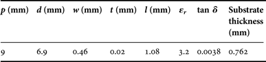
To validate the synthesis technique, based on the available infrastructure, the proposed modified circular ring bandpass FSS structure in X-band has been fabricated and tested. The free space measurement setup with the two X-band horn antennas, which are used as reference antennas, has been shown in Fig. 7. The FSS structure fabricated on a single sided copper clad substrate of 18 × 18 cm2 (using the conventional chemical processing) is placed between the two X-band horn antennas and illuminated with the plane waves generated by the transmitting horn antenna, which is normal to the FSS structure. A distance of 50 cm between the horn antennas and FSS structure is fixed to guarantee the operation in the far-field region [Reference Bayatpur and Sarabandi17, Reference Jang, Kang and Kim18]. The transmitted waves through the FSS structure have been collected by the receiving horn antenna and the vector network analyzer (VNA) is used to measure the reflection as well as transmission characteristics. The structure parameters (in mm) are given in Table 3, which has been obtained using the proposed synthesis technique.

Fig. 7. The schematic of the experimental setup using VNA.
Table 3. The geometrical parameters of the proposed FSS structure at 10.50 GHz.

For the comparison, the proposed FSS structure has been simulated in CST Microwave Studio and Ansoft HFSS in 8–12.5 GHz range and the measured as well as simulated response is shown in Fig. 8. From Fig. 8, it is observed that the proposed FSS structure resonates at 10.691 and 10.70 GHz through CST Microwave Studio and Ansoft HFSS, whereas in the measured result it resonates at 10.69 GHz, which provides the significantly comparable frequency response and demonstrates the practicality of the proposed FSS structure. Moreover, in the simulation, the −10 dB impedance bandwidth extends from 10.094 to 11.081 GHz and 10.229 to 11.18 GHz through CST Microwave Studio and Ansoft HFSS, respectively against the measured value of 10.37–10.96 GHz. The narrow bandwidth in the measured response as compared with the simulated response is due to the following factors: (a) diffractions from the edge of the finite FSS panel, (b) machining precision, and (c) the measured conditions. At resonance, S 11 in measured result is −24.15 dB against simulated value −26.33 and −26.85 dB through CST microwave Studio and Ansoft HFSS, respectively.

Fig. 8. The measured and simulated frequency response of modified circular ring FSS with its fabricated prototype structure.
VIII. CONCLUSION
In this paper, the generalized synthesis approach of a modified circular ring FSS structure has been discussed with the high degree of the angular as well as polarization stability. The analytical and simulation results have revealed that the proposed structure is highly angular as well as polarization stable with 3.12 and 0.66% minimum shift in the resonant frequency for the perpendicular and parallel polarized, respectively which is significantly small. Depending upon the available infrastructure, we have also performed the experimental validation of the proposed modified circular ring FSS structure at X-band and the measured frequency response is comparable with the simulation response, which ensures the practicality of the proposed modified circular ring FSS structure. Further, the significant improvement in the angular stability for future communication system is still an important issue which can be yielded by using two layer/multilayer FSS structure of the proposed modified circular ring.
ACKNOWLEDGEMENTS
The authors are truly grateful to the Indian Space Research Organization vide Project No. ISRO/RES/4/579/10-11. The authors are also truly grateful to the unanimous reviewers and Associate Editor for their critical comments and suggestions to improve the quality of the manuscript.
 Garima Bharti received her B.Tech. degree in Electronics and Communication Engineering, from the Institute of Engineering and Emerging Technologies (IEET), Baddi, Himachal Pradesh University, India and M. Tech. degree in Electronics and Communication Engineering from Jaypee University of Information Technology, Solan, Himachal Pradesh, India in 2010 and 2012, respectively. Currently, she is pursuing her Ph.D. degree from the Jaypee University of Information Technology, Solan, Himachal Pradesh, She is also working as a Project Assistant in ISRO funded project since July 2012. Her area of interest is RF and Microwave Communication.
 Kumud Ranjan Jha received his Under-Graduation and Post-Graduation degrees in the Electronics and Communication Engineering branch in 1999 and 2007, respectively. Since 2007, he is an Assistant Professor in Shri Mata Vaishno Devi University, Katra, Jammu and Kashmir, India, and before joining this University, he has served in the Indian Air Force. In 2012, he was awarded with the Ph.D. degree from Jaypee University of Information Technology, Solan, Himachal Pradesh, India and subsequently, in the same year while working on the concept of the gain and directivity enhancement of the Planar Terahertz Antennas, he was awarded with the Raman Fellowship for 1 year for the Post-Doctoral Study in the USA from the University Grant Commission, Government of India, New Delhi, India. He is also a visiting professor to San Diego State University, California, USA. He has published a number of peer reviewed, research articles in the International Journals and Conferences. His area of research is Microwave/RF passive component design and Terahertz Electronics for the future wireless communication.
 Professor Ghanshyam Singh received Ph.D. degree in Electronics Engineering from the Indian Institute of Technology, Banaras Hindu University, Varanasi, India, in 2000. He was associated with Central Electronics Engineering Research Institute, Pilani, and Institute for Plasma Research, Gandhinagar, India, respectively, where he was a Research Scientist. He had also worked as an Assistant Professor at Electronics and Communication Engineering Department, Nirma University of Science and Technology, Ahmedabad, India. He was a Visiting Researcher at the Seoul National University, Seoul, South Korea. At present, he is Professor of Electronics and Communication Engineering, Jaypee University of Information Technology, Wakanaghat, Solan, India. He is an author/co-author of more than 180 scientific papers of the refereed Journal and International Conferences. His research and teaching interests include RF/Microwave Engineering, Millimeter/THz Wave Antennas and its Applications in Communication and Imaging, Next Generation Communication Systems (OFDM and Cognitive Radio), and Nano-photonics. He has more than 14 years of teaching and research experience in the area of Electromagnetic/Microwave Engineering, Wireless Communication, and Nano-photonics. He has supervised various Ph.D. and M.Tech. theses. He has worked as a reviewer for several reputed Journals and Conferences. He is author of two books “Terahertz Planar Antennas for Next Generation Communication” and “MOSFET Technologies for Double-Pole Four-Throw Radio-Frequency Switch” published by Springer.
 Rajeev Jyoti (SM'06) received his M.S. degree in Physics and the M.Tech. degree in Microwave Electronics from Delhi University, Delhi, India in 1984 and 1986, respectively. Since 1987, he has been involved in the development of antennas for satellite communication at the Space Applications Centre (SAC), Indian Space Research Organization (ISRO), Ahmedabad, India. Presently, he is the Group Director of the Antenna Systems Group at SAC, ISRO, India. He has more than 25 years of experience in the development of space borne and ground antennas at SAC. He has contributed significantly to the design, analysis, and development of microwave antennas, namely gridded antennas, multiple beam antennas, and phased array antennas for INSAT/GSAT, RISAT, and DMSAR projects. He has published more than 55 papers in various conferences and referred journals and he holds 14 patents. Mr. Jyoti is a Fellow Member of IETE India and Chair of the Joint Chapter of IEEE AP and MTT, Ahmedabad. He was awarded the UN ESA Long Term Fellowship in Antenna and Propagation at ESTEC/ESA Noordwijk, The Netherlands.