Introduction
Recent advances in wireless communication systems have created the need for radio frequency (RF) transceivers with multi-standard and multi-functional capabilities able to support a large number of bands with diverse requirements in terms of power, bandwidth and frequency of operation. In order to facilitate their deployment, multi-band bandpass filters (BPFs) with a highly selective response, low insertion loss (IL) and small physical size need to be incorporated in the RF front-ends of these systems in order to be able to acquire the bands of interest while suppressing the unwanted interfering signals. Therefore, the realization of filters with multi-band transfer functions has been an important topic of research [Reference Périgaud, Naeem, Bila, Tantot, Delhote, Verdeyme and Baillargeat1–Reference Corrales, Menéndez, de Paco, Ramírez and Verdú6, Reference Cho, Baek, Lee and Yun9–Reference Gómez-García, Muñoz-Ferreras, Psychogiou, Addou, Lintignat, Barelaud and Jarry17].
Alternative design and integration schemes have been presented in the open technical literature ranging from planar configurations (e.g., microstrip-based, lumped-elements (LEs)) to three-dimensional architectures using cavity resonators (e.g., coaxial resonators, dielectric resonators, rectangular-resonator-based). While cavity resonator-based filters are typically preferred for RF applications with stringent requirements in high-quality factor (Q) and RF power handling [Reference Périgaud, Naeem, Bila, Tantot, Delhote, Verdeyme and Baillargeat1, Reference Nocella, Pelliccia, Tomassoni and Sorrentino2], they exhibit large physical size. An example of a dual-band BPF exploiting dual-mode cavity resonators was reported in [Reference Périgaud, Naeem, Bila, Tantot, Delhote, Verdeyme and Baillargeat1] with the purpose of achieving wide band separation and out-of-band rejection >20 dB in between the two passbands. Similarly, dual-mode dielectric resonators were used in [Reference Nocella, Pelliccia, Tomassoni and Sorrentino2]. However, both of these concepts result in large physical size.
Microstrip-based designs have been investigated in [Reference Bae and Nguyen3–Reference Simpson, Gómez-García and Psychogiou15] as reduced-size alternatives. While they exhibit moderate IL levels (<2.5 dB in [Reference Bae and Nguyen3–Reference Lee and Lim5]), they suffer from closely spaced spurious responses. Planar BPFs using Cul-de-Sac transversal resonator topologies have also been reported [Reference Corrales, Menéndez, de Paco, Ramírez and Verdú6], however, they often exhibit moderate rejection between their passbands (e.g., <20 dB in [Reference Corrales, Menéndez, de Paco, Ramírez and Verdú6]). Furthermore, they are sensitive to manufacturing and assembly tolerances. Extracted pole filters have also been explored in [Reference Zhou, Ni and Hong7, Reference Yeo and Lancaster8] for transmission zero (TZ) generation, however, they exhibit high IL levels (>3 dB). In order to further decrease the physical size of dual-band BPFs, hybrid microstrip and LE architectures have been presented in [Reference Cho, Baek, Lee and Yun9–Reference Simpson, Gómez-García and Psychogiou15]. However, they exhibited moderate out-of-band rejection of about 20–30 dB [Reference Cho, Baek, Lee and Yun9–Reference Cheab, Wong and Soeung12] and spurious resonances appeared at a distance of 1.5 f0 [Reference Loeches-Sanchez, Psychogiou, Gomez-Garcia and Peroulis13]. BPFs using discrete LEs have also been presented [Reference Psychogiou, Gómez-García and Peroulis16–Reference Simpson, Gómez-García and Psychogiou18], however, most of the integration schemes using discrete commercially available surface mount devices (SMDs) are limited to frequencies lower than L-band.
Taking into account the particular requirements of the 2019 European Microwave Week (EuMW) Student Design Competition, we developed a new class of LE BPFs with quasi-elliptic dual-band transfer functions and wide spurious-free out-of-band response. The proposed concept is based on cascaded dual-band transversal and multi-resonant cells that allow the realization of symmetric and asymmetric quasi-elliptic type transfer functions. A compact implementation scheme using series LE resonators eliminates the need for impedance/admittance inverters – i.e., inverter-less approach – and results in a wide spurious-free out-of-band response. The 2019 EuMW Filter Design competition [19] requirements are summarized as follows: (i) Passband 1: 900–1000 MHz, (ii) Passband 2: 1427–1518 MHz and (iii) minimum figure-of-merit (FOM). The FOM is defined in (1), where |S 21 (XXX MHz)| is the absolute value of the measured S 21 parameter in dB at XXX MHz and A is the surface area in mm2. Rejection was based on the maximum value in the rejection band.

The content of this paper is organized as follows. The section “Theoretical foundations” presents the theoretical foundations and operational principles of the proposed dual-band BPF concept through various synthesized examples and practical implementation aspects using series and parallel LC resonators. The RF design of a dual-band BPF prototype with passbands centered at 1.0 and 1.5 GHz and its experimental validation are reported in the section “Experimental results”. Lastly, the section “Conclusion” summarizes the major contributions of this work.
Theoretical foundations
The details of the dual-band BPF concept are illustrated in the coupling routing diagram (CRD) and its conceptual power transmission and reflection response in Fig. 1. The filter consists of two first-order dual-band transversal cells (resonating nodes 2 & 3 and 8 & 9) and one multi-resonant cell (resonating nodes 5–7). Each transversal dual-band cell is made of two resonators – one resonating at f 1 and the other at f 2 – and four coupling elements that contribute to the overall transfer function two poles (e.g., P 1, P 2 for the transversal cell attached to source) and one TZ (e.g., T Z4 for the transversal cell attached to source). The multi-resonant cell comprises one non-resonating node (NRN, node 4) and three resonating nodes (5–7) and contributes to two poles (P 3, P 4) – one in each passband – and three TZs (T Z1–3). Thus, the overall transfer function of the dual-band BPF is shaped by six poles and five TZs as shown in Fig. 1.
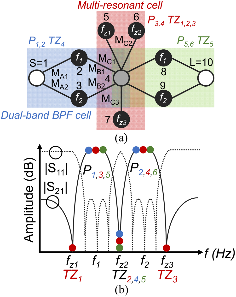
Fig. 1. Dual-band BPF concept. (a) CRD. White circles – source (S) and load (L); black circles – resonating nodes; gray circle – non-resonating node (NRN); black lines – couplings. (b) Conceptual transfer function shaped by five TZs and six poles (three per band).
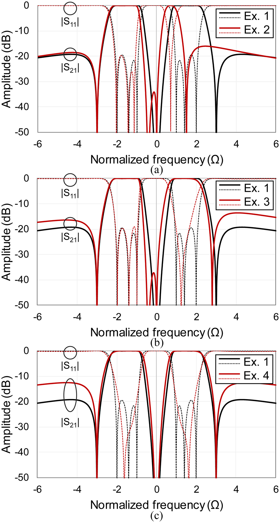
To demonstrate the theoretical and operating principles of the proposed dual-band BPF concept, various synthesized transfer functions are illustrated in Fig. 2. In particular, Fig. 2(a) shows how symmetric and asymmetric transfer functions can be realized by readily allocating the TZs around the passbands. In Fig. 2(b), transfer function reconfigurability in terms passbands with equal and unequal passbands is demonstrated. Lastly, the ability to realize flat amplitude and equi-ripple type passbands is shown in Fig. 2(c). The coupling coefficients for all the aforementioned examples are listed in Table 1.

Fig. 2. Theoretically synthesized power transmission (|S 21|) and reflection (|S 11|) responses of the CRD in Fig. 1 using the coupling coefficients in Table 1. (a) Asymmetric transfer functions by reallocating TZs. (b) Equal and unequal passband bandwidths. (c) Different types of transfer functions (flat versus equi-ripple passband).
Table 1. Coupling coefficients used in the examples in Fig. 2

While alternative practical realization schemes may be used for translating a CRD to an actual physical filter structure, this paper explores the use of LEs for both its resonators and coupling elements in an effort to minimize FOM by reducing size (i.e., A in (1)). Fig. 3 shows the power transmission and reflection response of a dual-band BPF design with passbands centered at 1 (BW: 150 MHz) and 1.5 GHz (BW: 350 MHz) for alternative types of resonators and inverters (e.g., first-order low-pass or high-pass pi-type equivalent) using synthesized and linear-circuit simulations. In particular, the following cases are considered: (i) CRD-based synthesis (black trace), (ii) parallel LC resonators and first-order high-pass pi-type inverters (red trace), (iii) parallel LC resonators and first-order low-pass pi-type inverters (blue trace), and (iv) series LC resonators (green trace). Whereas conventional BPFs are typically implemented with parallel LC resonators (e.g., in the BPFs in [Reference Simpson, Gómez-García and Psychogiou18, Reference Hong20]), this approach results in closely spaced spurious bands (as shown in the red and blue traces of Fig. 3) and BW squinting (e.g., as shown in the blue trace of Fig. 3). To reduce the out-of-band spurious resonances and increase the out-of-band spurious-free BW, integration schemes using a minimum number of inverters may be considered. This is achieved by combining the parallel-type resonators with their preceding/proceeding impedance inverters to create inverter-less series-type resonators as shown in Fig. 4. For example, each of the parallel-type resonators (e.g., resonator 5 in the CRD in Fig. 1) and its preceding inverter (e.g., M C1 in the CRD in Fig. 1) is transformed to a series type resonator (e.g., L Z1, C Z1 in Fig. 4). Similarly, the resonators that introduce poles (e.g., resonator 2 in the CRD in Fig. 1) and the inverters next to them (e.g., M A1 and M B1) are replaced with a series type resonator (e.g., L 1, C 1).

Fig. 3. Simulated power transmission (|S 21|) and reflection (|S 11|) responses of the dual-band BPF for alternative types of resonators and inverters for two passbands centered at 1 and 1.5 GHz and nominal passband bandwidths of 150 and 350 MHz. Black trace: synthesized response using the CRD in Fig. 1, red trace: linear simulated response using parallel LC resonators and LE inverters represented by their first-order pi-type high-pass circuit-equivalent, blue trace: linear simulated response using parallel LC resonators and inverters represented by their first-order low-pass pi-type circuit equivalent, and green trace: linear simulated response using series LC resonators.

Fig. 4. LE circuit-schematic of the dual-band BPF using series LC resonators.
The inverter-less circuit-schematic implementation of the CRD in Fig. 1 is shown in Fig. 4. Its component values are obtained using equations (2)-(4) when assuming M A is equivalent to MB. Z 0 is the system reference impedance, ωi and ω zi, respectively denote center frequency of each passband and of each TZ. Furthermore, Δ is the bandwidth scaling factor of the low-pass to bandpass frequency transformation. Since the passbands exhibit different fractional bandwidths (FBWs), the couplings for each passband are different (e.g., M A1 does not equal to M A2; this is shown in example 3 in Fig. 2). The power transmission and reflection response of the proposed inverter-less series-resonator-based circuit schematic is shown in Fig. 3 (green trace). As shown, its out-of-band response is superior to the rest of the parallel LC resonator implementations. In addition, this integration scheme uses a significantly smaller number of components (14 as opposed to 47 used in the rest of the LE implementations using parallel LC resonators) which results in smaller physical size.


Experimental results
In order to experimentally validate the operational principles of the proposed dual-band series LE-resonator based BPF, a prototype was designed, manufactured, and measured at L-band. In particular, the prototype was designed for passbands centered at 1.0 and 1.5 GHz with bandwidths of 146 and 105 MHz. The prototype was built on a Rogers RO4003C substrate with the following characteristics: relative permittivity εr = 3.38, thickness H = 1.52 mm and a dielectric loss tangent tanδD = 0.0021. The design was carried out using the design principles in the section “Theoretical foundations” and the software package Advanced Design System (ADS) from Keysight Technologies. The RF performance was experimentally validated with a Keysight N5224A PNA in terms of S-parameters.
The layout and a photograph of the manufactured dual-band BPF are shown in Fig. 5(a) and Fig. 5(b), respectively. The values of the LE components are first determined using (2)–(4). Afterwards, their values are optimized through full-wave simulations in ADS in order to account for the parasitics of the mounting pads of the SMD components. Due to the desired transfer function resulting in small capacitance values (e.g., 0.035 pF), the capacitors C 1, C 2, and C z3 were implemented with two series cascaded SMD components. A comparison of the RF-measured and EM-simulated power transmission and reflection response is shown in Fig. 6(a). Furthermore, Fig. 6(b), illustrates the RF measured filter response in a wider frequency range between 0 and 10 GHz in order to demonstrate the wide out-of-band isolation characteristics of the proposed dual-band BPF concept. As shown, the obtained agreement between measured and simulated responses successfully validates the series-resonator-based dual-band BPF concept using cascaded transversal and multi-resonant cells. The measured RF performance can be summarized as follows: lower passband – center frequency of 1.02 GHz, 3-dB-referred BW of 146 MHz (i.e., of 14.3% in relative terms), and minimum in-band IL of 2.0 dB, upper passband – center frequency of 1.45 GHz, 3-dB-referred BW of 105 MHz (i.e., of 7.3%), and minimum in-band IL of 2.7 dB, stopband rejection >30 dB from 0–894 MHz, 1.17–1.34 GHz, and 1.72–6.9 GHz. The prototype resulted in physical size of 15.4 × 20.6 mm, or 0.063λ × 0.085λ. Table 2 shows a comparison with current state-of-art designs. As shown, the proposed dual-band BPF exhibits smaller physical size and wider out-of-band rejection than the rest of the dual-band BPF topologies. Furthermore, it exhibits among the largest number of poles and TZs.

Fig. 5. Manufactured prototype (dimensions: 20.8 mm × 15.4 mm) of the dual-band BPF. (a) Layout. (b) Photograph. The components used are as follows: C 1 = 0.2 pF (ATC 600S 0R4 and ATC 600S 0R4), C 2 = 0.033 pF (ATC 600S0R1 and AVX 04021JR05), C z1 = 0.9 pF (ATC 600S 0R9), C z2 = 0.1 pF (ATC 600S 0R1), C z3 = 0.45 pF (ATC 600S 0R9 and ATC 600S 0R9), L 1 = 0402DC-56N (56 nH), L 2 = 0402DC-43N (43 nH), L z1 = 0908SQ-25N (25 nH), L z2 = 0805HT-10N (10 nH), and L z3 = 0908SQ-19N (19 nH).

Fig. 6. EM-simulated and RF-measured power transmission (|S 21|) and reflection (|S 11|) responses of the dual-band filter prototype in Fig. 5. (a) Frequency range: 0–3 GHz. (b) Frequency range: 0–10 GHz.
Table 2. Comparison with SOA dual-band filters.

AWLR – Acoustic Wave LE Resonator, Rej. Range – Out-of-band Rejection >30 dB.
Conclusion
A new class of dual-band BPFs has been presented. The proposed dual-band BPF concept has been developed for the 2019 Student Design Competition of EuMW and exhibits highly selective quasi-elliptic transfer functions that are shaped by six poles and five TZs. It is based on cascaded transversal and multi-resonant cells that are materialized with series resonators for size compactness and wide spurious-free out-of-band response. The proposed inverter-less dual-band BPF design approach was experimentally validated at L-band through a LE BPF prototype with two bands centered at 1.02 and 1.45 GHz.
Acknowledgement
This work was supported in part by the National Defense Science and Engineering Graduate Fellowship and the National Science Foundation, award number award number 1731956. The authors would like to thank Keysight for providing access to the software package ADS, Roger Corporation for providing the RO4003 substrate and Coilcraft for the SMD inductors.
 Andrea Ashley was born in Tulsa, OK, USA in 1992. She received the B.S. degree in Mechanical and Electrical Engineering from Kettering University, Flint, Michigan, in 2014. She is currently pursuing the Ph.D. degree in Electrical Engineering at the University of Colorado Boulder, CO, USA. Her current research interests include the design, characterization, and synthesis of reconfigurable microwave non-reciprocal RF filters and circulators. Mrs. Ashley is a member of the IEEE Microwave Theory and Techniques Society (IEEE MTT-S) and the Applied Computational Electromagnetics Society (ACES). She is the recipient of the 2018 National Defense Science and Engineering Graduate Fellowship, the 2018 EUMC Young Engineer Prize, the University of Colorado's Dean's Graduate Assistantship, and the ECEE Gold Award for Research. She received the first-place prize in the 2018 International Microwave Symposium (IMS) student filter design competition and the 2018 European Microwave Week (EuMW) student filter design competition.
 Dakotah J. Simpson was born in Thornton, CO, USA in 1994. He received the B.S. degree in Electrical Engineering from the South Dakota School of Mines and Technology, Rapid City, South Dakota, in 2017. He is currently pursuing the Ph.D. degree in Electrical Engineering at the University of Colorado Boulder, CO, USA. His current research interests include the design, characterization, and synthesis of reconfigurable microwave single-ended and balanced filters. Mr. Simpson is a member of the IEEE Microwave Theory and Techniques Society (IEEE MTT-S) and the Applied Computational Electromagnetics Society (ACES). He is the recipient of the MTT-S 2018 Graduate Fellowship, the University of Colorado's Dean's Graduate Assistantship and ECEE Gold Award for Research, and the Lockheed Martin Endowed Graduate Fellowship. He received the first-place prize in the 2018 International Microwave Symposium (IMS) student filter design competition and the 2018 European Microwave Week (EuMW) student filter design competition.
 Dimitra Psychogiou received the Dipl.-Eng. degree in Electrical and Computer Engineering from the University of Patras, Patras, Greece, in 2008, and the Ph.D. degree in Electrical Engineering from the Swiss Federal Institute of Technology, Zürich, Switzerland, in 2013. From 2013 to 2016, she was a Post-Doctoral Research Associate and a Senior Research Scientist with Purdue University, West Lafayette, IN, USA. She is currently an Assistant Professor of Electrical, Computer and Energy Engineering with the University of Colorado at Boulder, Boulder, CO, USA. Her current research interests include the RF design and characterization of reconfigurable microwave and millimeter-wave passive components, RF-MEMS, acoustic-wave-resonator based filters, tunable filter synthesis, and frequency-agile antennas.