


I. INTRODUCTION
In recent years, various approaches have been proposed to realize tunable bandpass filters that are employed to minimize size and mass of the front-ends. Similar techniques can be adopted to realize a fine-tuning of the filters to compensate for tolerances of the realization process (mainly machining and assembling) and temperature variations that may cause a drift of the filter response.
A reasonable trade-off among tuning capabilities, high unloaded Q, low cost, and small size, must be identified. For instance, magnetically tunable filters show wide tuning ranges and high Q, but are bulky and consume considerable DC power [Reference Uher and Hoefer1]. Tunable filters realized on planar technology based on RF MEMS [Reference Ocera, Farinelli, Mezzanotte, Sorrentino, Margesin and Giacomozzi2] or ferroelectric components [Reference Courreges, Li, Zhao, Choi, Hunt and Papapolymerou3] offer compact size, fast tuning speed, and wide tuning range, but limited Qs (<300). Higher Qs (500–1500) were reached using evanescent-mode cavities [Reference Park, Reines, Patel and Rebeiz4] or dielectric-loaded resonators [Reference Winter and Mansour5], in structures which use customized MEMS devices such as varactors or movable membranes.
As is well known, RF MEMS represent an attractive technology for microwave applications thanks to their low insertion loss, low-power consumption, low-cost and compact size [Reference Farinelli6]. High-Q tunable filters can be obtained by suitably combining RF MEMS and high-Q cavity resonators. In [Reference Stefanini, Chatras, Pothier, Orlianges and Blondy7], a MEMS varactor has been used in a ridge-loaded cavity at 5 GHz to tune its resonant frequency resulting in a (measured) Q above 500 and a tuning range up to 10%.
A new tuning concept for high-Q tunable bandpass filters employing Ohmic cantilever RF MEMS switches has been patented in 2010 [Reference Ligander, Persson, Pelliccia, Bastioli and Sorrentino8] and the first experimental results with real MEMS built at Fondazione Bruno Kessler (FBK) in [Reference Pelliccia, Cacciamani, Farinelli, Ligander, Persson and Sorrentino9] showed Qs about 1000.
Another MEMS-based tuning approach for waveguide filters was proposed by the same authors in [Reference Pelliccia, Farinelli and Sorrentino10] showing similar performances.
A new concept of the adjustable bandpass filter is proposed in this paper. The filter is based on rectangular waveguide resonators loaded with thin E-plane metal strips on a low-loss substrate. Ohmic RF MEMS switches can be used to modify the lengths of the different metal strips so as to digitally change the resonant frequency of the fundamental TE101 mode. In [Reference Pelliccia, Nocella, Cacciamani, Gentili, Farinelli and Sorrentino11], this concept was employed to move the center frequency of a filter to realize a reconfigurable response. In the present paper, we show that the same tuning device can be opportunely modified to achieve a frequency tuning as small as 0.1%, enabling in this way a fine tuning, which can be used to compensate for mechanical tolerances and/or temperature drifts.
This approach has the advantage of allowing a high number of small frequency steps along with high-Qs in all states. Moreover, the design and fabrication are easy enough to allow for potentially low-cost manufacturing.
To illustrate and validate the proposed tuning principle, a resonant cavity at X-band has been designed and simulated, and then the concept was applied to a third-order prototype realized with hardwired connections instead of MEMS. The results obtained are very satisfactory and demonstrate the feasibility and effectiveness of the approach proposed.
II. TUNING PRINCIPLE
Two kinds of E-plane resonators fabricated on a low-loss and low-permittivity substrate are depicted in Fig. 1.

Fig. 1. (a) Conventional E-plane resonator and (b) strip-loaded E-plane resonator.
The resonator of Fig. 1(a) consists of a waveguide length loaded with a low-loss and low-permittivity substrate comprised between two E-plane septa printed on the same substrate. The distance d between the septa determines the input (output) coupling between the dominant TE10 mode of the waveguide and the TE101 resonant mode of the resonator (i.e. an inductive coupling), while the distance l between the septa determines the resonant frequency of the resonant TE101 mode [Reference Shih12].
In Fig. 1(b), additional E-plane conductive thin strips are placed between the septa. They can be used to change the resonant frequency of the TE101 mode, in a similar way as in [Reference Pelliccia, Farinelli and Sorrentino10]. We termed the structure in Fig. 1(b) a strip-loaded E-plane resonator. The thin strips act like metallic tuning screws located in the region of the E-field maximum of the resonant mode: the longer the strips the lower the resonant frequency [Reference Matthaei, Young and Jones13].
The strip-loaded E-plane resonator of Fig. 1(b) is indeed amenable to tuning as illustrated in Fig. 2. Here, MEMS switches are placed along the thin strips very close to the short-circuited ends (i.e. close to the top waveguide broad wall).
Fig. 2. Tunable strip-loaded E-plane resonator using MEMS switches.
In the practical implementation, the MEMS switches will be realized as ohmic cantilever switches fabricated according to FBK technology. They consist of 110-μm wide and 170-μm long gold thin beams suspended above an interrupted line and a DC actuation pad underneath the beam. In the on-state (with roughly 50 V DC voltage) the switch is closed and can be modeled as a very low series resistance (R on ~ 1 Ω), whereas in the off-state the switch is open and its effect can be modeled as a low series capacitance (C off ~ 10 fF). Such approximations are valid up to 25 GHz [Reference Farinelli6].
To illustrate the tuning principle, let us consider the electric field distribution in the longitudinal section of the waveguide (Fig. 3). When all five switches are in the on-state (state 11111) the strips behave as continuous conducting lines, the electric field is confined underneath them, and the resonant frequency is lowered (Fig. 3(a)). When instead all the switches are in the off-state (state 00000), the E-field goes through the interrupted lines (Fig. 3(b)), and the resonant frequency is increased with respect to the previous case. As a result, the resonant frequency of the mode in the cavity is lowered by switching on the MEMS.
Fig. 3. E-field behavior when the MEMS is on (a), E-field behavior when the MEMS is off (b) of the fundamental resonant mode of the resonator in Fig. 2.
The entity of the frequency shift can be controlled by choosing the number and the lengths of the strips as well as their positions inside the cavity. Intermediate frequency steps can be enabled by switching only some strips. As will be shown in the next section (Tables 1 and 2), frequency shifts between 9 and 64 MHz can be obtained.
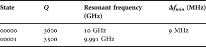
Table 1. Comparison between the state (00000) and (00001) for X-band cavity corresponding to the minimum frequency shift Δf min.
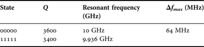
Table 2. Comparison between the states (00000) and (11111) for X-band cavity corresponding to the maximum frequency shift Δf max.
III. SINGLE TUNABLE RESONATOR
A MEMS-based tunable strip-loaded E-plane resonator at X-band is illustrated in this section.
Referring to Fig. 4, the E-plane circuit pattern (i.e. septa and strips) and the MEMS switches are designed on a 500-μm thick quartz substrate using gold. The strips that enable the tuning are 500-μm wide. Quartz is preferred over silicon because of its lower permittivity (3.78) and tanδ (10−4).
Fig. 4. HFSS models for a feasible MEMS-base tunable strip-loaded E-plane resonator: the MEMS and the strips are on the metal septa substrate.
Figure 4 shows the fabrication details of the tuning septum. The quartz substrate protrudes in the waveguide broad wall to allow the connection of the MEMS bias lines to the external DC circuitry. The 10-μm wide bias lines are realized with high resistivity polysilicon [Reference Farinelli6] and are placed underneath the substrate metallization (see Fig. 4). The slots opened in the waveguide broad wall are thin enough in order not to interrupt the flowing current (that is zero in the middle of the transverse plane for the TE101 mode of a waveguide), so as to prevent undesired radiation.
Two ohmic cantilever MEMS switches have been inserted in parallel in each strip (thus ten switches in each resonator). The equivalent series resistance is roughly 0.5 Ω in each strip.
The structure has been carefully modeled using high frequency structural simulator (HFSS) including the bias lines, the lossy substrates and the actual material conductivity. The simulation results of the tunable cavities in X-band are summarized in Tables 1 and 2.
Each cavity presents five MEMS switches that can have two different states. While the number of combinations is 32, some of those are equivalent to each other, so that the number of different states reduces to 20. Simulations were carried out considering the internal walls covered by silver plating.
Table 1 shows that the minimum frequency shift of 9 MHz is obtained by switching only one MEMS, i.e. between state (00000) and (00001). As can be seen, a slight decrease of the Q factor is produced. The maximum frequency shift (Table 2) is realized when switching all five MEMS, i.e. between state (00000) and (11111). A 64 MHz shift is obtained, with a somewhat higher Q degradation. Nonetheless the estimated quality factors are still very satisfactory.
IV. DESIGN OF A THIRD-ORDER PROTOTYPE AND MEASUREMENTS
To prove the concept described, a third-order tunable filter was designed. Design specifications are: center frequency f 0 = 10.05 GHz, return loss better than 20 dB and a FBW of 2.6%. The design of the filter, whose model is sketched in Fig. 5(a), was carried out considering the switches in the configuration 10011 for each of the three cavities, as pointed out in Fig. 5(b). The configuration (10011) corresponds to an intermediate frequency state, from which one can move to higher or lower frequencies by changing the switch states according to the compensation needed to perform.
Fig. 5. (a) Three-dimensional model of the third-order waveguide filter designed in HFSS with E-plane circuit proposed for the fine tuning and (b) simulated response with configuration 10011 of the switches in each cavity.
The ohmic MEMS switches have been replaced by hardwired connections emulating the two MEMS states: a 100-μm thick continuous copper line is used to emulate the on-state MEMS, whereas a 200-μm gap in the lines is used to emulate the off-state MEMS. The hardwired circuits realized are alternatively assembled in the waveguide (Fig. 6). The substrate is Arlon DiClad 880, which has tanδ = 10−3 and relative permittivity ε r = 2.17.
Fig. 6. Waveguide cut on E-plane where different hardwired printed circuits are alternatively mounted enabling fine tuning of a third-order filter.
The measurement of the third-order prototype with configuration 10011 of the switches in all the three cavities presents a deviation from the simulated response as shown in Fig. 7(a). This is a typical example of a filter response affected by fabrication tolerances. In this specific prototype, this effect can be due to tolerances in the metal cavity or in the E-plane circuit. In general, the effects of mechanical errors are more significant for narrow band or high center frequency filters. In the latter case, it would be tricky to operate a fine tuning with external screws due to the smaller size of the hardware. It is in such cases that the proposed tuning device finds its best usefulness.
Fig. 7. (a) Measured response of the filter having a configuration of the switches 10011 in each cavity and (b) re-established response obtained by a different configuration of the switches (00001) in the second cavity.
The undesired effect that causes the mismatch of the filter responses can be compensated for applying a proper configuration of the switches in some of the cavities. In the present case, the correct response is restored using the state 00001 in the second cavity. In the hardwired realization, this state change is obtained by replacing the E-plane circuit. The restored response of the filter is shown in Fig. 7(b), where the return loss is <−20 dB as in the simulations.
The measured Q can be derived from the minimum insertion loss of the measured response (ΔS 21 = 0.41 dB) from the formula [Reference Sorrentino and Bianchi14]
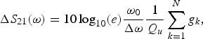 $$\Delta {S_{21}}\lpar \omega \rpar =10\, {\log _{10}}\lpar e\rpar \displaystyle{{{\omega _0}} \over {\Delta \omega }}\displaystyle{1 \over {{Q_u}}}\mathop \sum \limits_{k=1}^N {g_k}\comma \;$$
where ω 0 is the center angular frequency of the filter, Q u is the unloaded Q of the resonators and the terms g k are the g-parameters of the canonical Chebyshev filter response (g 1 = 0.6291, g 2 = 0.9702, and g 3 = 0.6291). By inverting the previous formula, it is found that
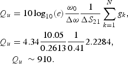 $$\eqalign{{Q_u}& =10\, {\log_{10}}\lpar e\rpar \displaystyle{{{\omega _0}} \over {\Delta \omega }}\displaystyle{1 \over {\Delta {S_{21}}}}\mathop \sum \limits_{k=1}^N {g_k}\comma \; \cr {Q_u}& =4.34\displaystyle{{10.05} \over {0.2613}}\displaystyle{1 \over {0.41}}2.2284\comma \; \cr & {Q_u}\; \sim 910.}$$
Such value of Q is lower than that reported in Tables 1 and 2 because we have used a high-loss substrate (tanδ = 10−3) to build the prototypes.
Using lower losses substrates such as quartz (tanδ = 10−4) the loss performances can be improved substantially. The integration of real MEMS is currently being developed as an extension of this project. We expect no significant changes of the performance with respect to the fixed-connection prototype because of the very low series resistance of the MEMS when they are on and their low capacitance in the off state, as already shown in [Reference Ocera, Farinelli, Mezzanotte, Sorrentino, Margesin and Giacomozzi2].
V. CONCLUSIONS
A new concept has been proposed for high-Q MEMS-based adjustable bandpass filters with small frequency steps. A waveguide resonator has been used consisting of a rectangular waveguide section comprised between two metallic E-plane septa and loaded with thin E-plane conductive strips on a low-loss substrate. The thin strips can be connected to the top waveguide wall by RF switches. In this manner, the TE101 mode resonant frequency can be modified depending on the switch state.
This tuning principle allows for a fine tuning, which is very useful at high frequencies where resonator size is particularly small and where compensation for manufacturing tolerances and temperature variations are necessary. High Q is maintained over the whole tuning range enabling the realization of low-loss filters.
The proposed approach was applied to the design of a third-order filter with hardwired connections instead of RF MEMS switches. The measurements of the realized prototype showed that by changing the configuration of the switched inside the cavities, the response of the filter can be finely tuned. The measured Q factor was roughly 1000 (in the measured prototype reported the Q was 910), which is lower than the single cavity simulated (based on quarz) because a higher losses substrate was used with the only intent of proving the concept.
The advantage of this approach over classical tuning screws is that small frequency steps are achievable in a controlled and repeatable way. Fine-tuning can be enabled even in cases where, for dimensional issues, it would be impracticable with screws. Moreover, given the possibility to control the switches electronically, this approach lends itself to a remote tuning control.
Future works include the design of an adjustable E-plane filter with real ohmic cantilever MEMS switches fabricated at FBK foundry (Fondazione Bruno Kessler, Trento) [Reference Farinelli6].
Fabrizio Gentili was born in Foligno, Italy, in 1984. He received his Master Laurea degree (with distinction) in Electronic Engineering from the University of Perugia (Italy) in February 2010. In 2009, he carried out his master's thesis at the University of Bristol (UK) where he was involved in the design of photonic nanoantennas. In March 2010, he joined RF Microtech where his work regarded the design of antennas and beam-forming networks for array antennas. In December 2010, he started his Ph.D. activity at the University of Perugia under the advisement of Professor Roberto Sorrentino. In February 2014, he successfully defended his dissertation concerning innovative solutions for RF and microwave filters. Since April 2014, he has been a post-doctoral researcher at the Institute of Microwave and Photonic Engineering of Graz University of Technology (Austria).
 Valeria Nocella received her Laurea degree from Università di Perugia in Electronic Engineering in May 2012. In 2011–2012, she carried out her thesis research with Ericsson AB, Mölndal, Sweden, where she was involved in the design of innovative transitions at high frequencies. In May 2013, she joined the Department of Electronic and Information Engineering (DIEI) of the University of Perugia (Italy) under the advice of Professor Roberto Sorrentino. She is currently working as RF and microwave engineer and her research activities include: the design of innovative and compact microwave waveguide filters and diplexers, tunable and reconfigurable bandpass filters and RF sensors. In December 2013, she passed the Ph.D. examination and officially become a Ph.D. student at the University of Perugia.
Luca Pelliccia was born in Foligno, Italy, in 1984. He received his Master's Laurea degree (with distinction) in Electronic Engineering from the University of Perugia, Italy, in April 2009. In 2008–2009, he carried out his master's thesis research in Ericsson AB, Mölndal (Sweden), where he was involved in the design of innovative concepts of waveguide filters for microwave applications at E-band frequencies (71–86 GHz). In May 2009, he joined the Department of Electronic and Information Engineering of the University of Perugia. His research activities include the development and design of new solutions for high-Q tunable filters, micromachined filters, and miniaturized waveguide filters and diplexers. His research involvement has resulted in the publication of several papers in the Proceedings of International Microwave Conferences. In November 2012, he received his Ph.D. degree under the advice of Professor Roberto Sorrentino. He is currently working at RF Microtech (Perugia) as a microwave engineer.
Fabrizio Cacciamani was born in San Benedetto del Tronto, Italy, in 1981. He received his Master's Laurea degree in Electronic Engineering from the University of Perugia, Italy, in 2009. In February 2010, he joined the Department of Electronic and Information Engineering (DIEI) of the University of Perugia (Italy) under the advice of Prof. Roberto Sorrentino. His research activities include: development and design of reflectarray antennas radiating element, and microwave filters. For the last 3 years he has collaborated with RF Microtech (spin-off of Perugia University, Italy) in several international research projects concerning RF MEMS, microwave bandpass filter and antenna design.
Paola Farinelli was born in Assisi, Italy, on September 19, 1978. She received her Laurea degree (with distinction) and the doctoral degree in Electronic Engineering from the the University of Perugia, Italy, in 2002 and 2006, respectively. Her research activity focuses on the electromagnetic modeling and design of reconfigurable RF MEMS components, and circuits. She has been involved in different European projects as (ESA projects, Network of excellence, FP7 projects), which enabled close collaborations with many industrial and academic research institutes. She is currently leading the RF MEMS Research and Development Unit at RF Microtech, a spin-off company of the University of Perugia.
Roberto Sorrentino is a Professor at the University of Perugia, Italy. His research activity deals with the analysis and design of microwave and millimeter-wave circuits and antennas. He is the author or co-author of more than 150 technical papers in international journals, 300 refereed conference papers, and three books. Roberto Sorrentino is an IEEE Fellow (1990), recipient of the MTT-S Meritorious Service Award (1994), the IEEE Third Millennium Medal (2000), Distinguished Educator Award from IEEE MTT-S (2004). He was the Editor-in-Chief of the IEEE Microwave and Guided Wave Letters (1995–1998) and was among the founders and the President of the European Microwave Association (1998–2009).


