1. INTRODUCTION
Gigawatt power electron beams produced by high-voltage pulse generators have been used in diverse applications as high-power microwave generation (Gold et al., Reference Gold and Nusinovich1997; Liu et al., Reference Liu, Li, Zhang, Wen, Wan and Zhang2007), free electron lasers (Freund et al., Reference Freund and Antonsen1996), flash X-ray generation (Maenchen et al., Reference Maenchen, Cooperstein, O'Malley and Smith2004), and surface modification (Schneider et al., Reference Schneider, Reed, Kaye, Duggan and Morgan1997). In these various devices, the presence of prepulse in the pulse power systems (Miller, Reference Miller1982; Smith, Reference Smith2004) poses some problems in the beam generation process. The large mismatch in the capacitance of Marx and Blumlein leads to high prepulse and damages the important insulating components of the system (Mondal et al., Reference Mondal, Kumar, Roy, Mitra, Sharma, Singh, Rao, Mittal, Nagesh and Chakravarthy2007a; Kumar et al., Reference Kumar, Mitra, Senthil, Sharma, Nagesh, Singh, Mondal, Roy and Chakravarthy2007b; Roy et al., Reference Roy, Mondal, Menon, Mitra, Kumar, Sharma, Mittal and Chakravarthy2007; Reference Roy, Menon, Mitra, Kumar, Kumar, Sharma, Mittal, Nagesh and Chakravarthy2008a; Reference Roy, Menon, Mitra, Kumar, Kumar, Sharma, Patel, Sharma, Mittal, Nagesh and Chakravarthy2008b). In the KALI system, prepulse voltage was a signature of unmatched energy storage capacity of MARX generator and Blumlein pulse forming line. Apparently, excess storage of energy in the MARX generator, while charging Blumlein, is an acceptable practice. It ensures little increment in charging of Blumlein voltage and also takes care of losses which are difficult to estimate, i.e., high frequency copper loss, corona loss, and losses in the spark gaps. Common practice of storing extra energy in the MARX generator ensures sufficient output pulse voltage and current. But when the amount of stored excess energy becomes sufficiently high, it can be a potential threat to the health of the system. In a high-voltage system, damage of solid dielectric is the most unacceptable damage that can be observed. All of the design calculations remain mostly concentrated on saving the solid dielectric from any kind of failure. Lots of studies and experiments were conducted to ensure the field withstanding capacity of any solid dielectric and its surface. Two main parameters are found to be responsible for dielectric failure, i.e., applied electric field and its duration. Now, in case of a severely unmatched system of pulsed power, the probability of failure of dielectric increases by many folds due to unexpectedly high duration of application of high-voltage at certain points. Once the system is activated, unused excess stored energy oscillates within the system. The problem becomes more dominant in case of applications like relativistic electron beams (REB) diode. REB diodes by its natural behavior get shorted after about 100–200 ns (after application of high-voltage pulse) depending on the anode and cathode plasma velocity (Roy et al., Reference Roy, Mondal, Menon, Mitra, Kumar, Sharma, Mittal and Chakravarthy2007; Reference Roy, Menon, Mitra, Kumar, Kumar, Sharma, Mittal, Nagesh and Chakravarthy2008a; Reference Roy, Menon, Mitra, Kumar, Kumar, Sharma, Patel, Sharma, Mittal, Nagesh and Chakravarthy2008b; Mazarakis et al., Reference Mazarakis, Poukey, Maenchen, Rovang, Menge, Lash, Smith, Johnson, Halbleib, Cordova, Mikkelson, Gustwiller, Stygar, Welch, Smith and Corcoran1997). As a results of which, at the end of the pulse, excess energy stored in the MARX generator gets a short-circuit path through the diode. In a short-circuited path, this excess energy oscillates rigorously and dampens very slowly as the loop resistance is significantly low. Such resonating oscillations can sustain for very long time, of the order of several milliseconds, depending on the specific system structure and design. This generates substantially high oscillating voltage at locations inside the Blumlein and MARX. High field stress for such millisecond duration observed by solid dielectrics during this period can be much higher than expected during design of the system and can potentially damage the system after a few shots are taken. In this paper, such observation analysis and suitable modifications are elaborated in connection with the KALI system. Damaged components and pattern of damage is shown and post modification results are also tabulated in following sections.
2. HIGH-VOLTAGE FAILURE ASPECTS IN KALI
The KALI pulse power system consists of a Marx generator (1.5 MV, 25 kJ), a Blumlein pulse forming transmission line (1 MV, 5 kJ), a gas (SF6) spark gap to generate the high-voltage pulse, and a gas prepulse switch to minimize the prepulse voltage on the electron beam diode. An explosive emission diode was used to generate intense relativistic electron beams (IREBs). A vacuum explosive electron emission diode was used to generate IREBs. The high-voltage pulse generated from the pulse power system is applied to the electron beam diode. During operation of KALI system it has been repeatedly noticed that insulation support of Blumlein transmission line failed after few shots are taken. Moreover it has been noticed that particularly one insulation support located very close to MARX generator and separating outermost and intermediate cylinder of Blumlein transmission line, was the most prone to failure. Damaged insulator is shown in Figure 1 which shows the severity of high-voltage breakdown. Surface field stress at the point of failure is 50 kV/cm at rated output voltage which is reasonably within the acceptable limit of Perspex in oil for pulsed voltage of 1 µs duration.

Fig. 1. Damaged insulator support inside Blumlein transmission line.
3. SIMULATIONS AND ANALYSIS
Simulation of the equivalent circuit is used as a tool to find out the reason of such a repeated failure of the system. Equivalent MARX capacitance of 23 nF and Blumlein capacitance of 10 nF is used for the simulation. Charging inductor of 13 µH and Blumlein inductor of 8 µH was used in this practical system. Simulated results bring out the fact that due to large capacitance mismatch of MARX and Blumlein sufficiently high amount of energy remain left out in the MARX generator during firing of Blumlein spark-gap and diode pulse operation. REB diodes, by virtue of nature, get shorted through self-generated plasma within 100–200 ns of commencement of beam generation. Once the load gets shorted this extra energy of the MARX generator oscillates to decay for a very long time and certain points inside Blumlein exhibits highly oscillating transient voltage for longer period of time than accounted for perfectly mismatched load after the output pulse. Simulation shows that amplitude of these pulses can be as high as 80% of the erected MARX voltage, i.e., 1 MV and can continue for even several milliseconds depending on the dynamic load pattern of the REB diode.
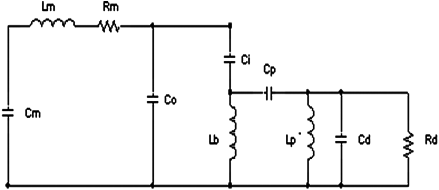
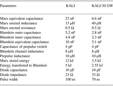
The equivalent circuit of the Blumlein during charging is shown in Figure 2. Here CM, LM, RM, CO, Ci, CP, Lb,Lp, Cd, and Rd are the Marx equivalent capacitance, Marx erected inductance, Marx equivalent resistance, Blumlein outer capacitance, Blumlein inner capacitance, capacitance of the prepulse switch, Blumlein channel inductance, prepulse switch inductance, diode capacitance, and diode resistance, respectively. The values of different parameters are shown in Table 1. Figure 3 shows the simulated results with older parameters mentioned above. Oscillation of residual MARX voltage is clearly visible in the simulation. In practice, it is difficult to measure the voltage at that location. Analytically, it can be proved that the residual energy at MARX generator during firing of Blumlein is (CM − CB)2/(CM + CB)2, where CM and CB are the equivalent capacitance of MARX and Blumlein, VM and EM are Marx output voltage and energy, respectively. Equivalent circuit shown in Figure 2 if solved using laplace transformation shows that voltage at Blumlein is
 $$V_B \lpar t\rpar = \displaystyle{{V_M } \over {\left({1 + \displaystyle{{C_B } \over {C_M }}} \right)}} [1 - \cos\lpar {\rm \omega} t\rpar].$$
Fig. 2. Blumlein equivalent circuit during changing.

Fig. 3. Charging and discharging of Blumlein and oscillation of residual MARX voltage with 23 nF MARX capacitance and 10 nF Blumlein capacitance
Table 1. Comparison between parameters of KALI and KALI-30 GW system

Therefore, the peak voltage at Blumlein is given by the following equation
 $$V_{Bmax } = \displaystyle{{2V_M } \over {\left({1 + \displaystyle{{C_B } \over {C_M }}} \right)}}.$$
Hence, the maximum possible energy transfer to Blumlein from MARX is
Therefore, residual energy in the MARX generator is
 $$E_R = E_M - E_B = \left({\displaystyle{{C_M - C_B } \over {C_M + C_B }}} \right)^2 E_M .$$
Hence, approximately 15%–20% of the excess energy will remain stored in the MARX generator during operation of the system, and supposedly circulate for a very long period of time after the main pulse is over. In high energy systems like KALI, this amount is pretty high and has sufficient potential to damage the system. Even more stored energy can remain stored inside the MARX generator if prefiring of Blumlein sparkgap occurs. In that case, 30%–40% of excess MARX energy (in our system, it is approximately 7 kJ–10 kJ) can oscillate inside the system and cause severe damage.
Reduction of this residual energy can be properly done by matching the MARX and Blumlein capacitances properly. Eq. (4) shows that if CM and CB are equal, then the residual energy reduces to zero. This can be achieved by adjusting MARX capacitances to that of Blumlein capacitances. A little extra energy can be kept in the MARX generator to take care of the losses during discharge. Figure 4 shows the waveform of a better matched MARX and Blumlein. It is evident from the simulated results that oscillating residual energy in the MARX is much lower and hence the oscillating long high-voltage stress is also less. Implementation of the same has been carried out in KALI system. Experimental observations are narrated below in the next section.

Fig. 4. Charging and discharging of Blumlein and Oscillation of residual MARX voltage with 6.66 nF MARX capacitance and 5 nF Blumlein capacitance.
4. MODIFICATION AND RESULTS
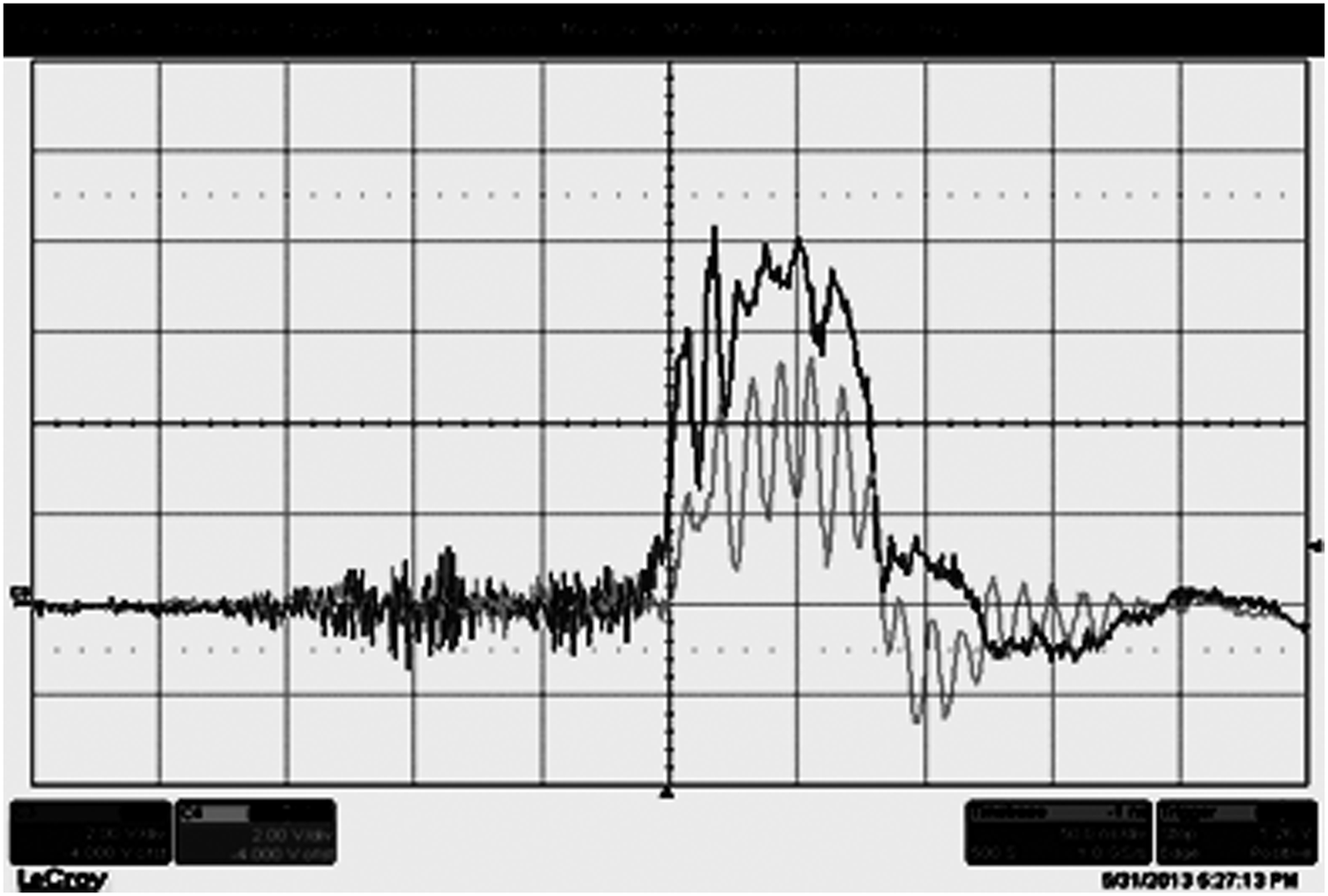
In line with the results of the simulations, Blumlein and MARX design has been modified. Blumlein capacitance is reduced to 5 nF (inner capacitance 2.3n F and outer capacitance 2.8 nF). MARX generator initially consisted of 30 numbers of 0.7 µF energy storage capacitor. These are replaced by 0.2 µF capacitors. To maintain the Blumlein charging time close to 1 µs extra 40 µH inductor is added in between MARX and Blumlein. Charging time of Blumlein is designed to be about 1.2 µs. Discharging pulse of Blumlein is estimated to generate a 70 ns (full width half maxima (FWHM)) 1 MV pulse across a 30 Ω matched load. Experiments are done to verify the same. Results obtained during experimentation are shown in Figures 5 and 6.

Fig. 5. Typical Blumlein charging waveform (700 KV, 1.2 µs).

Fig. 6. Typical REB voltage and current (700 kV, 20 kA, 70 ns).
Modifications executed in KALI-30 GW system have enhanced the reliability and ruggedness of the system as a whole. Initially, MARX generator of KALI system use to store 26 kJ (while charged to 50 kV) and approximately 12 kJ (while charged to 3 4 kV to get 1 MV erected voltage). Its erected capacitance was 23 nF and while charged to Blumlein of capacitance 10 nF to 1 MV, energy transferred to Blumlein is only 5 kJ, hence rest all energy remains unused, oscillates inside the system and damages weaker insulating components over the period of time. With present modification, stored energy inside MARX generator is 7.5 kJ (while charged to 5 0 kV) and 3.5 kJ (while charged to 34 kV to get 1 MV erected voltage). Erected capacitance of MARX is 6.66 nF and it charges Blumlein of 5.1 nF to 1 MV transferring 2.55 kJ of energy. Hence residual energy, which oscillates inside the system is significantly low and dies down fast without any damage to the insulating components of the system. Charging inductor of the Blumlein is increased from 13 uH to 40 uH to ensure uniform charging of both the Blumlein capacitors (shown in Fig. 4) unlike the previous condition of non-uniform charging (shown in Fig. 3). This reduces prepulse amplitude, ensures unwanted enhancement of localized field stress inside Blumlein transmission line and probability of insulation damage.
Effect of these modifications in the output parameters of the system is mainly in two ways, i.e., matched impedance and pulse width. These two are the parameters affected by the relative permittivity of the Blumlein medium. Previously, Blumlein transmission line was filled with castor oil (εr = 4.5), which is replaced by transformer oil (εr = 2.1) as a result of which matched impedance of the system has modified to 33 Ω from 23 Ω earlier. Previously, pulse width (FWHM) of the system was 100 ns, which has reduced to 70 ns. Table 1 shows a comparison between the parameters of KALI and KALI-30 GW system. Overall the system has become more rugged, reliable, and easily maintainable.
5. CONCLUSIONS
In high-voltage studies field stress hot spots and their duration of applications has remained crucial historically. Specifically in design of high-voltage pulsed power systems, dynamic behavior of the dielectric insulators under stress plays a crucial role. While handling high amount of stored energy dynamically, energy balance of the system becomes extremely vital. Excess of stored energy is found to play an extremely significant role in causing fatal damages in KALI system. Dynamics of stored energy during and after the main pulse has been analyzed in this paper. Simulations are used to estimate application of high-voltage at hot spots even after the pulse is over. Modifications are conducted to ensure better energy matching to reduce localized field stress. Modified system delivers reliably and output of the system shown above supports the hypothesis of energy balance.


