Introduction
Body-centric wireless communications (BCWCs) provide the wireless connectivity between the low-power devices for monitoring vital data of a human and its environment through wearable and implantable antennas. BCWCs can be applied to many fields. Some of them include medical and military applications, sport, and wireless access [Reference Hall and Hao1]. Figure 1 illustrates the concept of a BCWC system for medical telemetry applications. In such communication system, the devices can be located in a vicinity or on or inside the body [2]. Hence, the BCWCs within personal- and body-area networks can be classified as off-body, on-body, or in-body [Reference Moradi, Koski, Björninen, Sydänheimo, Rabaey, Carmena, Rahmat-Samii and Ukkonen3] (Fig. 1). Moreover, most of the devices for on-body communications are designed for operation in the unregulated frequency bands for Industrial, Scientific and Medical (ISM 2.40–2.48 GHz and/or 5.75–5.82 GHz [Reference Mazar4]) applications. The devices, for off-body communications are designed for operation in ISM bands but also can serve as an intermediary gateway node [2] allowing an interconnection with a local/remote monitoring centre via a conventional communication infrastructure such as LTE (long-term evolution) and WLAN (wireless local area network) etc. (Fig. 1). Consequently, dual-band or multifrequency operations are the main requirements of this type of communications [Reference Ojaroudi and Ghadimi5]. Hence, a wearable antenna includes dual-band operation is highly desirable.
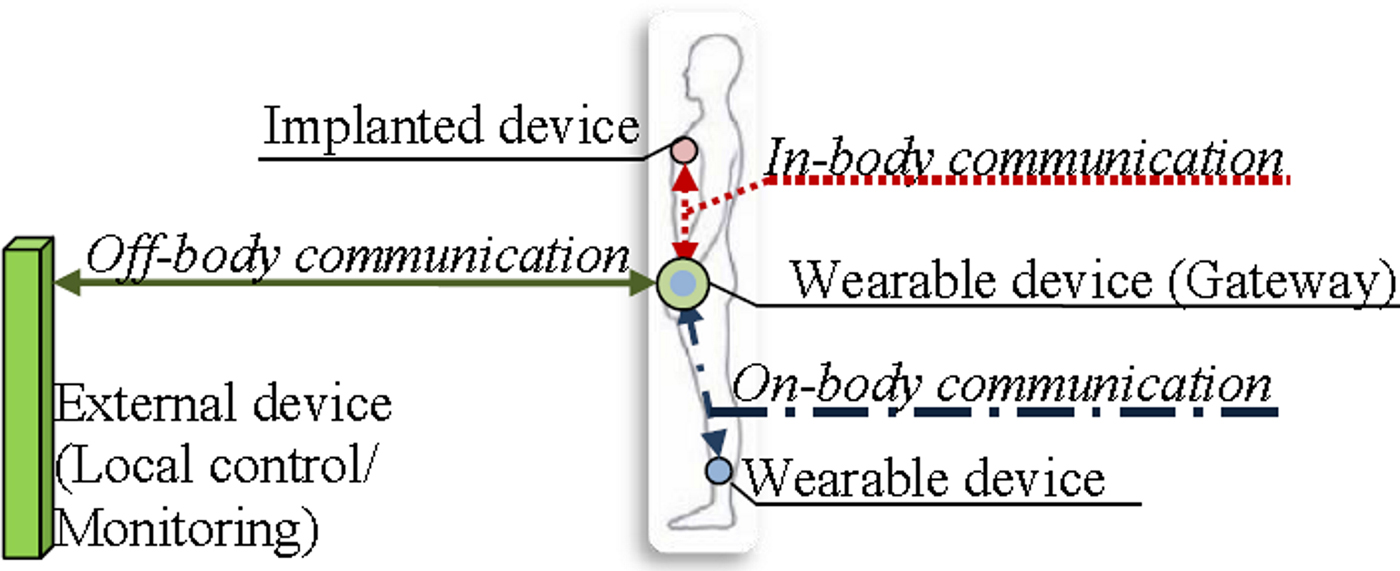
Fig. 1. An example of positions of nodes in body-centric wireless communications.
Moreover, the specific environment in which wearable antennas operate imposes explicit requirements and constraints that must be included in the antenna's design criteria [Reference Nepa and Rogier6]. For example, the main mechanical requirements are (a) lightweight, (b) low profile, (c) compactness, and (d) flexibility [Reference Hall and Hao1, Reference Chen, Liu, Nakano, Qing and Zwick7–Reference Ferreira, Pires, Rodrigues and Caldeirinha10]. In addition, wearable antennas for off- and on-body communications should show high immunity to the human body interaction, which otherwise may drastically detune the antenna input impedance and degrade the radiation efficiency [Reference Chen, Liu, Nakano, Qing and Zwick7].
During the last years, there are various antenna designs, which enable antennas with a low profile and lightweight [Reference Ojaroudi and Ghadimi11]. These antennas include the printed monopole antenna [Reference Ojaroudi, Ghadimi and Ojaroudi12–Reference Ojaroudi, Ojaroudi and Ghadimi14], printed dipole antenna [Reference Giman, Soh, Jamlos, Lago, Abdullah Al-Hadi, Abdulmalek and Abdulaziz15], printed loop antenna [Reference Belrhiti, Riouch, Tribak, Terhzaz and Sanchez16], printed F-antenna [Reference Conway, Cotton and Scanlon8], patch antenna [Reference Silva, Freire, Serres, Silva and Silva9, Reference Ferreira, Pires, Rodrigues and Caldeirinha10], coplanar waveguide – fed slot antenna [Reference Ojaroudi and Ghadimi17], fork-shaped planar antenna [Reference Kunwar and Gautam18]. Meanwhile, metasurfaces such as artificial magnetic conductor (AMC), high impedance surface (HIS), and electromagnetic bandgap (EBG) structures are widely used in wearable antenna design due to their ability to shield the radiating element from the human body and achieve good body-antenna isolation, and due to their compatibility with low profile antennas [Reference Giman, Soh, Jamlos, Lago, Abdullah Al-Hadi, Abdulmalek and Abdulaziz15]. However, the size of almost all of the wearable antennas with AMC, HIS or EBG is relatively large. In addition, it should be mentioned that many of designs for wearable antennas are proposed for operation at 2.45 GHz [Reference Conway, Cotton and Scanlon8, Reference Ferreira, Pires, Rodrigues and Caldeirinha10, Reference Sundarsingh, Kanagasabai and Ramalingam19–Reference Akhoondzadeh-Asl, Nechayev, Hall and Constantinou22] and only a few studies are conducted and reported in the open literature on design and performance of broadband and dual-band wearable antennas [Reference Silva, Freire, Serres, Silva and Silva9, Reference Giman, Soh, Jamlos, Lago, Abdullah Al-Hadi, Abdulmalek and Abdulaziz15, Reference Su and Hsieh23].
In this paper, a novel dual-band wearable compact flexible antenna is proposed for BCWCs as well as for WLAN and LTE applications. The proposed antenna consists of a modified planar dipole, meandered lines, parasitic elements, and a rectangular reflector embedded into a textile-polymer composite multilayer sandwich substrate in order to get both good antenna performance and mechanical properties. The antenna shows a planar structure, with overall dimensions of 50 mm × 40 mm × 4.6 mm and an antenna prototype mass of 11 g, which makes it suitable for practical applications in BCWCs.
The design and fabrication of the proposed antenna are explained in the section “Antenna design and fabrication”. In the section “Simulation and experimental results”, we present simulation and experimental results for dual-band operation, reflection coefficient magnitude, bandwidth, radiation efficiency, peak gain, and radiation properties of the proposed antenna in free space (FS) and on human body phantom conditions. The specific absorption rate (SAR) results of the proposed antenna placed on homogeneous human body phantom are analyzed in the section “SAR analysis”. Finally, conclusions are given in the section “Conclusion”.
Antenna design and fabrication
Antenna structure and design
Figure 2 shows the proposed antenna geometry and its detailed structure along with optimized dimensions. The antenna consists of a multilayer (Layers 1–3) rubber- and rubber-fabric substrate, a feeding strip line, a modified planar dipole antenna, four parasitic elements, two meandered lines to generate dual resonance modes, and a rectangular reflector. One of the dipole arms, one element of the feeding strip line, two parasitic elements, and one of the meandered lines are placed on the top side of the Layer 1 (Fig. 2(c)). The other dipole arm, feeding strip line element, parasitic elements, and meandered line are placed on the top side of the Layer 2 (Fig. 2(d)). Considering that the wearable antennas operate in close proximity to the human body, a metal rectangular reflector (width 40 mm and length 50 mm) is added between Layers 2 and 3, to reduce SAR in the human tissues and the effects of detuning when the antenna is placed in a vicinity of the human body. The dipole arms are shortened from the original case and then modified by adding two metal plates at both ends of the dipole to develop a compact low-profile antenna. A strip line comprises two rectangular subsections is utilized to feed the radiating elements of the antenna. The length and width of the subsections are numerically finalized to improve impedance matching in a wide frequency range. The parasitic elements are used to increase the radiation efficiency in the low-frequency band. The main requirement of the antenna is the ability to operate in ISM band of 2.40–2.48 GHz, LTE (Band 7) of 2.50–2.69 GHz, and WLAN of 5.150–5.725 GHz (Unlicensed National Information Infrastructure (U-NII): U-NII-1: 5.150–5.250 GHz; U-NII-2: 5.250–5.350 GHz and U-NII-2 Extended: 5.470–5.725 GHz). Due to the proximity of the two bands (ISM and LTE), the planar dipole and the meandered lines are designed to form a wide band that will cover the two standards.
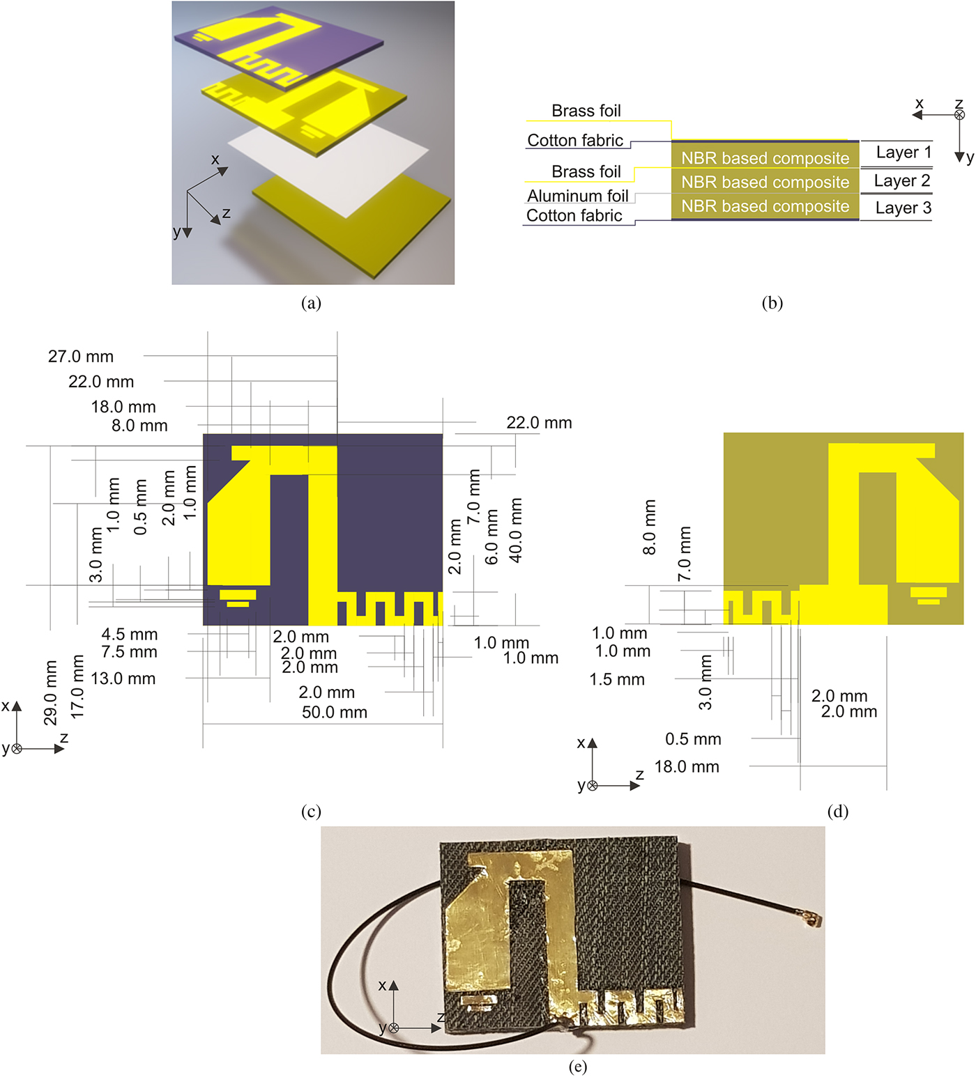
Fig. 2. Configuration of the proposed wearable antenna with optimized dimensions, (a) exploded view, (b) schematic diagram of the multilayer structure and its materials, (c) front view of the top radiating elements on first composite layer, (d) bottom radiating elements placed on the second composite layer, and (e) photograph of the fabricated antenna with a 1.13 mm mini-coax cable (200 mm length), and a U.FL connector.
The proposed antenna was first designed as a modified version of a planar dipole antenna with a rectangular reflector (antenna 1, Fig. 3) for the frequency range of 2.40–2.48 GHz (ISM 2.45 GHz), and subsequently step-by-step developed into a dual-band antenna to cover the frequency ranges of 2.4–2.7 GHz (ISM 2.45 GHz and LTE 2.6 GHz) and 5.150–5.725 GHz (WLAN 5.5 GHz). Figure 3 illustrates steps in the proposed antenna design and plots the simulated reflection coefficient magnitudes versus frequency. For the case of antenna 1 (a planar dipole antenna with a rectangular reflector), several peaks appear over the frequency band at about 2.2, 3.3, 3.7, and 5.5 GHz with narrow bandwidths. As shown in Fig. 3, by adding the meandered lines (antenna 2, Fig. 3) three peaks appear with wide frequency bands, which cover ISM 2.45 GHz, LTE 2.6 GHz, and WLAN 5.5 GHz. Finally, the parasitic elements are embedded in the design of antenna 3 (proposed antenna) to improve the antenna resonance frequency for 5 GHz, the impedance matching, and antenna radiation efficiency. The parasitic elements increase the path over which the surface current flows and that eventually results in lowering the resonant frequency. Meanwhile, the parasitic elements decrease the capacitive reactance of the antenna in the frequency range of 4.8–5.0 GHz.

Fig. 3. Simulated |S 11| curves versus frequency for the planar dipole antenna with a rectangular reflector (antenna 1), planar dipole antenna with rectangular reflector and meandered lines (antenna 2), and proposed antenna (a planar dipole antenna with a rectangular reflector, meandered lines, and parasitic elements).
Based on the optimized parameters given in Fig. 2, a prototype for the proposed antenna was fabricated and presented in the following section.
The rubber and rubber-fabric composites were chosen as a multilayer antenna's substrate since they are hydrophobic and exhibit a good balance of mechanical and electromagnetic properties such as flexibility, thermal stability, low permittivity, and low loss tangent over a wide frequency range, as well as and an ease of electromagnetic property modification via loading with different fillers. Hence, embedding a fabric in a rubber composite we protect it from environmental stress while maintaining the flexible and waterproof structure to achieving of a totally garment integrated antenna (e.g.: as a logo, decorative figure, and etc. on clothes). Textile antennas without a waterproof cover are subject to moisture absorption, which can degrade the antenna performance, especially if the antenna substrate is made out of a material that absorbs moisture [Reference Hall and Hao1].
Prototype fabrication
The antenna is fabricated on flexible nitrile butadiene rubber-fabric (NBR-F) and NBR composites with a thickness of 1.5 mm. The NBR-F was chosen for Layers 1 and 3, while NBR was chosen for Layer 2. The formulation of the NBR-based composite in phr (parts in wt per 100 parts in wt of dry rubber) included: NBR (100.0 phr), zinc oxide (3.0 phr), stearic acid (1.0 phr), processing oil (10.0 phr), isopropyl-phenyl-p-phenylenediamine (1.0 phr), N-tert-Butyl2-benzothiazolesulfenamide (0.7 phr), and sulphur (1.5 phr). The elastomer compounds were mixed using an open laboratory two-roll mill. Cotton textile material (selected from common indigo blue jeans) was used as fabric sheet in NBR-F composite due to its porous and good fabric-to-rubber adhesion. NBR-F composite samples were prepared by fitting NBR-based composite in a moulding plate with thickness of 1.5 mm, then fabric sheet was secured onto the rubber surface and then samples were vulcanized in vulcanization optimum, determined according to their vulcanization isotherms (ISO 3417:2010) at 150 °C in an electrically heated vulcanization hydraulic press at 10 MPa using a steel press form. This technique allows creating of waterproof fabric for wearable antenna applications.
The characterizations of NBR-F and NBR properties, such as complex permittivity and tangent of the dielectric loss angle, were carried out at 2.56 GHz using the resonant perturbation method [Reference Chen, Ong, Neo, Varadan and Varadan24]. The measured real part of the relative permittivity of the synthesized NBR-F and NBR composites is 2.91 and 2.75, respectively. The tangent of the dielectric loss angle is 0.050 and 0.035 for NBR-F and NBR, respectively. The radiating elements of the antenna are built using a brass foil (conductivity 1.50 × 10⁷ S/m) with a thickness of 0.05 mm and an aluminum foil (conductivity 3.82 × 07 S/m) with a thickness of 0.011 mm for the reflector. Two different types of conductors (brass and aluminum) with different thicknesses were used in order to meet the requirements for high flexibility and low profile, and due to their good adhesion to rubber. A photograph of the fabricated antenna with a 1.13 mm mini-coax cable (200 mm length), and a U.FL connector is shown in Fig. 2(e).
Simulation and experimental results
Antenna performance
The antenna structure was analyzed and optimized in FS and in on-body conditions in xFDTD (xFDTD, Remcom Inc., State College, PA, USA), a finite-differencetime-domain method (FDTD)-based simulation software. The numerical simulations require a digital representation of the human body to study and optimized the wearable antenna in the context of the body-centric environment. Therefore, for the simulations and measurements of wearable antennas, many different phantoms were proposed as homogeneous (flat phantom [25], elliptical phantom [25]) and heterogeneous (volumetric human phantom as Hugo [26]). In order to evaluate the influence of the human body on the antenna performance and to investigate SAR, a numerical homogeneous flat phantom (NHFP) was used. The NHFP was chosen because have a simpler construction and the exposure can be evaluated using less complex numerical tools [25]. Moreover, the flat phantom provides maximal surface area contact with the device under test and therefore generally gives a conservative estimation of SAR in a real person [25]. The dimensions of the NHFP were 117 mm (length) × 100 mm (width) × 47 mm (height) and electromagnetic parameters were close to a human muscle tissue (real part of the relative permittivity 40.78 and conductivity 2.31 S/m at 2.56 GHz).
A parametric study was conducted to determine the best combination for the dipole arm length and width, the metal plate length, width and location, the segments of the meandered lines length, width and locations and other antenna dimensions in order to achieve an optimal balance between on-body radiation efficiency, impedance bandwidths, and compactness. The optimization of various dimensions of the designed antenna structure was done by varying one parameter and fixing the others. The optimized values of geometric parameters are depicted in Fig. 2. The physical dimensions of the antenna are 40 mm (x) × 4.6 mm (y) × 50 mm (z).
To confirm the simulation results, the fabricated antenna prototype was experimentally tested in FS conditions and mounted on fabricated experimental homogeneous flat phantom (EHFP). The EHFP with dimensions 117 mm (length) × 100 mm (width) × 47 mm (height) was designed and fabricate accordingly to the recipe and technique described in [Reference Yialmaz, Foster and Hao27]. After the phantom mixture had solidified, electromagnetic properties measurement was carried out by the resonant perturbation method. The measured real part of the relative permittivity of the EHFP is 40.78 and conductivity is 2.31 S/m at 2.56 GHz.
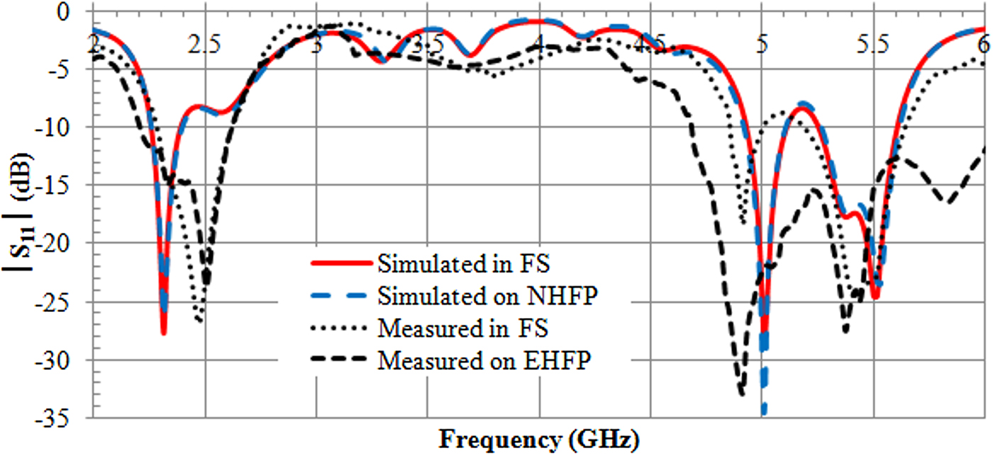
Figure 4 shows the simulated and measured reflection coefficient magnitudes of the proposed antenna in FS and mounted on the NHFP and EHFP. A −6 dB |S 11| reference level (voltage standing wave ratio ≤ 3) is used to define impedance bandwidths, which is practically accepted for LTE mobile phone/notebook applications [Reference Su and Hsieh23] and BCWCs. In the FS the antenna shows the simulated bandwidth of 500 MHz (2.2–2.7 GHz) and 800 MHz (4.9–5.7 GHz) at lower and higher band, respectively. The measured bandwidths are 500 MHz (2.2–2.7 GHz) and 1000 MHz (4.65–5.75). Also Fig. 4 shows that the antenna has a robust input impedance matching when it is placed on NHFP or EHFP. This demonstrates that the rectangular reflector isolates well the antenna from the phantom. A bandwidth broadening is observed for measured bandwidth in the higher band as compared with the FS case, showing a bandwidth extending from 4.65–5.75 GHz to 4.5–6.0 GHz, due to the lossy material phantom loading. These characteristics meet the required bandwidth specifications of ISM 2.45 GHz, LTE 2.6 GHz, and WLAN 5.5 GHz in both FS and on-body. However, there is a difference in the ïS 11ï characteristics between the simulated and the measured results. This difference is primarily attributed to fabrication and assembly inaccuracies. There is small air filling between different layers of the substrate due to the fact that rubber layer is not completely adhered to the rubber-fabric layers. This mistake can be solved by using more accurate manufacture process. Moreover, the coaxial cable and U. FL connector were not integrated into the FDTD simulations which also lead to a difference between the simulations and measurements.

Fig. 4. Simulated and measured |S 11| curves versus frequency of the proposed antenna in free space, on a numerical homogeneous flat phantom (NHFP) and on a fabricated experimental homogeneous flat phantom (EHFP).
Figure 5 presents the simulated and measured normalized 2D radiation patterns of the proposed antenna in FS at the frequencies of 2.44, 2.66, and 5.50 GHz the central frequencies of ISM 2.45 GHz, LTE 2.6 GHz, and WLAN 5.5 GHz, respectively. The amplitude unit used in all plots is dB. The radiation patterns in the xy- and yz-planes at 2.66 GHz are nearly identical with the patterns at 2.44 GHz. From Fig. 5(e), it can be observed that when the frequency is increased (at 5.5 GHz) the maximum radiation direction shifts to 40°~50° in xy-plane. Moreover, at 2.44 and 2.66 GHz, the antenna has a unidirectional and nearly linearly polarized pattern. At 5.5 GHz, the amplitudes of co- and cross-polarized are in the same order, because the size of the antenna is relatively large compared with a quarter of a wavelength. The simulated and measured normalized radiation patterns when the antenna is placed on the surface of NHFP and EHFP are shown in Fig. 6. The results indicate that the shape and direction of the radiation patterns did not shift when the antenna is placed on the phantom. Moreover, the presence of the phantom does not significantly change the cross-polarization levels, and the antenna remains linearly polarized in the on-body scenario at 2.44 and 2.66 GHz. The measured radiation patterns correspond well to simulation predictions with only slight discrepancies.

Fig. 5. Simulated and measured normalized radiation patterns for proposed antenna in free space at: (a) 2.44 GHz in xy-plane; (b) 2.44 GHz in yz-plane; (c) 2.66 GHz in xy-plane; (d) 2.66 GHz in yz-plane; (e) 5.50 GHz in xy-plane, and (f) 5.50 GHz in yz-plane.
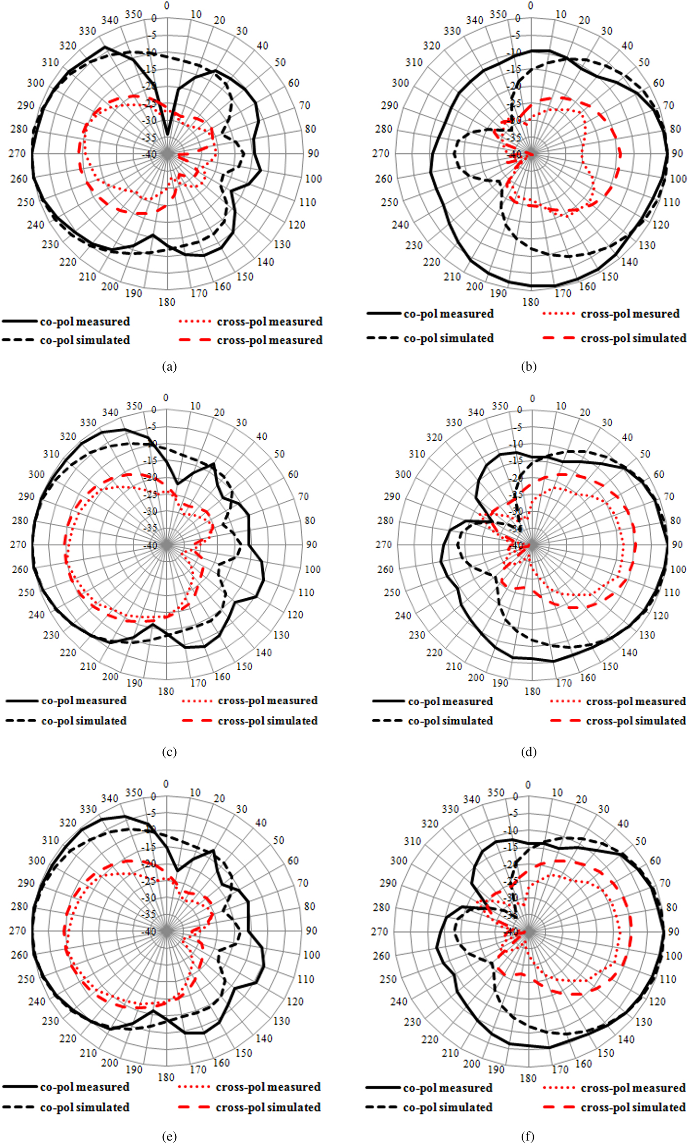
Fig. 6. Simulated and measured normalized radiation patterns for proposed antenna on NHFP and EHFP at: (a) 2.44 GHz in xy-plane; (b) 2.44 GHz in yz-plane; (c) 2.66 GHz in xy-plane; (d) 2.66 GHz in yz-plane; (e) 5.50 GHz in xy-plane, and (f) 5.50 GHz in yz-plane.
The simulated in FS and on-body maximum gain and radiation efficiency are plotted in Fig. 7. Over the lower (Fig. 7(a)) and higher (Fig. 7(b)) bands in FS, the maximum gain is about 0.5–1.5 dBi and 0.7–1.7 dBi with an antenna efficiency 27–35% and 33–45%, respectively. For the maximum gain and antenna efficiency of the proposed antenna with phantom, the simulated results show that the maximum gain is about 0.5–1.5 dBi and the efficiency is decreased to 21–27% at the lower band (Fig. 7(a)). At the higher (Fig. 7 (b)) band both the gain and antenna efficiency are decreased to about −0.5–2.1 dBi and 20–27%, respectively. This signifies that the antenna is able to maintain a high efficiency when positioned on NHFP.
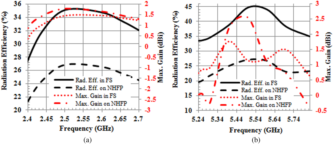
Fig. 7. Simulated radiation efficiency and maximum gain in the free space and on the NHFP for (a) lower (ISM 2.45 GHz and LTE 2.6 GHz), and (b) higher (WLAN 5.5 GHz) bands.
The measured maximum gains in FS and on the EHFP at 2.44, 2.66 and 5.50 GHz are summarized in Table 1 and are compared with the simulated. The measurements were performed using the gain transfer method [28] in a laboratory. The discrepancy between the simulated results and the measured ones comes from the fact that measurements are not done in an anechoic chamber, so multipath and loading effects of objects of any kind, including walls, concrete, and so forth, may have some effect and disrupt the measurements.
Table 1. Measured and simulated maximum gain and radiation efficiency for the proposed antenna in free space, on EHFP, and NHFP

a Max. Gain = Maximum Gain.
b RE = Radiation efficiency.
Comparison with published work
To compare with the previously reported wearable antennas, the antenna properties including antenna size, radiation efficiency, and maximum gain in the FS and on-body conditions are listed in Table 2. The table shows that the proposed antenna has smaller dimensions than [Reference Giman, Soh, Jamlos, Lago, Abdullah Al-Hadi, Abdulmalek and Abdulaziz15, Reference Lago, Soh, Jamlos, Shohaimi, Yan and Vandenbosch20, Reference Su and Hsieh23] and lower profile than [Reference Conway, Cotton and Scanlon8, Reference Giman, Soh, Jamlos, Lago, Abdullah Al-Hadi, Abdulmalek and Abdulaziz15, Reference Lago, Soh, Jamlos, Shohaimi, Yan and Vandenbosch20, Reference Su and Hsieh23]. In addition, the proposed antenna has better radiation efficiency in FS than [Reference Sundarsingh, Kanagasabai and Ramalingam19], better radiation efficiency than [Reference Akhoondzadeh-Asl, Nechayev, Hall and Constantinou22, Reference Su and Hsieh23] and better gain [Reference Lago, Soh, Jamlos, Shohaimi, Yan and Vandenbosch20, Reference Su and Hsieh23] when it is mounted directly on a phantom as a wearable antenna for body-centric communications. However, the proposed antenna has outstanding features as a flexible and waterproof structure to achieving a totally garment integrated antenna as well as simple and low-cost fabrication process.
Table 2. Comparison between the proposed antenna performance and other reported antennas

a RE = Radiation efficiency.
b Max. Gain = Maximum gain.
SAR analysis
The impact of the wearable antenna on human tissue, characterized by the SAR, was also investigated. The 12-field components approach was used to calculate SAR using FDTD numerical technique by placing the antenna on the surface of NHFP. The results presented in Fig. 8 were normalized to net input power of 100 mW. As Fig. 8 shows, for the considered input power, the proposed antenna generates a maximum 1 g average SAR of 0.428 W/kg at 2.62 GHz (Fig. 8(a)) and 1.87 W/kg at 5.24 GHz (Fig. 8(b)). Further evaluation of the 10 g average SAR shows that the maximum values are smaller than 0.165 W/kg for lower (Fig. 8(a)) and smaller than 0.520 W/kg for higher (Fig. 8(b)) bands and are far below the maximum allowed value of 2 W/kg as required by the Institute of Electrical and Electronics Engineers (IEEE) Standard C95.1-2005 [28] and International Commission on Non-Ionizing Radiation Protection (ICNIRP) [29]. It can be observed that, for the targeted frequency bands, the whole-body-average SAR are smaller than 0.015 W/kg for the lower (Fig. 8(a)) and smaller than 0.026 W/kg for the higher (Fig. 8(b)) bands, well below the 0.08 W/kg specification provided by the IEEE Standard C95.1-2005 [28].
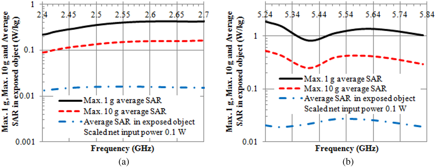
Fig. 8. Plots of the maximum of 1 g, 10 g average SAR and average SAR in the exposed object of the proposed antenna as a function of the frequency for (a) lower (ISM 2.45 GHz and LTE 2.6 GHz), and (b) higher (WLAN 5.5 GHz) bands.
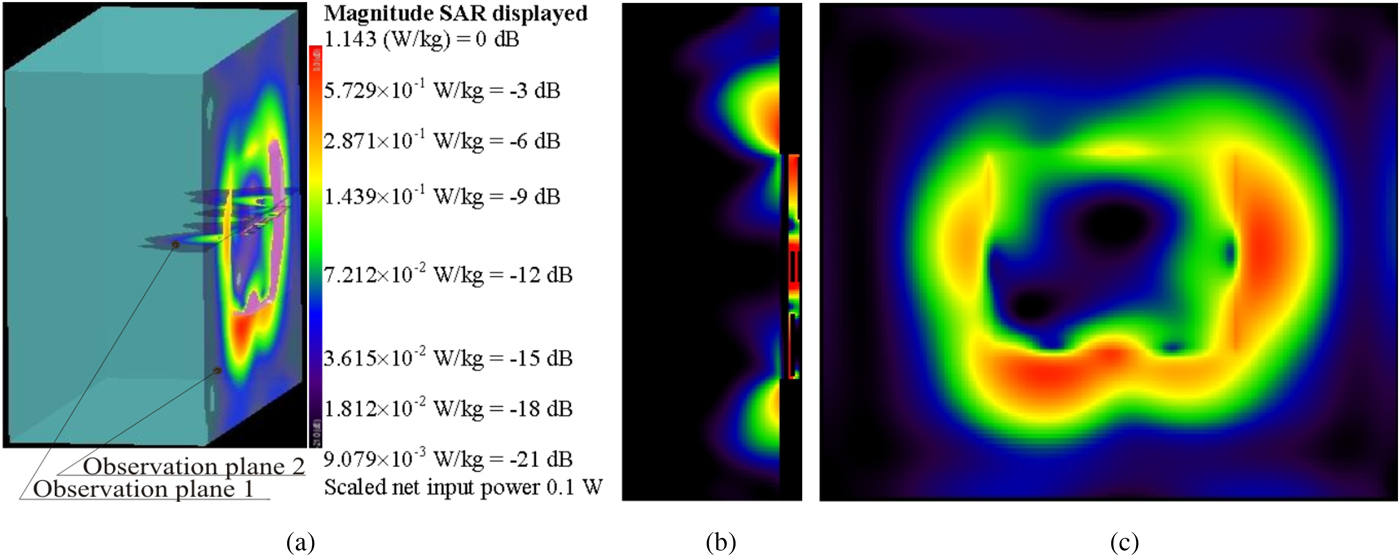
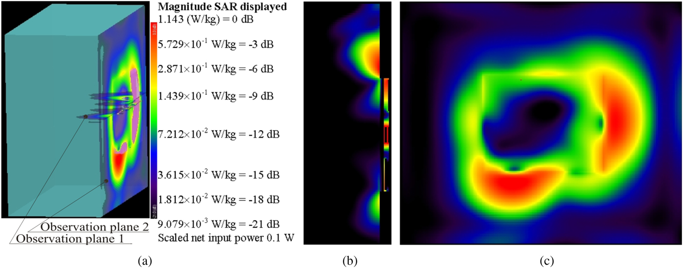
Figures 9–11 show the SAR distributions on the surface of NHFP at the 2.44, 2.54, and 5.50 GHz, respectively. As can be seen in the figures, the main peak SAR occurs in the region near the antenna edges, while the SAR at the surface of NHFP underneath the antenna is considerably reduced (between 9 and 21 dB at 2.44 and 2.54 GHz, and between 3 and 21 dB at 5.5 GHz). This occurs because the reflector and Layer 3 of substrate lie between the antenna and the phantom, providing some degree of shielding from exposure.

Fig. 9. SAR distribution at 2.44 GHz in the NHFP when the proposed antenna is placed on the surface of phantom: (a) observation planes, (b) SAR distribution for the observation plane 1, and (c) SAR distribution for the observation plane 2.

Fig. 10. SAR distribution at 2.54 GHz in the NHFP when the proposed antenna is placed on the surface of phantom: (a) observation planes, (b) SAR distribution for observation plane 1, and (c) SAR distribution for observation plane 2.
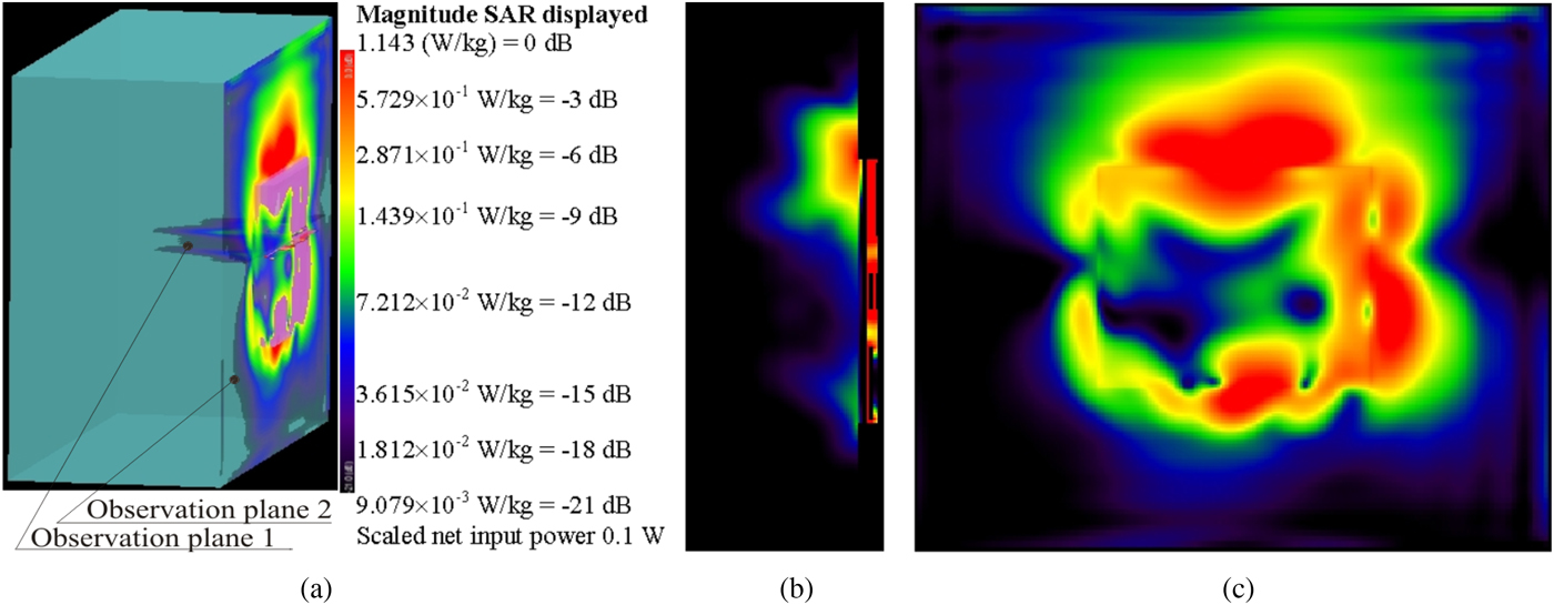
Fig. 11. SAR distribution at 5.50 GHz in the NHFP when the proposed antenna is placed on the surface of phantom: (a) observation planes, (b) SAR distribution for the observation plane 1, and (c) SAR distribution for the observation plane 2.
The presented results in Figs 9–11 also show that the diffraction from antenna edges is more marked at 5.50 GHz compared with 2.44 or 2.54 GHz. This leads to an increment of SAR approximately with 33% in whole exposed phantom (Fig. 8). From Figs. 9(b)–11(b) it can be concluded that by increasing the frequency, asymmetrical radiation from the left and right edges of the antenna increases.
Conclusion
In this paper, a dual-band compact low-profile antenna for wearable applications was designed. The designed antenna was fabricated and measured. Simulated and measured results show that the impedance bandwidth covers the ISM 2.45 GHz, LTE 2.6 GHz, and WLAN 5.5 GHz. Presented results of radiation efficiency, peak gain, and radiation patterns show very good performance in FS conditions, when the antenna was mounted on the tissue-equivalent phantom. Moreover, the proposed antenna exhibits small peak 1 g and 10 g average SAR within the targeted frequency bands and radiation efficiency of more than 21%. Hence, the proposed antenna can be widely applied in wearable devices for body-centric wireless communications in ISM 2.45 GHz, LTE 2.6 GHz, and WLAN 5.5 GHz bands.
Acknowledgement
The authors would like to acknowledge the support of King Khalid University for this research through a grant RCAMS/KKU/003-16 under the Research Center for Advanced Materials Science at King Khalid University, Saudi Arabia and the University of Chemical Technology and Metallurgy, Sofia, Bulgaria
 Abdullah G. Al-Sehemi is a Professor in the department of chemistry King Khalid University, Saudi Arabia. He received his Ph.D. from University of Leicester, UK. He is currently Member of the Saudi Consultative Council. He was the Dean of Scientific Research and director of The Research Center for Advanced Materials Science (RCAMS). He is the author of over 200 publications, co-inventor of several patents and the editor of six books. He is working experimentally and computationally in the field of advanced functional materials, nanomaterials, stereochemistry, and drug design.
 Ahmed A. Al-Ghamdi is a staff member at King Abdul Aziz University (KAU), Faculty of Science, Physics Department. He obtained his B.Sc. in Physics from KAU at 1981 and M.Sc. degree in 1985 from Tulane University, USA. The Ph.D. degree was obtained in 1990 from Sussex University, UK, in point defects created by ion implantation. He has 26 years of experience in academic and research activities in solid-state physics. He worked in the various field of solid physics applications including photodiodes, gas sensors, biosensors, and various another field of applications. He is currently working on synthesis, characterization, and applications in composites and nanocomposites.
 Nikolay T. Dishovsky received the Ph.D. degree from the University of Chemical Technology and Metallurgy, Sofia, in 1983 and the Doctor of Science Degree from the same university in 1997. Since 2000 he is a full professor and head of the department of Polymer engineering at the University of Chemical Technology and Metallurgy. He is the author of eight books, more than 230 articles and more than 45 patents for inventions. Prof. Dishovsky was a recipient of the Bulgarian Patent Office award for the inventor of the year 2015. His research interests include fillers and filled elastomers, rubber-based nanocomposites, rubber-based sensors, and microwave absorbers.
 Nikolay T. Atanasov received the M.Sc. and Ph.D. degrees from the Technical University of Sofia, Sofia, Bulgaria, in 1999 and 2013, respectively. He is currently an Associate Professor with the Department of Telecommunications, University of Telecommunications and Post of Sofia, Bulgaria. He is also an Associate Professor with the Department of Communication and Computer Engineering, South-West University “Neofit Rilski”, Blagoevgrad, Bulgaria. His research interests include computational electrodynamics, SAR computation, and design of antennas for wireless devices, medical diagnostic, and therapeutic applications of EM. He is particularly interested in the characterization of the electromagnetic properties of materials at microwave frequencies and investigation of the potential of conductive composites for antenna applications.
 Gabriela L. Atanasova received the M.Sc. and Ph.D. degrees from the Technical University of Sofia, Sofia, Bulgaria, in 1999 and 2013, respectively. Since June 2000, she has been with the University of Telecommunications and Post of Sofia, Bulgaria, where she is currently an Associate Professor with the Department of Telecommunications. She is also an Associate Professor in the Department of Communication and Computer Engineering, South-West University “Neofit Rilski”, Blagoevgrad, Bulgaria. Her research interests encompass theoretical and experimental studies for modeling interactions between EM fields and biological systems, as well as methods for the computer-aided analysis and design of high-frequency structures and antennas for body-centric communications, WLAN, WSN applications, etc.