


Introduction
The fast development of multi-service wireless communication technology often requires multi-band microwave devices. Therefore, multi-band bandpass filters (BPFs) have attracted much attention for supporting multiple communication applications in a single system, where different frequency bands satisfy the requirement of different standards. Up to now, various methods have been applied to design multi-band BPFs, which include combining several BPFs [Reference Li, Wang, Su and Liang1–Reference Chen and Chu4], stepped-impedance resonators (SIRs) [Reference Liu, Wang, Wang, Lei, Xu, Zhao, Ren and Guan5–Reference Li and Zhang8], and stub-loaded resonators (SLRs) [Reference Zhang and Zhao9–Reference Chu, Chen, Tu and Wang11]. In [Reference Li, Wang, Su and Liang1], the tri-band BPF is composed of eight sets of resonators, and the center frequencies can be easily placed in the proper position. In [Reference Chen, Weng and Chang7, Reference Li and Zhang8], SIRs are employed to provide more freedom to control the harmonics, and a 0° feeding structure is presented to improve the passband selectivity. In [Reference Gao and Zhang10], SLR provides the sufficient coupling freedom of adjustment, so the filter exhibits the excellent performance of controllable center frequencies and passband bandwidths.
Although above-mentioned filters have fully demonstrated their own merits, it is difficult to meet the requirement of high data rate, high transmission capacity, and multi-service in modern communication systems, owing to the significant drawback of limited bandwidths. Therefore, the BPFs with relatively wide bandwidths are required. Recently, in [Reference Deng, Zhao, Zhou, Fu and Liu12], a triple-wideband filter with compact size and high selectivity is produced by using three sets of resonators. In [Reference Xue, Gao and Zhang13], a miniaturized triple-wideband filter consisting of two short-SLRs is proposed. However, they are unable to independently control three passband bandwidths, which reduces the design flexibility. There is no doubt that the triple-wideband BPFs with controllable bandwidths are more competitive in communication application.
In this article, a triple-wideband BPF with controllable bandwidths utilizing two multi-mode stub-loaded resonators (MMSLRs) and a triple-mode resonator (TMR) is proposed. Each passband of the BPF is consisted of four resonant modes, which result in sufficient bandwidths, and the highest passband covers the 5G WiFi band. The even- and odd-mode analysis technique is applied to interpret the resonant characteristics of the MMSLR and the TMR. The bandwidths of the proposed filter can be individually controlled by adjusting the lengths of open-ended stubs.
Resonator analysis
A triple-wideband BPF is designed in this paper. The center frequencies of the three passbands are initially designed at 2.6, 3.6, and 5.4 GHz, respectively, with the 3 dB fractional bandwidth (FBW) above 15% for each passband. Based on the target specifications, the MMSLR and TMR are selected to design the tri-band filter.
The physical layout of the MMSLR is sketched in Fig. 1(a), which is formed by adding two identical open-ended stubs, denoted by length L 2 at both sides and another T-shaped stub, denoted by length L 4 + L 5, at the center plane. Owing to its symmetrical structure, the operating mechanism can be described by the even- and odd-mode analysis method.

Fig. 1. (a) Physical layout of the proposed MMSLR, (b) odd- and (c) even-mode equivalent circuits of (a).
For odd-mode excitation, the equivalent circuit can be obtained as shown in Fig. 1(b). In order to simplify the analysis, the characteristic admittance of the widths W 1, W 2, W 3, W 4/2, and W 5 is Y, and the electrical lengths of the five sections with lengths L 1, L 2, L 3, L 4, and L 5 are θ 1, θ 2, θ 3, θ 4, and θ 5, respectively. The input admittance Y in−odd of the odd-mode equivalent circuit is expressed as
 $$Y_{in - odd} = jY\displaystyle{{\tan \theta _1 + \tan \theta _2 - \cot \theta _3} \over {1 - \tan \theta _1 (\tan \theta _2 - \cot \theta _3 )}}.$$
Similarly, the input admittance Y in−even of the even-mode equivalent circuit in Fig. 1(c) can be expressed as
 $$Y_{in - even} = jY\displaystyle{{\tan \theta _1 + \tan \theta _2 + \tan (\theta _3 + \theta _4 + \theta _5 )} \over {1 - \tan \theta _1 [\tan \theta _2 + \tan (\theta _3 + \theta _4 + \theta _5 )]}}.$$
By setting Y in−odd = 0 and Y in−even = 0, the odd- and even-mode resonant conditions can be summarized as
 $$\tan \theta _1 + \tan \theta _2 - \cot \theta _3 = 0,$$
 $$\tan \theta _1 + \tan \theta _2 + \tan (\theta _3 + \theta _4 + \theta _5 ) = 0.$$
It is observed that the odd-mode resonant frequencies are affected by L 1, L 2, and L 3, while the even-mode resonant frequencies can be controlled by tuning L 1, L 2, L 3, L 4, and L 5. Thus, adjusting the T-shaped stub (L 4 + L 5) is an effective method to distinguish the odd and even modes. For validation, the resonant modes are simulated in Advanced Design System 2011.10 (ADS).
As shown in Fig. 2(a), with the increase of length L 5, the resonant frequency f e1 decreases in a wide range, and f e2 changes a little, whereas the resonant frequencies f o1 and f o2 keep unchanged. In addition, if wider frequency range is considered, the another even-mode f e3 is also introduced. The two MMSLRs have the similar structure, but provide different number of resonant modes due to the choice of different frequency range, so the first MMSLR produces five modes and the second MMSLR generates four modes in this paper. It can also be observed from Fig. 2(b) that the stub length L 2 brings the resonant frequencies f o2 and f e2 closer together while f o1 and f e1 remain unchanged. Thus, the bandwidth of the first MMSLR can be tuned by adjusting the lengths L 2 and L 5.

Fig. 2. (a) Simulated |S 21| against L 5, and (b) resonant frequencies versus L 2.
The schematic diagram of the TMR is presented in Fig. 3(a), which is constructed by two folded open-ended stubs at both sides. For analysis simplicity, the characteristic admittance of the widths W 1, W 2, and W 3 is Y, and the electrical lengths of the lengths L 31, L 32, and L 33 are θ 1, θ 2, and θ 3, respectively. Since the structure is symmetrical, even- and odd-mode analysis method can be applied to explain its resonant characteristics. The input admittance of the odd- and even-mode equivalent circuits shown in Figs 3(b) and 3(c) can be expressed as
 $$Y_{in - odd} = jY\displaystyle{{\tan \theta _1 - \cot \theta _2 + \tan \theta _3} \over {1 + \tan \theta _1 \left( {\cot \theta _2 - \tan \theta _3} \right)}},$$
 $$Y_{in - even} = jY\displaystyle{{\tan \theta _1 + \tan \theta _2 + \tan \theta _3} \over {1 - \tan \theta _1 \left( {\tan \theta _2 + \tan \theta _3} \right)}}.$$
Fig. 3. (a) Schematic diagram of the TMR, (b) odd- and (c) even-mode equivalent circuits of (a).
By setting the resonant conditions Y in−odd = 0 and Y in−even = 0, the following equations can be obtained
 $$\tan \theta _1 - \cot \theta _2 + \tan \theta _3 = 0,$$
 $$\tan \theta _1 + \tan \theta _2 + \tan \theta _3 = 0.$$
It can be seen from equations (7) and (8), the odd-mode resonant frequencies and the even-mode resonant frequencies are simultaneously affected by L 1, L 2, and L 3.
In Fig. 4(a), the resonant modes f o4 and f e4 decrease with the length L 32 increasing. In Fig. 4(b), by changing the length L 33, the f o3 can be shifted within a wide range, when f e4 is fixed, and f o4 varies a little. Therefore, the resonant modes of the TMR can be easily adjusted. For the purpose of enlarging the bandwidth, three resonant modes generated by the TMR, together with the fifth resonant mode f e3 of the first MMSLR, form the third passband.

Fig. 4. Simulated |S 21| against (a) L 32, and (b) L 33.
Tri-band BPF design and simulation
Based on the resonator analysis, a tri-band BPF is designed by utilizing the proposed two MMSLRs and a TMR, as shown in Fig. 5. The lower I/O feed line is located between the first MMSLR (in orange) and the second MMSLR (in purple). The two MMSLRs are modified with folded stubs to reduce the size. Because of the special structure of the feed lines, a TMR (in blue) can be added outside the upper I/O feed line. To obtain the proposed triple-wideband BPF, the |S 21| of MMSLR 1, MMSLR 2, and TMR is separately simulated, as shown in Fig. 6, to confirm the initial resonant modes in each resonator. From the simulated results of MMSLR 1, the four resonant modes can be observed in the first passband, and another resonant mode can be observed at the frequency of 5.3 GHz. In addition, this resonant mode and three resonant modes generated by TMR can form the third passband, so the TMR is designed at the right side of 5.3 GHz. The MMSLR 2 generating the second passband is designed between MMSLR 1 and TMR. Then, the circuit model combining three resonators are constructed in ADS to obtain the design lengths of three resonators. Design parameters of the simulated model are given as (unit: mm): L 1 = 15.375, L 2 = 15.625, L 3 = 0.85, L 4 = 9.7, L 5 = 7.45, L 21 = 10.9, L 22 = 12.025, L 23 = 0.625, L 24 = 6.675, L 25 = 4.875, L 31 = 8.3, L 32 = 8.425, L 33 = 1.1, W 1 = 0.1, W 2 = 0.2, S 1 = S 2 = S 3 = 0.1. Next, based on the above design parameters, the simulation tool, which is Sonnet 15.52, is applied to complete the simulation. By adjusting the lengths of stubs and distances between the stubs, the desired frequency responses of the tri-band filter can be obtained.

Fig. 5. Layout of the proposed tri-band BPF.

Fig. 6. Simulated |S 21| of MMSLR 1, MMSLR 2, and TMR, separately.
It can be seen from Figs 7(a) and 7(b), the variation of L 2 and L 5 mainly influence bandwidth of the first passband without affecting the other passbands. In Figs 7(c) and 7(d), it is observed that the lengths L 22 and L 25 change the bandwidth of the second passband, and only have a little change in the third passband, but no effect on the first passband. In Fig. 7(e), it is clear that the length L 32 can only tune the bandwidth of the third passband. Therefore, three passband bandwidths of the filter can be independently controlled, which results in a high design flexibility to build the tri-band BPF.

Fig. 7. Simulated |S 21| against (a) L 2, (b) L 5, (c) L 22, (d) L 25, and (e) L 32.
In Fig. 8, the frequency responses of |S 21| and Z in are investigated [Reference Xiong, Teng, He, Tam, Yu, Choi and Chen14]. Here, Z in1 represents the input impedance of folded open-ended stubs and Z in2 denotes the input impedance of T-shaped stubs, as shown in Fig. 9. If the condition Z in = 0 is satisfied at a proper frequency, a transmission zero will be generated at this frequency, which results from the introduction of virtual ground blocking the transmission of the signals. As an example, the equations from the first MMSLR can be expressed as
 $$Z_{in1} = - jZ_2 \cot \theta _2 = 0,$$
 $$Z_{in2} = - jZ_4 \displaystyle{{Z_5 - 2Z_4 \tan \theta _4 \tan \theta _5} \over {2Z_4 \tan \theta _5 + Z_5 \tan \theta _4}} = 0.$$
Fig. 8. Frequency responses of |S 21| and Z in.

Fig. 9. Ideal model circuit of the MMSLR.
Similarly, this way can be applied in the other two resonators. Through the calculation of the equations, transmission zeros can be determined by the corresponding stubs. It is noted that the transmission zero enclosed by orange box is created by the source–load coupling.
Results and discussion
According to the above analysis, a triple-wideband BPF is designed, fabricated, and measured. The filter is fabricated on a substrate with relative dielectric constant of 3.38, thickness of 0.508 mm, and loss tangent of 0.0027. The dimension parameters used to implement the filter are shown as follows (unit: mm): L 1 = 15.6, L 2 = 15.9, L 3 = 0.5, L 4 = 9.6, L 5 = 6.95, L 21 = 10.05, L 22 = 12.1, L 23 = 0.7, L 24 = 6.5, L 25 = 5.35, L 31 = 7.475, L 32 = 7.7, L 33 = 0.95, W 1 = 0.1, W 2 = 0.2, S 1 = S 2 = S 3 = 0.1. The whole size occupies 25.9 mm × 13.6 mm (excluding the feed lines), which corresponds to 0.38λ g × 0.20λ g, where λ g is the guided wavelength at 2.7 GHz. All the resonators have the uniform width of 0.2 mm, which contributes to an easy design process. The photography of the fabricated filter is shown in Fig. 10.

Fig. 10. Photography of the fabricated filter.
The simulation and measurement are accomplished by Sonnet 15.52 and Agilent E5071C vector network analyzer, respectively. Simulated and measured results of |S 11| and |S 21| are depicted in Fig. 11. The measured results of the proposed filter exhibit excellent agreement with simulated results. The measured center frequencies of the three passbands are located at 2.7, 3.67, and 5.44 GHz, and the minimum insertion losses are 1.2, 2.3, and 1.6 dB, with 3 dB FBWs of 20.1, 14.7, and 26.3%, respectively. The measured return losses are better than 17.6, 18, and 12.2 dB. Five transmission zeros are created at 2.34, 3.14, 4.08, 4.31, and 6.48 GHz, which greatly improves the passband selectivity and stopband suppression. Table 1 lists a comparison between this work and some reported tri-band BPFs. In this work, the proposed tri-band BPF exhibits the better FBW in all the three passbands compared with the referenced tri-band BPFs.
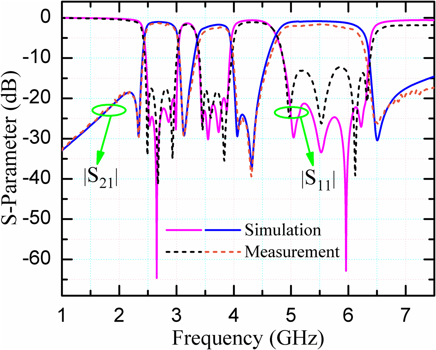
Fig. 11. Simulated and measured results of the proposed filter.
Table 1. Performance comparison with previous tri-band BPFs

Conclusion
This paper presents a triple-wideband BPF based on SLRs. By adjusting the lengths of open-ended stubs, the bandwidths of the three passbands can be controlled individually. In addition, five transmission zeros are created to improve the passband selectivity and stopband suppression. Measured results agree well with the simulated results. The merits of wideband and controllable bandwidths make the proposed tri-band BPF attractive in modern wireless communication system.
Acknowledgements
This work was supported by the National Natural Science Foundation of China (Grant Nos. 51002081, 61171028, 61176119, and 61471208), and the Tianjin Research Program of Application Foundation and Advanced Technology (15JCQNJC01300 and 15JCYBJC46900).
 Li Gong was born in Suzhou, Jiangsu province, China. He received the B.E. degree from Suzhou University of Science and Technology, Suzhou, China, in 2016, and is currently working toward the M.E. degree at Nankai University, Tianjin, China. His main research interests are microwave filters and multiplexers design.
 Yang Xiong was born in Huaihua, Hunan province, China, in 1990. He received the B.Eng. degree from Shandong University of Technology, Zibo, China, in 2013, and is currently working toward the Ph.D. degree at Nankai University, Tianjin, China. His main research interests include microwave circuits design, high-temperature superconducting terahertz devices, and terahertz signals detecting.
 Fan Zhang received the B.E. degree from Nankai University, Tianjin, China, in 2015, and is currently working toward the M.E. degree. His main research interests are microwave filters and multiplexers design.
 LiTian Wang was born in Tianjin, China. He received the B.Eng. degree from Tianjin University of Science and Technology, Tianjin, China, in 2014, and is currently working toward the Ph.D. degree at Nankai University, Tianjin, China. His main research interests include microwave passive components and systems, HTS tunable filters design.
 Yan Sun received the B.E. degree from Hebei GEO University, Hebei, China, in 2017, and is currently working toward the M.E. degree at Nankai University in Tianjin, China. Her main research interest is RF microwave.
 XinJie Zhao received his M.E. degree in Semiconductor Physics from the University of the Inner Mongol, Huhehaote, China, in 1988, and the Ph.D. degree in Material Science from China Institute of Atomic Energy, Beijing, China, in 1999, respectively. Since 2002, he has been a Professor with the Department of Electronics, Nankai University, Tianjin, China. His research interests are in the fields of the applications of high-temperature superconductors, the generation and detection of THz signals, and microwave device.
 Ming He received the M.Eng. and Ph.D. degrees in Electrical Engineering from Nankai University, Tianjin, China, in 2002 and 2008, respectively. Since 1997, he has been with the Department of Electronics, Nankai University, Tianjin, China, where he became a Professor in 2016. From 2004 to 2009, he held several visiting research appointments in Juelich Research Center and Karlsruhe University, Germany. His research interests are in the fields of the applications of high-temperature superconductors, the generation and detection of THz signals, and microwave communications.
 Lu Ji received the Ph.D. degree in Microelectronics and Solid Electronics from Nankai University, Tianjin, China, in 2008. He is currently an Associate Professor at the College of Electronic Information and Optical Engineering, Nankai University. His research interests include the study of high-temperature superconducting films, superconducting electronics, and high-temperature superconducting microwave devices.
 Xu Zhang received the Ph.D. degree in Electrical Engineering from Nankai University, Tianjin, China, in 2008. He is currently an Associate Professor at the College of Electronic Information and Optical Engineering, Nankai University. His research interests include the applications of high-temperature superconductors, superconducting filter, and microwave communications.
 Bo Zhang received the M.S. degree in Optical Engineering in 2015 from Nankai University, Tianjin, China, in 2010. She is currently a Lecturer at the Institute of Modern Optics, Nankai University. Her research interests are mainly focused on optical and microwave information processing.


