


Introduction
Radio frequency identification (RFID) has widely been used to identify various kinds of objects with RFID tags attached to them [Reference Finkenzeller1]. The tags receive RF power transmitted by the reader to power up their internal circuits which send the data back to the reader by means of backscattering. Considering the size of system components, reader antennas are relatively large, and thus difficult to be integrated into the working environment in terms of installation efforts and aesthetic. Therefore, a compact design of reader antennas with a low profile is of great interest. Besides, most of the reader antennas are desired to be circularly polarized in order to cope with the orientation diversity of the tags [Reference Sharma and Tripathi2]. In some cases, a specific radiation pattern is also necessary in order to define the tag-detectable areas or directions. Another important requirement for the reader antenna is the bandwidth regarding impedance matching and axial ratio (AR) to ensure secured communication with the tags. Since the assigned frequency band of the ultra-high frequency (UHF) RFID varies by global regions, a wideband reader antenna covering UHF RFID global bands is advantageous for the manufacturers and system integrators since the product variety can be minimized. Consequently, production and system maintenance can be simplified. According to GS1 – the organization which manages global standards for business communication – the global UHF RFID frequency band is allocated within 860–960 MHz [3]. In European countries, the 866.6 MHz band with a 2 MHz bandwidth is common. For the USA, the 915 MHz band and a bandwidth of 26 MHz are assigned. As the examples of Asian countries, China allocates the 922.5 MHz band and 4 MHz bandwidth for RFID, whereas for Thailand, the frequency band for UHF RFID is at 922.5 MHz with a 5 MHz bandwidth. Thus, most UHF RFID reader antennas in the literature were designed to cover the resonant frequency band from 860 to 960 MHz. If all requirements regarding bandwidth, polarization, radiation pattern, and compact size must be fulfilled, designing the reader antenna is a very challenging task [Reference Lau, Chu and Wu4].
State-of-the-art circularly polarized UHF RFID reader antennas in the literature fall into two categories, truncated patch or annular ring antennas [Reference Chen, Qing and Chung5–Reference Pan, Zheng, Liu, Wang and Li9] and quadrifilar antennas [Reference Zhao, Huang, Li, Zhang and Wen10–Reference Lee, Lee, Jang, Tae and Yu15]. Truncated patch antennas generate circular polarization by truncation of the square patch's corners in one of the diagonals. Whereas the antenna from [Reference Chen, Qing and Chung5] utilized multiple probe feeds at different positions for the 90° phase shift to enhance the AR bandwidth, [Reference Wang, Fang, Fu and Jia6] and [Reference Wang, Fang, Fu and Fan7] feature meander line feeds to enhance the impedance bandwidth with a simpler feed structure. In contrast to [Reference Wang, Fang, Fu and Fan7], the antennas from [Reference Chen, Qing and Chung5, Reference Wang, Fang, Fu and Jia6] comprise an additional parasitic patch to enhance the bandwidth. The parasitic patch must also be truncated and mounted over a certain air gap on top of the main radiator. This design can fulfill bandwidth requirements in terms of impedance matching and AR at the cost of structural complexity. The high gain of more than 8 dBic of these antennas was realized at the cost of a relatively large reflector area (250 × 250 mm2). With the need for multiple layers and air substrates, the overall volume of these antennas is relatively large. In general, the transmitted power of RFID readers can be set by the reader's control software. In case of such high gain antennas, the reader's power must be reduced to be in compliance with the limited effective isotropic radiated power or effective isotropic radiated power values according to Federal Communication Commission (FCC), European Telecommunications Standards Institute (ETSI), or other regulations.
The antenna from [Reference Chen, Fu, Gong, Yan and Zhao8] with low profile applied an annular ring structure instead of a truncated patch. Despite the adoption of a stacked parasitic element to improve the impedance and AR bandwidth, the antenna could not cover the global UHF RFID frequency band. Moreover, the ground plane of this antenna was relatively large with the area of 250 × 250 mm2. Compared to [Reference Chen, Qing and Chung5] and [Reference Wang, Fang, Fu and Jia6], the truncated patch antenna from [Reference Pan, Zheng, Liu, Wang and Li9] placed the bandwidth-enhancing parasitic element on the same layer with the main patch. The bandwidth and gain of this antenna are impressive at the cost of a typical large ground plane. If lower antenna gain is acceptable, the size of the antenna can be reduced. In the case of wideband UHF RFID reader antenna with unidirectional pattern, quadrifilar antennas with four radiator elements and a feed network have been reported in the literature [Reference Zhao, Huang, Li, Zhang and Wen10–Reference Lee, Lee, Jang, Tae and Yu15]. The feed network divides the input power equally before feeding to each radiator element with a sequential 90° phase shift to generate the circular polarization. Contrary to the truncated patch or ring with a large reflector, quadrifilar antennas use a common ground plane of the inverted-F elements and the power-splitting feed network to enable a directional radiation pattern. This design concept features a compact size, a low profile, and a large impedance bandwidth. Among state-of-the-art UHF RFID quadrifilar antennas, the design from [Reference Zhao, Huang, Li, Zhang and Wen10] and [Reference Liu, Shen, Liu, Wu, Su and Liu14] provide the largest impedance and AR bandwidth which can cover the global UHF RFID frequency band. The peak gain of [Reference Pan, Zheng, Liu, Wang and Li9] is observed at 915 MHz with 2.6 dBic, whereas at the lower and upper band limits of 860 and 960 MHz, the gain is drastically decreased to −4.4 and −1.8 dBic, respectively. In comparison, the designs from [Reference Son, Lee, Lee, Min and Yu11–Reference Son, Lim, Lee, Min and Yu13] and [Reference Lee, Lee, Jang, Tae and Yu15] provide smaller bandwidths, especially regarding the AR which are not sufficient to cover the global UHF RFID band.
In order to stabilize the gain while fulfilling other requirements including impedance matching and AR over the global UHF RFID band, this paper presents a compact circularly polarized quadrifilar antenna based on a phase-shifting feed network and four planar inverted-F antenna (PIFA) elements. The proposed antenna including the PIFA and all feeding elements have been made from a low-cost FR-4 substrate (ɛr = 4.4, loss tangent = 0.02, thickness = 1.6 mm). The PIFA elements can easily be constructed by cutting the FR4 sheet to different patterns before assembling all the parts together. The feed network, also fabricated on an FR4 substrate, comprises a two-stage Wilkinson power divider and delay lines of different lengths to create the phase shift. The overall size of the antenna is 120 × 120 × 13.2 mm3 with a peak gain of 3.75 dBic and a directional radiation pattern. The proposed design offers excellent impedance and AR bandwidth covering the global UHF RFID band. The gain variation over the entire bandwidth of 1 dB is lower than state-of-the-art quadrifilar antenna for RFID readers reported in the literature.
Antenna design and fabrication
The proposed design is shown in Fig. 1 consisting of four radiators and a feed network fabricated using an FR-4 substrate. In contrast to quadrifilar antennas for UHF RFID readers based on inverted-F elements reported in the literature, the proposed antenna adopts the PIFA structure (https://en.wikipedia.org/wiki/Inverted-F_antenna) as the radiators in order to enhance the bandwidth. The PIFA elements consist of the main radiating plate with the dimensions 25 × 65 × 1.6 mm3, a shorting plate with the size of 8 × 11.6 × 1.6 mm3 and the feeding plate with the size of 3 × 11.6 × 1.6 mm3. The PIFA elements were made by cutting the main radiators, the shorting and the feeding plates from an FR4 printed circuit board (PCB) with a single copper layer to the sizes as aforementioned.
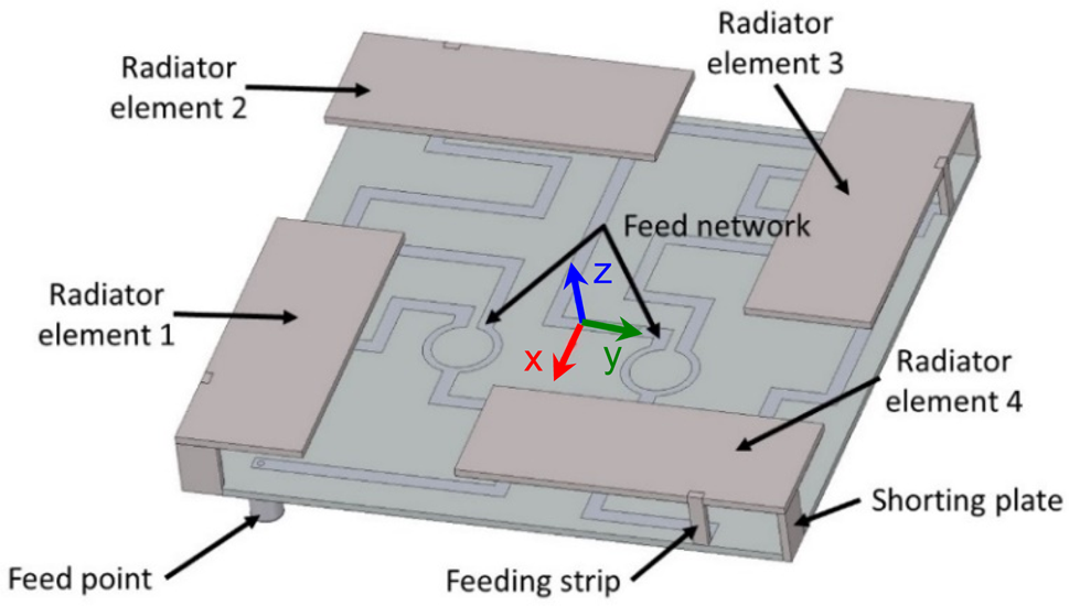
Fig. 1. Configuration of the proposed antenna.
Then, these elements were assembled together to construct the radiator as shown in Fig. 2. The feed network is a microstrip two-stage Wilkinson divider fabricated on an FR4 PCB with the dimensions of 120 × 120 × 1.6 mm3 (see Fig. 3). Each output port of the feed network was designed to provide the same signal power with a sequential phase shift of 0°, 90°, 180°, and 270°. The phase shifts were realized by different lengths of the delay lines at the output ports of the divider. The PIFA radiators were then assembled to the microstrip feed network by soldering their feed points to the outputs of the divider. The PIFA radiators are located ca. 10 mm above the feed network so that the overall size of the antenna is 120 × 120 × 13.2 mm3. The total height of 13.2 mm results from the distance between the feed network and the radiator plus two times of the PCB thickness of 1.6 mm. The input of the divider is the main feed point of the proposed antenna. This feed point is constructed using a 50 Ω SMA connector soldered to the signal path and the ground at the backside of the circuit board.

Fig. 2. Geometry of the PIFA radiator element.

Fig. 3. Feed network comprising two-stage Wilkinson power divider and delay lines with geometric parameters.
All geometrical parameters of the proposed antenna have been studied and optimized using Ansys HFSS. The radiators were originally designed to resonate at the center frequency of 900 MHz. By optimizing the widths of the radiator and the shorting plate as well as the feed position of the PIFA radiator, the gain and the impedance bandwidth have been optimized for the best performance. For the entire antenna including the PIFA elements and the feed network, the AR bandwidth was optimized while maintaining the gain and the impedance bandwidth. To achieve the circular polarization, equal power distribution and a sequential 90° phase shift among the radiator elements must be ensured.
Figures 4 and 5 show the simulation results of the power distribution and the phases of the output signals of the feed network, respectively. The input of the feed network is defined as port 1 whereas ports 2–5 are the output ports. Figure 4 shows the Wilkinson divider with two 100 Ω balancing impedances. The power distribution among the ports shows a variation around 1.5 dB within the bandwidth of interest. The input matching is ensured with a reflection coefficient lower than −20 dB over the required bandwidth. Figure 5 confirms the 90° phase difference among the four output ports feeding to the PIFA radiators at 900 MHz. The phase difference is decreased as the frequency is decreased and increased as the frequency is increased due to the change of the delay lines' electrical lengths. However, within the required frequency band, this change is relatively small so that the circular polarization can still be achieved. After the overall optimization, the proposed antenna was fabricated. A photograph of the proposed antenna is shown in Fig. 6. The top layer of the radiators is an FR4 layer, whereas the copper layer is on the radiator's backside to simplify the soldering and construction.

Fig. 4. Simulated S-parameters of the Wilkinson power divider.

Fig. 5. Simulated phase change over the frequency of the feed network's output signals.

Fig. 6. Photograph of the antenna prototype.
Results and discussions
After the design and optimization of the PIFA elements and the feed network, the overall antenna structure was again simulated. The surface current on the PIFA elements with the input signal's phase of 0° and 90° is shown in Figs 7(a) and 7(b), respectively, for the lower band of 860 MHz. It can be observed that the PIFA elements 2 and 4 (see Fig. 1) are active with 0°, whereas the elements 1 and 2 are active with 90°. At the upper band of 960 MHz, the elements 1, 2, and 4 are active with 0° as shown in Fig. 8(a). As the phase is changed to 90°, the surface current pattern is rotated so that the elements 1, 2, and 3 are active as shown in Fig. 8(b). The simulated surface current confirms that the circular polarization is ensured for the entire bandwidth from 860 to 960 MHz. The input reflection coefficient of the antenna's external SMA port is shown in Fig. 9. Despite discrepancies of the simulated and measurement results which have probably been caused by the fabrication inaccuracy, the matching is excellent with a reflection coefficient lower than −15 dB over the entire bandwidth. The simulated and measured gain is plotted in Fig. 10. Similar to the reflection coefficient, simulated and measurement results show some differences. However, the measurement shows that the fabricated antenna can provide a maximum gain of 3.75 dB with a gain variation over the bandwidth of 1 dB. Regarding the AR, the simulation shows an in-band maximum AR of 1.4 dB at the upper and lower bands, whereas the measurement shows an AR of lower than 1 dB over the entire bandwidth (see Fig. 11).

Fig. 7. Surface current at 860 MHz with the input signal's phase: (a) 0° and (b) 90°.

Fig. 8. Surface current at 960 MHz with the input signal's phase: (a) 0° and (b) 90°.

Fig. 9. Input reflection coefficient of the proposed antenna.

Fig. 10. Simulated and measured gain of the proposed antenna.

Fig. 11. Axial ratio of the proposed antenna.
The antenna prototype was measured in an anechoic chamber (see Fig. 12). The measured radiation patterns are shown in Fig. 13 for the x–z plane and Fig. 14 for the y–z plane at 860, 900, and 960 MHz, respectively. The differences between the simulated and the measured radiation patterns could originate from the effect of the antenna fixture mounted on the anechoic chamber's turn table. The antenna provides a directional radiation pattern according to the design goal. The measured AR over the azimuth angle at 900 MHz is shown in Fig. 15 with a 3 dB AR beamwidth of 130.6° for the x–z plane and 95° for the y–z plane.

Fig. 12. Measurement of the proposed antenna in an anechoic chamber.

Fig. 13. Simulated and measured radiation patterns of a proposed antenna in the x–z plane at (a) 860, (b) 900, and (c) 960 MHz.

Fig. 14. Simulated and measured radiation patterns of a proposed antenna in the y–z plane at (a) 860, (b) 900, and (c) 960 MHz.

Fig. 15. Measured AR of the proposed antenna as a function of the azimuth angle at 900 MHz.
Table 1 shows a comparison of the proposed antenna's performance with related works from the literature. The proposed antenna offers a good combination of relatively compact size, simple fabrication, relatively high gain, and very large impedance matching as well as AR bandwidth with a directional pattern. The gain variation over a bandwidth of 1 dB provided by the proposed antenna is the lowest compared to state-of-the art quadrifilar antennas from [Reference Zhao, Huang, Li, Zhang and Wen10–Reference Lee, Lee, Jang, Tae and Yu15]. In the last column, the relative size of each antenna is provided. This is calculated by dividing the largest dimension a of each antenna by the wavelength λ at the center frequency of the antenna. Compared to the antenna from [Reference Liu, Shen, Liu, Wu, Su and Liu14] with a comparable gain, our proposed antenna is slightly larger whereas the bandwidth and gain flatness are greater. Compared to a conventional directional RFID reader antenna with a 250 × 250 mm2 reflector from [Reference Chen, Qing and Chung5, Reference Wang, Fang, Fu and Jia6, Reference Chen, Fu, Gong, Yan and Zhao8], the antenna area can be reduced by a factor of 1 – (120 × 120)/(250 × 250) or 77% in our case.
Table 1. Comparison of UHF RFID reader antennas from the literature with the proposed antenna

Parameter studies
In this section, parameter studies are shown with detailed information about the effects on S-parameters and gain caused by the variation of geometrical parameters of the PIFA elements. The studies include the variation of width, length, and height as well as width of the shorting plate and its distance to the PIFA feed point. Figure 16 shows the input reflection coefficient at the feed port of the radiator element 1 (see Fig. 1) as the width of the PIFA element was varied from 25 to 29 mm whereas the length was fixed at 65 mm. It is obvious that with the increasing width of the PIFA elements, the resonant frequency is decreased. The input reflection coefficients of the radiator elements 2–4 are not shown to limit the length of the paper. However, a similar trend was observed compared to the radiator element 1. By feeding all radiator elements with the sequential 90° phase shift and the same signal power, the total gain is shown in Fig. 17 with the effect of the element's width on the total gain of the antenna. The gain is stable and optimized over the entire bandwidth with the width of 25 mm. Then, the width was fixed at 25 mm, whereas the length of the PIFA elements was varied. The effects of this variation on the input reflection coefficient and the gain are shown in Figs 18 and 19, respectively. As expected, the resonant frequency is decreased with the increasing length of the element. According to the simulation results in Fig. 19, the optimal length of the element is 65 mm considering the gain flatness over the bandwidth.
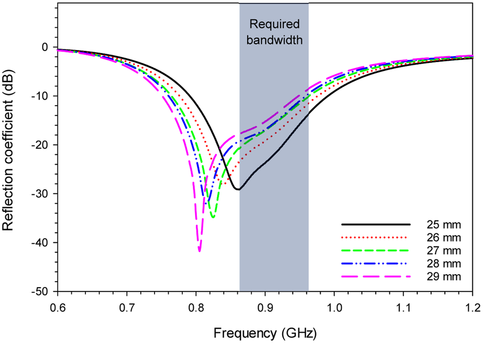
Fig. 16. Reflection coefficient of the PIFA element with a variation of the element's width.

Fig. 17. Total gain of the antenna with a variation of the radiator element's width.

Fig. 18. Reflection coefficient of the PIFA element with a variation of the element's length.

Fig. 19. Total gain of the antenna with a variation of the radiator element's length.
The next parameter study is related to the distance of the PIFA element above the circuit board of the feed network. The PIFA element's width and length were fixed to 25 and 65 mm, respectively. If the distance is small, the antenna is low profile. However, it is shown in Fig. 20 that the impedance matching is degraded as the PIFA element is located near to the PCB of the feed network. Considering the gain flatness over the bandwidth, the optimal height of the element above the feed network is 10 mm as depicted in Fig. 21 with an excellent impedance matching shown in Fig. 20.

Fig. 20. Reflection coefficient of the PIFA element with a variation of the element's height above the feed network's PCB.

Fig. 21. Total gain of the antenna with a variation of the element's height above the feed network's PCB.
Another important feature of the PIFA element is the shorting pin or plate which provides degrees of freedom for the optimization of matching over the bandwidth. Figures 22 and 23 show the effects of the shorting plate's width on the input reflection coefficient and the total gain of the antenna, respectively. It is obvious that the width of the shorting plate does not have a significant effect on the antenna gain. However, the optimal width of 8 mm provides the best matching over the bandwidth of interest. The impedance matching depends strongly on the distance between the feeding element and the shorting plate of the PIFA radiator as shown in Fig. 24. The resonant frequency is increased as the distance between the feed and the shorting plate is increased. The optimal distance is 15 mm regarding the matching of each PIFA element and the total antenna gain as depicted in Fig. 25. Compared to others, this parameter is the most sensitive one regarding the effect on impedance matching and the antenna gain.

Fig. 22. The effect of the shorting plate's width on the reflection coefficient of the PIFA element.

Fig. 23. The effect of the shorting plate's width on the total gain of the antenna.

Fig. 24. Effect of the distance between the feed and shorting plate of the PIFA radiator on the input reflection coefficient.

Fig. 25. The effect of the distance between the feed and shorting plate of the PIFA radiator on the antenna's total gain.
Conclusion
In this paper, a compact wideband circularly polarized directional quadrifilar antenna for UHF RFID readers has been presented. The proposed design is based on PIFA radiators constructed using different parts cut out from an FR-4 PCB. The feed network is a two-stage Wilkinson power divider with delay lines required for the phase shifts to realize the circular polarization. Simulation and measurement results showed that the proposed design could achieve a reflection coefficient <−15 dB over the global UHF RFID frequency band from 860 to 960 MHz. The maximum antenna gain is 3.75 dBic with 1 dB gain variation over the required bandwidth. The AR <−1 dB was realized over the UHF RFID global band. Simulation and measurement results show a good agreement. With a good combination of impedance and AR bandwidth, gain, gain flatness, directional pattern, and simple fabrication, the proposed antenna is a good candidate for UHF RFID applications. The size of the proposed antenna is slightly larger than the one from a previous work with a comparable gain. However, the bandwidth and the gain flatness over the bandwidth are greater. Compared to a conventional directional UHF RFID reader antenna with a 250 × 250 mm2 reflector, our antenna is still considered compact with an area reduction of 77%.
Acknowledgement
This work has been supported by King Mongkut's University of Technology North Bangkok, Contract no. KMUTNBGOV-59-45 and the Thailand Research Fund under the TRF Senior Research Scholar Program with the contract number RTA6080008.
 Chawanat Lerkbangplad is currently completing his Master's degree at the Sirindhorn International Thai-German Graduate School of Engineering (TGGS), King Mongkut's University of Technology North Bangkok (KMUTNB). His master studies were financially supported by the Research and Researchers for Industries (RRi) Master Scholarship awarded by the Thailand Research Fund with partial contribution from Strato Technologies, Ltd. His research interests include design, fabrication, and measurement of UHF RFID reader's antenna for smart warehouse management.
 Alongkorn Namahoot received his B. Eng. degree in Electrical Engineering from KMUTNB, Bangkok, Thailand in 1996, Dipl.-Ing. degree in Electrical Engineering from the University of Kassel, Germany in 2002, and Ph.D. degree from TGGS, KMUTNB in 2019. He joined the Department of Electrical Engineering, KMUTNB in 1996. From 2006 to 2013, he worked full-time in RFID and electronic circuit manufacturing industries. During his Ph.D. study, he worked part-time in RFID reader design and ecosystem platform development from 2014 to 2018. Currently, he is working as a consultant in the RF and microwave electronics for manufacturing industries in Thailand. His research interests include passive and active microwave circuits, antennas, and RF techniques.
 Prayoot Akkaraekthalin received the B.Eng. and M.Eng. degrees in Electrical Engineering from KMUTNB, Bangkok, Thailand, in 1986 and 1990, respectively, and the Ph.D. degree from the University of Delaware, Newark, USA, in 1998. From 1986 to 1988, he worked as an R&D engineer at the Microtek Company, Thailand. In 1988, he joined the Department of Electrical Engineering, KMUTNB. His current research interests include RF/microwave circuits, wideband and multiband antennas, telecommunications, and sensor systems. Professor Prayoot is the author and co-author for over 60 international journals, over 200 conference papers, and four books/book chapters. He was the editor-in-chief for the ECTI Transactions between 2011 and 2013. He is a member of IEEE, IEICE Japan, ECTI, and EEAAT Associations, Thailand. He was the chairman for the IEEE MTT/AP/ED Thailand Joint Chapter from 2007 to 2010 and the vice president and the president for ECTI Association, Thailand from 2012 to 2013 and from 2014 to 2015, respectively. He is now the head of the Senior Research Scholar Project under the grant from Thailand Research Fund (from 2015 to 2020).
 Suramate Chalermwisutkul received his Dipl.-Ing. and Dr.-Ing. degrees in Electrical Engineering from RWTH Aachen University, Germany in 2001 and 2007, respectively. In 2007, he joined The Sirindhorn International Thai-German Graduate School of Engineering (TGGS), KMUTNB as a lecturer/researcher. He has established the RF and Microwave Laboratory at TGGS where he has been holding the position of lab head from the start. Dr. Chalermwisutkul was the communication subsystem manager of the KNACKSAT project in which the first Thai-made satellite was developed and launched to the orbit via SpaceX Falcon 9 rocket, SSO-A mission in 2018. He was also a visiting lecturer at RWTH Aachen University, Germany where he taught a seminar course in electromagnetic sensors for multidisciplinary applications. His research interests include RF systems for Cubesats, smart antennas, reconfigurable RF systems, and EMsensors.


