


NOTATION
Latin
- a
-
angle of incidence (degrees)
- c
-
chord in untapered part of the blade (m)
- k
-
turbulent kinetic energy (Joules)
- l
-
characteristic scale of the flow (main chord at this study) (m)
- v
-
mean velocity of the blade section relative to the fluid (m/s)
- a sound
-
speed of sound (m/s)
- c P
-
pressure coefficient
- C T
-
thrust coefficient, C T = T/(0.5ρπR 2 V 2 tip)
- C Q
-
torque coefficient, C Q = Q/(0.5ρπR 3 V 2 tip)
- E
-
total internal energy per unit mass
- M
-
Mach number (v/a sound)
- N b
-
number of blades
- P i
-
ideal induced rotor power
- P
-
actual rotor power
- R
-
aspect ratio of the blade
- V(t)
-
time dependent control volume
- Re
-
Reynolds number (vl/ν)
- FM
-
figure of merit, FM = P i/P
- BVI
-
blade vortex interaction
- MRB
-
main rotor blade
- CFD
-
computational fluid dynamics
- CVT
-
constant volume tetrahedral
- PIV
-
particle image velocimetry
- SAM
-
spring analogy method
- TFI
-
transfinite interpolation
-
 $\vec{R}_{\mathrm{i,j,k}}$
-
flux residuals at cell (i, j, k)
-
$\vec{w}$
-
vector of conserved variables
-
$\vec{F} a_{\mathrm{i}}$
-
inviscid fluxes
-
$\vec{F} a_{\mathrm{v}}$
-
viscous fluxes
-
$\vec{n} a_{\mathrm{i}}$
-
normal vector of the ith face of a cell
-
$\vec{S}$
-
source term


Subscripts
- ∞
-
free-stream value
- tip
-
tip value
- tpp
-
tip path plane
- nfp
-
no feathering plane
Greek
- α
-
lift slope (rad−1)
- β or β0
-
flapping angle (degrees)
- γ
-
rotor blade lock number, (ϕαcR 4/Ib )
- θ or θ0
-
collective angle at 75%R (degrees)
- λ
-
inflow factor
- ν
-
kinematic viscosity, (μv/ρ,
$\text{m}^2/\text{s}$
) - μ
-
advance ratio
- μv
-
dynamic viscosity (kg/ms)
- ρ
-
density (kg/m3)
- σ
-
rotor solidity, (N b cR/πR 2)
- ω
-
specific dissipation (m2/s3)
-
$\vec{\omega }$
-
rotor rotational speed


1.0 INTRODUCTION
Losses due to flow separation are detrimental to rotor performance and normally occur at the retreating side of the rotor disk where the blade is required to operate at higher angles of attack to balance the rotor disk loads. The retreating blade stall results in highly unsteady flow and introduces vibration. Thus, controlling the flow separation is essential. Gurney flaps are capable of providing extra lift at pitch angles below the stall. The purpose of the study is to investigate the possibility of implementing an active Gurney flap on a rotor blade for controlling the retreating blade stall without altering the dynamics of the helicopter.
1.1 Gurney flaps
The use of Gurney flaps for lift enhancement is well established in the aerospace community and several research works e.g. by Wang et al(Reference Wang, Li and Choi1) document the advantages and disadvantages of these devices. The Gurney flap was introduced by Dan Gurney and its aerodynamics was first studied by Liebeck(Reference Liebeck2). This has been followed by numerous experimental studies by Jeffrey and Zghang(Reference Jeffrey and Zghang3), Trooling et al(Reference Troolin, Longmire and Lai4), and Lee and Su(Reference Lee and Su5). Tang and Dowell (Reference Tang and Dowell6) compared the loading of an NACA0012 wing section with both static and oscillating trailing-edge Gurney flaps using an incompressible Navier-Stokes code against experiments conducted in a wind tunnel by them. Due to the scarcity of experimental data with dynamically deployed Gurney flaps, Chow and Van Dam(Reference Chow and Van Dam7), Baker et al(Reference Baker, Standish and Van Dam8) and Kinzel et al(Reference Kinzel, Maughmer and Duque9) have utilised this set of data in their computational studies.
The Gurney flap is a short flat plate placed at the trailing edge, perpendicular to the chord-line on the pressure side of the aerofoil and works by providing a stagnation area near the trailing edge resulting in an increase of lift. It increases the zero lift angle and keeps the lift slope constant so there is a decrease in the stall angle. The pitching moment coefficient is also increased (i.e. more nose down) as presented by Gai and Palfrey(Reference Gai and Palfrey10), and unless the Gurney is sized carefully, substantial drag penalties may also occur. Based on the review of flow control mechanisms by Yeo(Reference Yeo11), Gurney flaps are generally less than 3% of the wing chord. Previous studies by Jeffrey et al(Reference Jeffrey, Zhang and Hurst12) and Maughmer and Bramesfeld(Reference Maughmer and Bramesfeld13) have concluded that the optimal height for a Gurney flap should be close to the boundary-layer thickness on the pressure side of the aerofoil. If the Gurney flap height is smaller than the boundary-layer thickness, then its influence is significantly decreased, while increasing the size of the flap leads to a drag penalty.
Most of the studies found in the literature are dealing with commonly used aerofoils in rotorcraft applications and try to derive conclusions concerning the potential effect of the Gurney flap on rotor blades according to 2D calculations. Min et al(Reference Min, Sankar, Rajmohan and Prasad14) studied the effects of Gurney flaps on the blade root loads and hub vibratory loads. In their study, a Gurney flap was deployed over the entire span of the BO-105 rotor in forward flight with three different deployment schedules. A carefully chosen azimuthal deployment schedule of the Gurney flap was found to reduce the peak-to-peak variations in hub loads. The 4-per-revolution normal force at the hub was compared with the loads for a higher harmonic controlled rotor and the baseline rotor. The simulations showed that the Gurney flap deployment reduced the 4-per-rev normal force vibration by 80%. For the same rotor in descending flight, a Gurney set at 30 degrees angle relative to the mean chord resulted in a 40% decrease of the vertical descend rate. However, the Gurney flap resulted in local nose-down pitching moment, which indicates that additional fluid-structure coupling analyses for aeroelastic deformation is required.
Active Gurney flaps were also studied by Padthe et al (Reference Padthe, Liu and Friedmann15) to determine their effectiveness in reducing noise and vibration in rotorcraft, as well as improving rotor performance. Active control studies employing microflaps were conducted on a hingeless rotor configuration resembling the MBB BO-105, and various span-wise configurations of the flaps, including a single, a dual, and a segmented five-flap configuration were evaluated. Results indicate that the Gurney flap is capable of substantial reductions in Blade Vortex Interaction (BVI) noise ranging from 3dB to 6dB. Vibration reduction ranging from 70% to 90% was also demonstrated. Vibration and noise reduction was also examined at the same time, and was found that reduction in one was linked to an increase on the other. Finally, the Gurney flap appeared to be more effective in reducing the BVI noise at both advancing and retreating sides while the plain flap was more effective in reducing the vibrations.
The effectiveness of a single active Gurney flap in reducing vibration of a UH-60A Blackhawk helicopter in high-speed flight (μ = 0.35) was studied by Bae and Gandhi (Reference Bae and Gandhi16) based on a 2D Navier-Stokes CFD code. An elastic blade was considered and the Gurney flap was extending from 70%R to 80%R and was deployed to an amplitude of 0.5% of the chord. The Gurney flap actuation was most influential in reducing the vertical vibratory hub force. The most effective actuation input was 4/rev and it led to 80% reduction.
Comparing the above studies (Reference Min, Sankar, Rajmohan and Prasad14-Reference Bae and Gandhi16) to the ones conducted by Milgram et al(Reference Milgram, Chopra and Straub17) and Viswamurthy and Ganguli(Reference Viswamurthy and Ganguli18), it seems that a Gurney flap can have a similar effect on the vibratory loads of the rotor hub like a conventional trailing-edge flap. Such a flap is used on a soft hingeless rotor(Reference Viswamurthy and Ganguli18), leading to a 72% reduction of the vibratory loads. However, the advantage of using a Gurney flap compared to a trailing-edge flap may be on the amount of energy required for the actuation and the ease of the implementation of the Gurney flap.
A further computational study (Reference Yeo19) tried to assess active control mechanisms for rotor performance enhancement. A four-bladed rotor was considered at medium (80Kn) and high (150Kn) speed forward flight cases and the Gurney flap was assumed to be either completely deployed or retracted. A significant increase in thrust for a given power was found when the Gurney was extended from 60%R up to 100%R and activated at the retreating side, which agrees with the outcome of the study by Cheng and Celi(Reference Cheng and Celi20), who defined the optimum 2-per-revolution inputs in order to improve the rotor performance by either increasing the thrust of the rotor or decreasing the torque requirement. However, the positive effect of the Gurney was observed at medium flight speeds, while at high speed, the performance improvement diminished.
Gagliardi and Barakos(Reference Gagliardi and Barakos21) studied a low twist hovering rotor and the effects of trailing-edge flaps on its performance. A flap located inboard resulted in hover performance similar to a blade of 6º more twist. At the same time, a reduction of the trim angles was observed. A flap located outboard did not improve the performance of the rotor, although by carefully optimising its configuration, similar trim benefits as for the inboard flap were achieved.
The majority of the previous studies are computational and there is a need for experimental investigations of Gurney flaps on rotors. There is, however, an experimental and computational study of the aeromechanics of a Sikorsky demonstration rotor(Reference Lorber, Hein, Wong and Wake22) that examined the effect of an active flap. The report points out that the Gurney flap may have similar effects to a conventional flap. However, because of its small size, the Gurney has the potential for high-bandwidth active control with low actuation power requirements and minimal impact to the blade structure when compared to conventional control surfaces.
To conclude, few complete studies concerning Gurney flap implementation on helicopter rotors were found in the literature. All of them investigated the effect of Gurneys on BVI and/or vibration reduction in forward flight, while Pastrikakis et al (Reference Pastrikakis, Steijl and Barakos23) demonstrated the potential effect of Gurney flaps on a hovering rotor. Although there is strong indication from 2D calculations of potential performance enhancement, the question still remains whether there is a practical forward flight benefit to be achieved. In this work, an active Gurney flap is studied on the main rotor blade of the W3 Sokol helicopter. The enhancement of the performance is investigated by coupling fluid and structure calculations, taking into account the structural properties of the Main Rotor Blade (MRB). The method used for the CFD-CSD coupling was presented in detail in the previous studies of aeroelastic rotors(Reference Dehaeze and Barakos24-Reference Dehaeze and Barakos26). To the authors’ knowledge, this is the first effort to investigate the potential effect of a Gurney flap on the overall envelope of a helicopter, along with the flap’s effect on the dynamics of a full helicopter model.
2.0 NUMERICAL METHODS
2.1 HMB2 flow solver
The HMB2 CFD solver (Reference Steijl, Barakos and Badcock27-Reference Barakos, Steijl, Badcock and Brocklehurst29) was employed for this work. HMB2 solves the Navier-Stokes equations in integral form using the arbitrary Lagrangian Eulerian formulation for time-dependent domains with moving boundaries:
 $$\begin{equation}
\frac{\mathrm{d}}{\mathrm{d} t}\int _{V(t)}\vec{w}dV + \int _{\partial {V(t)}} (\vec{F}_{\mathrm{i}}(\vec{w}) - \vec{F}_{\mathrm{v}}(\vec{w}))\vec{n}dS = \vec{S}{.}
\end{equation}$$
$$\begin{equation}
\frac{\mathrm{d}}{\mathrm{d} t}\int _{V(t)}\vec{w}dV + \int _{\partial {V(t)}} (\vec{F}_{\mathrm{i}}(\vec{w}) - \vec{F}_{\mathrm{v}}(\vec{w}))\vec{n}dS = \vec{S}{.}
\end{equation}$$
The above equation forms a system of conservation laws for any time-dependent control volume V(t) with boundary ∂V(t) and outward unit normal
 $\vec{n}$
. The vector of conserved variables is denoted by
$\vec{n}$
. The vector of conserved variables is denoted by
 $\vec{w} = [\rho , \rho u, \rho v, \rho w, \rho E]^T$
, where ρ is the density, u, v, w are the Cartesian velocity components and E is the total internal energy per unit mass.
$\vec{w} = [\rho , \rho u, \rho v, \rho w, \rho E]^T$
, where ρ is the density, u, v, w are the Cartesian velocity components and E is the total internal energy per unit mass.
 $\vec{F}_{\mathrm{i}}$
and
$\vec{F}_{\mathrm{i}}$
and
 $\vec{F}_{\mathrm{v}}$
are the inviscid and viscous fluxes, respectively. For hovering rotors, the grid is fixed, and a source term,
$\vec{F}_{\mathrm{v}}$
are the inviscid and viscous fluxes, respectively. For hovering rotors, the grid is fixed, and a source term,
 $\vec{S} = [0, -\rho \vec{\omega } \times \vec{u}_{\mathrm{h}}, 0]^T$
, is added to compensate for the inertial effects of the rotation.
$\vec{S} = [0, -\rho \vec{\omega } \times \vec{u}_{\mathrm{h}}, 0]^T$
, is added to compensate for the inertial effects of the rotation.
 $\vec{u}_{\mathrm{h}}$
is the local velocity field in the rotor-fixed frame of reference, added as mesh velocity.
$\vec{u}_{\mathrm{h}}$
is the local velocity field in the rotor-fixed frame of reference, added as mesh velocity.
Equation (1) is discretised using a cell-centred finite volume approach on structured multiblock grids. The spatial discretisation leads to a set of equations in time:
 $$\begin{equation}
\frac{\partial }{\partial t}(\vec{w}_{\mathrm{i,j,k}}V_{\mathrm{i,j,k}}) = - \vec{R}_{\mathrm{i,j,k}}(\vec{w}_{\mathrm{i,j,k}}) \text{,}
\end{equation}$$
$$\begin{equation}
\frac{\partial }{\partial t}(\vec{w}_{\mathrm{i,j,k}}V_{\mathrm{i,j,k}}) = - \vec{R}_{\mathrm{i,j,k}}(\vec{w}_{\mathrm{i,j,k}}) \text{,}
\end{equation}$$
where
 $\vec{w}$
and
$\vec{w}$
and
 $\vec{R}$
are the vectors of cell variables and residuals, respectively. Here, i,j,k are the cell indices in each of the grid blocks, and V
i, j, k is the cell volume. The convective terms are discretised using Osher’s upwind scheme (Reference Osher and Chakravarthy30), MUSCL variable interpolation is used to provide high order accuracy and the Van Albada limiter (Reference Van Albada, Van Leer and Roberts31) is employed to prevent spurious oscillations near steep gradients. Boundary conditions are set using ghost cells on the exterior of the computational domain. For viscous flow simulations, ghost values are extrapolated at solid boundaries ensuring that the velocity takes on the solid wall velocity. Implicit time integration is employed, and the resulting linear system of equations is solved using a pre-conditioned Generalised Conjugate Gradient method. For unsteady simulations, an implicit dual-time stepping method is used, based on the pseudo-time integration approach by Jameson(Reference Jameson32). The HMB2 method has been validated for a range of rotorcraft applications and has demonstrated good accuracy and efficiency for very demanding flows. Examples of work with HMB2 can be found in Refs 28, 28, and 33. Several rotor-trimming methods are available in HMB2 along with a blade-actuation algorithm that allows for the near-blade grid quality to be maintained on deforming meshes(Reference Steijl, Barakos and Badcock27).
$\vec{R}$
are the vectors of cell variables and residuals, respectively. Here, i,j,k are the cell indices in each of the grid blocks, and V
i, j, k is the cell volume. The convective terms are discretised using Osher’s upwind scheme (Reference Osher and Chakravarthy30), MUSCL variable interpolation is used to provide high order accuracy and the Van Albada limiter (Reference Van Albada, Van Leer and Roberts31) is employed to prevent spurious oscillations near steep gradients. Boundary conditions are set using ghost cells on the exterior of the computational domain. For viscous flow simulations, ghost values are extrapolated at solid boundaries ensuring that the velocity takes on the solid wall velocity. Implicit time integration is employed, and the resulting linear system of equations is solved using a pre-conditioned Generalised Conjugate Gradient method. For unsteady simulations, an implicit dual-time stepping method is used, based on the pseudo-time integration approach by Jameson(Reference Jameson32). The HMB2 method has been validated for a range of rotorcraft applications and has demonstrated good accuracy and efficiency for very demanding flows. Examples of work with HMB2 can be found in Refs 28, 28, and 33. Several rotor-trimming methods are available in HMB2 along with a blade-actuation algorithm that allows for the near-blade grid quality to be maintained on deforming meshes(Reference Steijl, Barakos and Badcock27).
The HMB2 solver has a library of turbulence closures, including several one- and two- equation turbulence models and even non-Boussinesq versions of the k − ω model that is used for this work. Turbulence simulation is also possible using either the Large-Eddy or the Detached-Eddy approach. The solver was designed with parallel execution in mind and the MPI library along with a load-balancing algorithm are used to this end. For multi-block grid generation, the ICEM-CFD Hexa commercial meshing tool is used and CFD rotor grids with 10–100 million points and thousands of blocks are routinely used.
For forward flying rotors, the HMB2 solves the compressible-flow Reynolds-Averaged Navier-Stokes equations in an inertial frame of reference. The employed finite-volume discretisation accounts for moving and deforming meshes in time-accurate simulations. Consequently, a rotor in forward flight is modelled in a ‘helicopter-fixed frame of reference,’ where the forward flight velocity is introduced through the definition of the ‘free-stream’ conditions. For isolated rotors, as well as, rotor/fuselage or rotor/wind-tunnel cases, the rotor and rotor blade motions are then accounted for using mesh velocities. For rotor/fuselage or rotor/wind-tunnel cases, the relative motion of the rotor and the fixed fuselage or tunnel is accounted for using the sliding-plane approach(Reference Steijl and Barakos28).
2.2 Modelling Gurney flaps
For the purposes of this study, the effect of the Gurney flap on W3-Sokol MRB is modelled by flagging any block face within the computational mesh occupied by the flap with a solid, no-slip boundary condition. This method is implemented in the HMB2 solver and is proved to be simple and effective(Reference Woodgate and Barakos34,Reference Woodgate, Pastrikakis and Barakos35) . To be able to obtain the loads on the Gurney flap alone and to be able to find its moment about a different point – for example, the Gurney’s hinge – HMB2 requires some additional information. Firstly, a special boundary condition tag must be used for the Gurney flap to be identified. Secondly, additional input files must be used to inform HMB2 that computations are to be performed with a Gurney flap. The advantage of this method is that no additional effort is needed in terms of mesh generation. On the other hand, the Gurney is assumed to have no thickness. In case of an actuated Gurney flap, a method with overset grids would be required. Otherwise, the deformation of the mesh near the flap would alter the quality of the mesh to an acceptable level. Modelling the effect of the flap, as stated above, infinitely thin Gurney flap allows the mesh quality to remain the same, as the mesh does not deform with the actuation of the flap.
2.3 Trimming method
The trimmer used for this study is based on the blade element theory. Approximate equations are used from aeromechanics to estimate the gradient of the thrust and the torque, with respect to the control angles. These angles are then used to trim the rotors, as explained by Steijl et al(Reference Steijl, Barakos and Badcock27). The trimming method consists of an initial trim-state computation and a number of subsequent re-trimming steps. The initial trim state can be obtained either off-line or within the CFD solver. During re-trimming, the collective pitch is updated via a Newton-Raphson process, where the simple aerodynamic model is only used to compute the derivatives of the loads. As a result, upon convergence, the trim state is independent of the approximate aerodynamics. For simulations of forward-flying rotors, re-trimming is carried out after completion of one rotor revolution using revolution-averaged integrated loads from the CFD solution. The trimming method needs a target thrust coefficient c T as input. For this study, the thrust estimate is given based on the flight tests. In addition, models for the fuselage and its drag are necessary in order to compute the total drag, as a function of the advance ratio of the helicopter. From the rotor thrust and total drag, the orientation of the tip-path plane can be obtained, i.e. the forward tilt. For a rotor at straight level conditions, the orientation of the tip-path plane can be obtained from sinθtpp = −D/W, where D and W represent the total drag of the helicopter and its weight.
Assuming a fixed rotor shaft angle θ shaft and known first harmonic flap coefficients β1s and β1c , the thrust and moment coefficients can be expressed as a function of collective and cyclic pitch angles:
 $$\begin{eqnarray*}
C_T = C_T (\theta _0 , \theta _{1c}, \theta _{1s}),\nonumber \\
C_{M,x} = C_{M,x} (\theta _0 , \theta _{1c}, \theta _{1s}),\nonumber \\
C_{M,y} = C_{M,y} (\theta _0 , \theta _{1c}, \theta _{1s}),\nonumber
\end{eqnarray*}$$
$$\begin{eqnarray*}
C_T = C_T (\theta _0 , \theta _{1c}, \theta _{1s}),\nonumber \\
C_{M,x} = C_{M,x} (\theta _0 , \theta _{1c}, \theta _{1s}),\nonumber \\
C_{M,y} = C_{M,y} (\theta _0 , \theta _{1c}, \theta _{1s}),\nonumber
\end{eqnarray*}$$
where C M, x and C M, y are the non-dimensional moments about the x-axis (rotor disk rolling moment) and y-axis (rotor disk pitching moment), respectively. During a re-trim step, the collective and cyclics are updated as:
 $$\begin{eqnarray}
\left( \begin{array}{c}\Delta \theta _0\\
\Delta \theta _{1s}\\
\Delta \theta _{1c} \end{array} \right) = \left( \begin{array}{ccc}\frac{\partial C_T}{\partial \theta _0} &\frac{\partial C_T}{\partial \theta _{1s}} &\frac{\partial C_T}{\partial \theta _{1c}}\\[6pt]
\frac{\partial C_{M,x}}{\partial \theta _0} &\frac{\partial C_{M,x}}{\partial \theta _{1s}} &\frac{\partial C_{M,x}}{\partial \theta _{1c}}\\[6pt]
\frac{\partial C_{M,y}}{\partial \theta _0} &\frac{\partial C_{M,y}}{\partial \theta _{1s}} &\frac{\partial C_{M,y}}{\partial \theta _{1c}} \end{array} \right)^{-1} \left( \begin{array}{c}C_{T, target} - C_T\\
C_{M_x, target} - C_{M_x}\\
C_{M_y, target} - C_{M_y} \end{array} \right)
\end{eqnarray}$$
$$\begin{eqnarray}
\left( \begin{array}{c}\Delta \theta _0\\
\Delta \theta _{1s}\\
\Delta \theta _{1c} \end{array} \right) = \left( \begin{array}{ccc}\frac{\partial C_T}{\partial \theta _0} &\frac{\partial C_T}{\partial \theta _{1s}} &\frac{\partial C_T}{\partial \theta _{1c}}\\[6pt]
\frac{\partial C_{M,x}}{\partial \theta _0} &\frac{\partial C_{M,x}}{\partial \theta _{1s}} &\frac{\partial C_{M,x}}{\partial \theta _{1c}}\\[6pt]
\frac{\partial C_{M,y}}{\partial \theta _0} &\frac{\partial C_{M,y}}{\partial \theta _{1s}} &\frac{\partial C_{M,y}}{\partial \theta _{1c}} \end{array} \right)^{-1} \left( \begin{array}{c}C_{T, target} - C_T\\
C_{M_x, target} - C_{M_x}\\
C_{M_y, target} - C_{M_y} \end{array} \right)
\end{eqnarray}$$
The elements of the sensitivity matrix in Equation (3) are the derivatives of CT, C M, x and C M, y , according to blade-element theory. Assuming a constant inflow factor λ and fixed flapping harmonics, the sensitivity matrix reads:
 $$\begin{eqnarray}
\left(\begin{array}{ccc}\frac{\partial C_T}{\partial \theta _0} &\frac{\partial C_T}{\partial \theta _{1s}} &\frac{\partial C_T}{\partial \theta _{1c}}\\[6pt]
\frac{\partial C_{M,x}}{\partial \theta _0} &\frac{\partial C_{M,x}}{\partial \theta _{1s}} &\frac{\partial C_{M,x}}{\partial \theta _{1c}}\\[6pt]
\frac{\partial C_{M,y}}{\partial \theta _0} &\frac{\partial C_{M,y}}{\partial \theta _{1s}} &\frac{\partial C_{M,y}}{\partial \theta _{1c}} \end{array}\right) = \frac{\sigma a}{4} \left(\begin{array}{c@{\quad}c@{\quad}c}\big (\frac{2}{3} + \mu ^2\big ) &-\mu &0\\[6pt]
\frac{2}{3}\mu &-\frac{1}{4}\big (1 + \frac{3}{2}\mu ^2\big ) &0\\[6pt]
0 &0 &\frac{1}{4}\big (1 + \frac{1}{2}\mu ^2\big ) \end{array}\right)
\end{eqnarray}$$
$$\begin{eqnarray}
\left(\begin{array}{ccc}\frac{\partial C_T}{\partial \theta _0} &\frac{\partial C_T}{\partial \theta _{1s}} &\frac{\partial C_T}{\partial \theta _{1c}}\\[6pt]
\frac{\partial C_{M,x}}{\partial \theta _0} &\frac{\partial C_{M,x}}{\partial \theta _{1s}} &\frac{\partial C_{M,x}}{\partial \theta _{1c}}\\[6pt]
\frac{\partial C_{M,y}}{\partial \theta _0} &\frac{\partial C_{M,y}}{\partial \theta _{1s}} &\frac{\partial C_{M,y}}{\partial \theta _{1c}} \end{array}\right) = \frac{\sigma a}{4} \left(\begin{array}{c@{\quad}c@{\quad}c}\big (\frac{2}{3} + \mu ^2\big ) &-\mu &0\\[6pt]
\frac{2}{3}\mu &-\frac{1}{4}\big (1 + \frac{3}{2}\mu ^2\big ) &0\\[6pt]
0 &0 &\frac{1}{4}\big (1 + \frac{1}{2}\mu ^2\big ) \end{array}\right)
\end{eqnarray}$$
Solving Equation (3) gives:
 $$\begin{eqnarray}
\Delta \theta _0 = \Big [\frac{\partial C_T}{\partial \theta _0}\frac{\partial C_{M,x}}{\partial \theta _{1s}} - \frac{\partial C_T}{\partial \theta _{1s}}\frac{\partial C_{M,x}}{\partial \theta _0}\Big ]^{-1} \Big (\frac{\partial C_{M,x}}{\partial \theta _{1s}}\big (C_{T, target} - C_T\big ) + \frac{\partial C_T}{\partial \theta _{1s}} C_{M_x}\Big ), \nonumber \\
\Delta \theta _{1s} = \Big [\frac{\partial C_T}{\partial \theta _0}\frac{\partial C_{M,x}}{\partial \theta _{1s}} - \frac{\partial C_T}{\partial \theta _{1s}}\frac{\partial C_{M,x}}{\partial \theta _0}\Big ]^{-1} \Big (-\frac{\partial C_{M,x}}{\partial \theta _0}\big (C_{T, target} - C_T\big ) - \frac{\partial C_T}{\partial \theta _0} C_{M_x}\Big ), \\
\Delta \theta _{1c} = -C_{M_x}/\frac{\partial C_{M,y}}{\partial \theta _{1c}}\nonumber
\end{eqnarray}$$
$$\begin{eqnarray}
\Delta \theta _0 = \Big [\frac{\partial C_T}{\partial \theta _0}\frac{\partial C_{M,x}}{\partial \theta _{1s}} - \frac{\partial C_T}{\partial \theta _{1s}}\frac{\partial C_{M,x}}{\partial \theta _0}\Big ]^{-1} \Big (\frac{\partial C_{M,x}}{\partial \theta _{1s}}\big (C_{T, target} - C_T\big ) + \frac{\partial C_T}{\partial \theta _{1s}} C_{M_x}\Big ), \nonumber \\
\Delta \theta _{1s} = \Big [\frac{\partial C_T}{\partial \theta _0}\frac{\partial C_{M,x}}{\partial \theta _{1s}} - \frac{\partial C_T}{\partial \theta _{1s}}\frac{\partial C_{M,x}}{\partial \theta _0}\Big ]^{-1} \Big (-\frac{\partial C_{M,x}}{\partial \theta _0}\big (C_{T, target} - C_T\big ) - \frac{\partial C_T}{\partial \theta _0} C_{M_x}\Big ), \\
\Delta \theta _{1c} = -C_{M_x}/\frac{\partial C_{M,y}}{\partial \theta _{1c}}\nonumber
\end{eqnarray}$$
Similar approaches have been used in Refs 36-38. Yang et al(Reference Yang, Sankar, Smith and Bauchau36) used a lifting-line technique, external to the flow solver, to obtain the derivatives of the rotor performance parameters. An alternative, expensive approach is presented in Refs Reference Van der Ven and Boelens37 and Reference Park and Kwon38, where the flow solver is used to determine the derivatives of the rotor performance parameters by repeating the simulation with slightly different values of the angles θ0, θ1c and θ1c in succession. An accurate estimate of the derivatives requires a converged flow solution for each of these different control settings. Typical trimmed rotor simulations involved up to 35 revolutions of the rotor in total.
2.4 CSD solver and aeroelastic coupling
A modal approach was chosen in order to compute the deformed shape of the blade. The final deformation is then considered as a combination of the eigenvectors of the blade. The mode shapes and frequencies are first computed using the NASTRAN(39) CSD code. The blade structure is represented as a set of beam elements located on the elastic axis of the blade. The non-linear PBEAM elements of NASTRAN(39) were used. For each section, a rigid bar (RBAR element) without any structural properties and rigidly linked to the chord nodes was added in front of the trailing edge and aft of the leading edge in order to assess the displacement of the blade surface. The blade lead-lag stiffness is represented as a linear elastic element. An example of such a model is shown in forward flight computations presented in Section 7.
The mode shapes and frequencies are obtained through NASTRAN by performing a non-linear static calculation (SOL106). The data requested by NASTRAN for a PBEAM beam element are the flapping and chord-wise area moments of inertia and the linear mass. Other properties can be added, introducing the offset between the beam element axis and the blade elastic axis, as well as the radius of gyration that allows coupling between the flap-wise, chord-wise and torsional deformations. These data have to be specified at least at the root of the element, but can also be specified at other locations of the element.
The structural model of a blade usually contains less elements than the blade surface on the fluid mesh. Therefore, the structural solution has to be interpolated on the blade surface. The deformation of the fluid mesh is done in three main steps. Firstly, the constant volume tetrahedron (CVT) method(Reference Goura, Badcock, Woodgate and Richards40) is used to interpolate the deformed shape of the blade surface. Secondly, the block vertices are moved according to the spring analogy method. Finally, the full mesh is regenerated with a trans-finite interpolation (TFI)(Reference Dubuc, Cantariti, Woodgate, Gribben, Badcock and Richards41). The interpolation process is described in detail in Refs 24-26.
For forward flying rotors, the modal approach is used to lower the cost of computing the blade deformations. It expresses the blade deformation as a function of the blade eigenmodes. The blade shape ϕ is then described as a sum of eigenvectors ϕ i representing the blade displacements for each eigenmode multiplied by the coefficient α i :
 $$\begin{equation}
\phi =\phi _0 + \sum _{i=1}^{n_m} \alpha _i \phi _i,
\end{equation}$$
$$\begin{equation}
\phi =\phi _0 + \sum _{i=1}^{n_m} \alpha _i \phi _i,
\end{equation}$$
where ϕ0 is the undeformed eigenvector. The problem is then reduced to solving for the coefficient α i .
In the modal approach, the coefficients can be obtained by solving the following differential equation coupled with the time:
 $$\begin{equation}
\frac{\partial ^2 \alpha _i}{\partial t^2}+2 \zeta _i \omega _i \frac{\partial \alpha _i}{\partial t} + \omega _i^2 \alpha _i = \mathbf {f} \times \phi _i,
\end{equation}$$
$$\begin{equation}
\frac{\partial ^2 \alpha _i}{\partial t^2}+2 \zeta _i \omega _i \frac{\partial \alpha _i}{\partial t} + \omega _i^2 \alpha _i = \mathbf {f} \times \phi _i,
\end{equation}$$
where f are the external forces applied to the blade projected at each structural node, and ζ i is the structural damping coefficient.
3.0 W3-SOKOL
3.1 MRB geometry
The W3-Sokol main rotor consists of four blades made out of fibre-glass. It is a soft blade in torsion that encourages the idea of the implementation of a Gurney flap in order to alter the twist distribution along the radius of the blade. Figure 1 presents the geometry of the original MRB. The radius of the blade is along the x axis and the leading-edge points towards the positive y axis, as the blade is rotating counter-clockwise. Although different sections of five-digit NACA series are used along the radius, the basic section is the NACA23012M, which is created by taking some camber out of the baseline NACA23012. At 0.678R of the blade, there is a trim tab of 0.1c length and 0.07R span, while from 0.75R and up to the blade tip there is a trailing-edge tab of 0.05c. The tip of the blade is rounded, as shown in Fig. 1- III. The MRB has a blunt trailing edge. All these geometrical characteristics increased the complexity of the generated mesh. Adding a fixed Gurney within the multiblock mesh topology increased the number of nodes and required additional computational time to calculate even the hover cases. For this reason, the implementation of an infinitely thin Gurney flap was essential. For hover flight, a Gurney flap of 0.02c height was placed at 0.46R, and had a span of 0.2R, as shown in Fig. 1-I, while for forward flight, the flap was extended inboard by 0.05R. The Gurney flap was flagged using the local mesh around the blade. This allows a flap of infinite thickness, normal to the trailing edge, to be simulated. The process of localising the flap and flagging cells as solid is described by Woodgade and Barakos(Reference Woodgate and Barakos34). The mesh used for the forward flight calculations consists of 27 million nodes. It is a combined C-type topology in the chord-wise plane with 402 nodes along the blade and O-type topology in the span-wise plane with 196 nodes around every section of the blade. In the normal direction of the blade, 64 nodes have been used. The domain is split in the rotor mesh which includes the rotor blade geometry and the hub, and the background mesh. The flow in the interface of those two meshes is interpolated using sliding planes. The whole domain is split in 5,480 blocks and it is presented in Fig. 2.
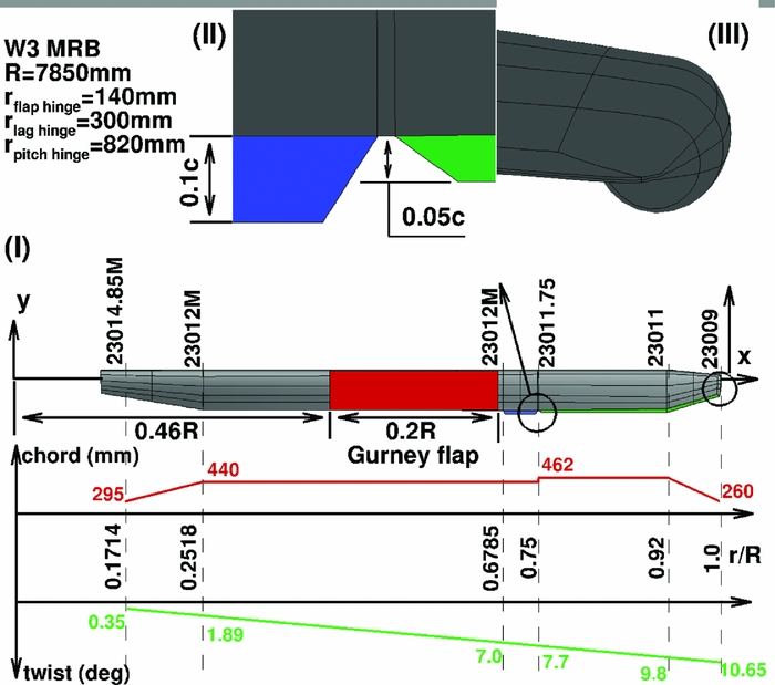
Figure 1. (I) Geometry of W3-Sokol MRB, (II) close view at the trim tab and the trailing-edge tab, (III) close view at the tip.
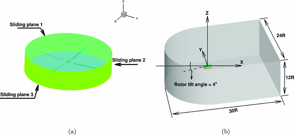
Figure 2. (a) Sliding planes around W3 MR in forward flight, and (b) overview of the computational domain used for the forward flight calculations.
3.2 Hover flight
Earlier work(Reference Pastrikakis, Steijl and Barakos23) demonstrated the potential effect of a Gurney flap on the performance of the W3-Sokol rotor blade in hover. A rigid blade was first considered and the calculations were conducted at several thrust settings. The Gurney flap was extended from 46%R to 66%R and it was located at the trailing edge of the main rotor blade. Four different sizes of Gurney flaps were studied, 2%, 1%, 0.5% and 0.3% of the chord, and the biggest flap proved to be the most effective. In addition, elastic blades were studied with and without the Gurney flap. The results were trimmed at the same thrust values as the rigid blade and indicate an increase of aerodynamic performance when the Gurney flap is used, especially for high thrust cases. Comparative performance calculations have been conducted at six different thrust targets for the rigid clean blade using the k − ω SST turbulence model. The maximum Figure of Merit (FM) of the blade did not improve, but at high thrust settings it was enhanced by 6% over the performance of the clean blade. The effect of the Gurney flap to pitch the nose of the section down was evaluated with aeroelastic calculations and it was found that the extra lift of the Gurney in combination with the extra blade twist resulted in an increased FM, which corresponds to an additional weight of 120kg, as presented in Fig. 3.

Figure 3. (a) Figure of merit, and (b) torque coefficient against normalised thrust coefficient for W3-Sokol blade in hover.
3.3 Forward flight
For the aeroelastic forward flight computations, the mode shapes of the W3-Sokol MRB based on the structural model of Fig. 4 were given to the solver as an initial shape of the elastic blade. Modes up to the first torsional mode were used. These mode shapes are presented in Table 1, and they are mixed flapping, in-plane, and torsional deformations, which made it hard to characterise them. Figure 5 presents the shape of the rigid and the elastic blade shapes at the back of the disk. The tip of the elastic blade is pitching down by 10º compared to the rigid, while the blade is flapping more by almost 2º, while the lag angle is almost 3º. The elastic rotor was trimmed at CT
= 0.0117 (
 $\hbox{6,400} \,\text{kg}$
) for both clean and Gurney cases in order to evaluate the effect of the flap, while the disk pitching and rolling moments were driven to zero. The advance ratio of the rotorcraft was μ = 0.339. Figure 6 presents the trimming history of the computations. For the case where the Gurney was actuated, the torque requirement of the rotor was decreased by 3.3% which corresponds to
$\hbox{6,400} \,\text{kg}$
) for both clean and Gurney cases in order to evaluate the effect of the flap, while the disk pitching and rolling moments were driven to zero. The advance ratio of the rotorcraft was μ = 0.339. Figure 6 presents the trimming history of the computations. For the case where the Gurney was actuated, the torque requirement of the rotor was decreased by 3.3% which corresponds to
 $40\,\text{KW}$
. This reduction is occurred at the retreating side of the disk because of the stall decrease. Figure 7 presents the streamlines on the separation region of the blade at Ψ = 270°, along with the effect of the Gurney flap. The blade shown in Fig. 7(b) is pitched down and the flow is less separated compared to the clean case. In fact, the observed benefits are due to the aerodynamic enhancement of the blade which allows the rotor to operate at a lower collective, as well as allowing the aeroelastic re-shaping of the blade due to the pitching moments induced by the flap.
$40\,\text{KW}$
. This reduction is occurred at the retreating side of the disk because of the stall decrease. Figure 7 presents the streamlines on the separation region of the blade at Ψ = 270°, along with the effect of the Gurney flap. The blade shown in Fig. 7(b) is pitched down and the flow is less separated compared to the clean case. In fact, the observed benefits are due to the aerodynamic enhancement of the blade which allows the rotor to operate at a lower collective, as well as allowing the aeroelastic re-shaping of the blade due to the pitching moments induced by the flap.
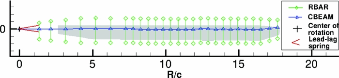
Figure 4. Structural model of W3-Sokol MRB.
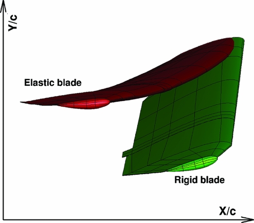
Figure 5. Visualisation of the rigid and elastic W3 MRB in forward flight at Ψ = 0 o . Case conditions are presented in Table 2.

Figure 6. Trimming history of (a) thrust, (b) torque, (c) rotor disk pitching moment and (d) rotor disk rolling moment of the elastic W3 Sokol MR in forward flight. Flight conditions are presented in Table 2.

Figure 7. Visualisation of the separated flow for (a) the clean blade and (b) the blade with an active gurney of 0.02c at Ψ = 270° of the W3 Sokol MR in forward flight. Case conditions are presented in Table 2.
Table 1 Identified modes for W3 MRB rotating at 268.485 rpm
3.3.1 Gurney flap effect along the flight envelope
Since more data was available from flights for the W3 Sokol, CFD calculations were performed at lower advance ratio and thrust requirements. The reason was to identify the effect of the Gurney flap along the full flight envelope of the W3 Sokol helicopter for the same actuation schedule of the flap. Figure 13 presents the trimming history of the elastic rotor with and without the Gurney flap for μ = 0.11 and W = 6, 000kg, as well as a comparison against the high-speed and high-weight forward flight cases. It has to be noted that for a complete aeroelastic trimmed computation, it takes about 250,000 CPU-hours to finish. The most useful outcome of this study is the power reduction gain of the rotor because of the active Gurney flap. Figure 9 shows the effect of the flap from hover to high-speed forward flight. For this weight of the W3-Sokol, the Gurney shows no benefit in hover, although it becomes very beneficial in higher thrust requirement, as presented in the hover section. During forward flight, the flap becomes beneficial close to μ = 0.11. At high-speed and high-weight cases, the potential effect of the Gurney on the retreating blade stall alleviation enhances the aerodynamic performance of the rotor and reduces the power requirements significantly. However, Fig. 9 clearly shows that a Gurney should be deployed during hover only for high-thrust requirements, while it should remain retracted at low forward flight speed.
4.0 GURNEY EFFECT ON STRUCTURAL PROPERTIES OF THE BLADE
The effect of different tip designs on the aeroelastic properties of a blade was studied using the S-76 blade. The idea is to compare that effect with the effect of the Gurney flap on the W3-Sokol blade. Four different tip designs are used– a rectangular, a tapered, a swept and a tapered-swept, as presented in Fig. 8. What changes between the four designs is the mass distribution, the torsional inertia of the tip segment and the location of the elastic axis and centre of gravity at the tip. The comparison of the modes up to 125 Hz between the baseline case and the tapered-swept tip design is presented in Fig. 10. It is to be noted that the different designs did not alter the characterisation of the modes and the frequencies were shifted by less than 1%, compared to the baseline tip design. This outcome shows that even such differences in the design, which lead to significant changes on the aerodynamic behaviour of the blade, will not affect significantly the aeroelastic response of the blade. Figure 11 presents the properties used in NASTRAN for three different blades, the S-76, the W3-Sokol, and the UH60A blade, to get an insight of the different parameters used in the models. Finally, the effect of the additional mass of the Gurney flap actuation mechanism on the aeroelastic response of the blade was tested by distributing an additional 10% of the total mass of the blade at the sections where the Gurney flap was located. Figure 12 presents the spoke diagram of the clean blade and a comparison against the fully instrumented blade is given in Table 2. Again, for the added mass, the mode shape characterisation was not altered by the Gurney flap mechanism, while the frequencies of the given modes were decreased up to 1.6%. As a result it seems that the uncertainty due to the Gurney flap is of the same order of magnitude with the one introduced due to the different tip shape designs.
Figure 8. Different tip shapes of S-76 blade (Reference Garcia and Barakos48).
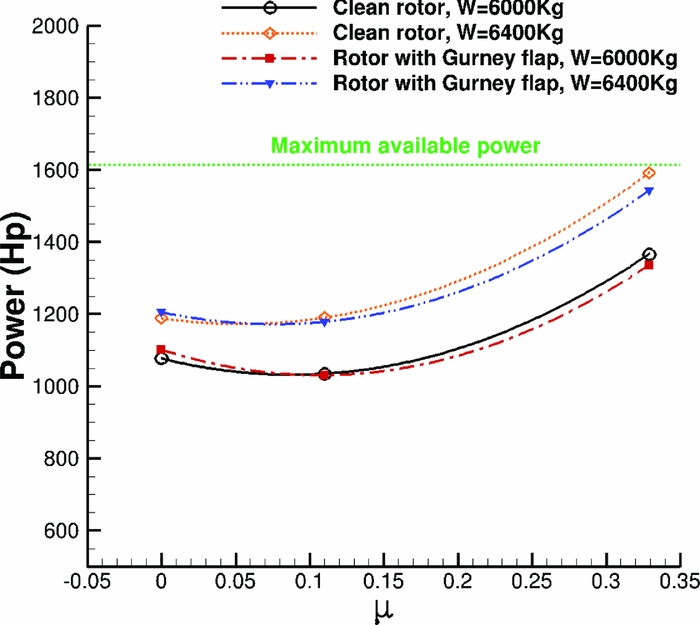
Figure 9. Power requirements for W3 Sokol MRB along flight envelope with and without Gurney flap.
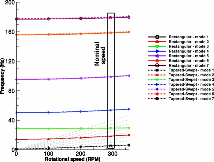
Figure 10. Spoke diagram for S-76 blade, comparison between rectangular and tapered-swept tip design.
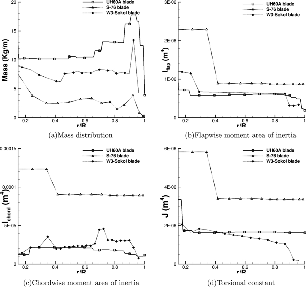
Figure 11. Structural properties of different blades used for static computations.
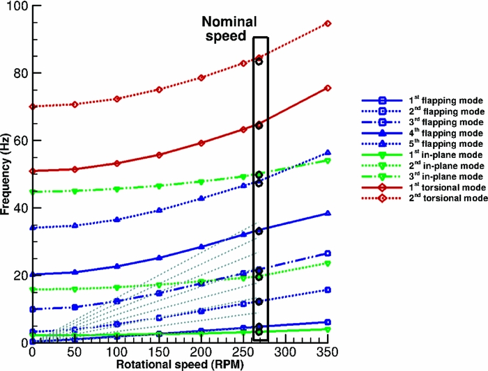
Figure 12. Spoke diagram for W3-Sokol blade. Circles are used for blade with Gurney flap.

Figure 13. Trimming history of (a) thrust, (b) torque of the elastic W3 Sokol MR in forward flight. Comparison between high speed and low speed case.
Table 2 Mode shapes frequencies for clean blade and blade with fixed flap in hover, ω = 268.48 RPM
5.0 CLOSED LOOP CONTROL
For the forward flight of the W3-Sokol rotor, CFD computations for the clean rotor were used to derive the flap actuation schedule. However, in actual helicopter flight, there must be a controller that will actuate the Gurney flap based on some observations of flight parameters. The idea is to detect the pressure divergence at the leading edge of the blade section that is indicative of stall, and if that exceeds a threshold then the flap will be actuated. Moreover, the 1/Rev actuation of the Gurney that was used in the previous chapter could introduce limitations on the handling and trimming of the helicopter. This topic was addressed by building a generic rotorcraft and performing several linear/non-linear analyses to study its response to different control inputs.
5.1 2D closed loop control
An NACA23012M aerofoil section was set to pitching-translating (dMdt) motion(Reference Woodgate and Barakos42). The aim was to investigate retreating blade stall to identify divergence of the cP peaks at the suction side of a blade section that could be used for the closed loop actuation of the Gurney. During the dMdt computations, the pressure coefficient at the leading edge increased gradually at first and then the gradient became steeper before it reduced markedly, and it even reduced when the aerofoil stalled. The cP threshold, when the flow was about to separate, was estimated close to − 3.5. Figure 14 compares the maximum pressure coefficient that was observed at the clean aerofoil and at the aerofoil with the active Gurney during the dMdt computations. For that particular actuation, two revolutions are needed for the flow to converge before the cP is extracted to compute the Gurney schedule. Then, the aerofoil must be trimmed at the clean mean CL and extract the new pressure coefficient to adjust the Gurney flap deployment. After a total number of eight revolutions, the lift is trimmed and the aerodynamic loads are presented in Figs 15–17. Figure 18 presents the pitching motion change of the aerofoil during the Gurney actuation and the trimming of the aerofoil. The high harmonics that appear could be justified by the fact that during the actuation, the Gurney flap sheds small vortices behind. Figures 19 and 20 show the streamlines near the trailing edge for different azimuth steps and how the separated flow is reattached after the actuation of the Gurney. It should also be mentioned that the cP limit that defines the onset of the stall is only valid when the flow is fully attached. That means that when the flow is separated and it reattaches again, then this pressure threshold is significantly higher. In that case cP = 5 is the indicative value for the Gurney retraction, as the flow seems to be completely reattached on the aerofoil after the actuation of the flap. This can be seen in Fig. 21, where the flow is visualised at different steps.
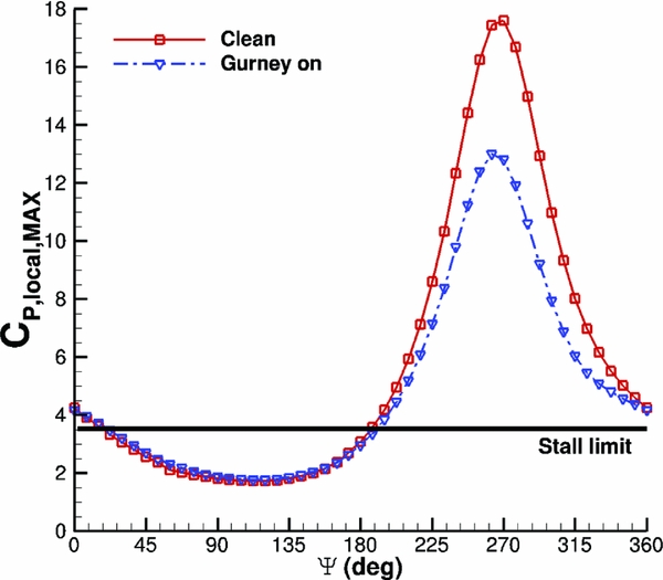
Figure 14. Pitching translating aerofoil - c P, MAX criterion.
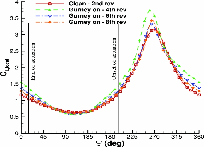
Figure 15. Pitching translating aerofoil - CL loads during control implementation.
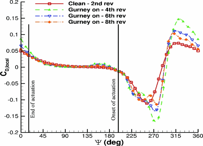
Figure 16. Pitching translating aerofoil - CD loads during control implementation.
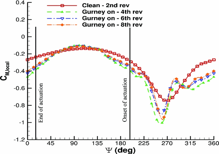
Figure 17. Pitching translating aerofoil - CM loads during control implementation.
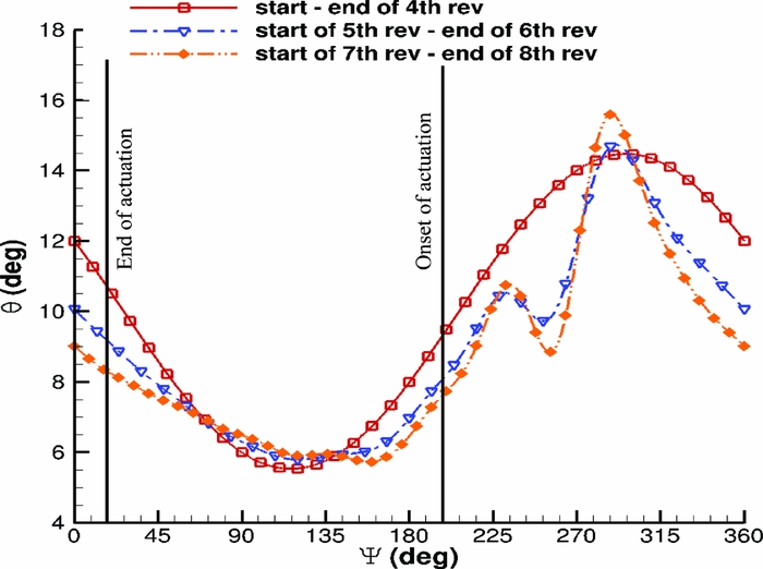
Figure 18. Pitching translating aerofoil - pitching schedule during control implementation.
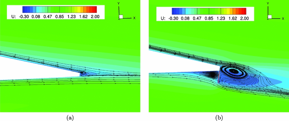
Figure 19. Pitching translating aerofoil - streamlines near the trailing edge of the clean aerofoil (a), and of the aerofoil with active Gurney flap (b), at
 $\Psi =360\,\text{deg}$
.
$\Psi =360\,\text{deg}$
.

Figure 20. Pitching translating aerofoil - streamlines near the trailing edge of the clean aerofoil (a), and of the aerofoil with active Gurney flap (b), at
 $\Psi =270\text{ deg}$
.
$\Psi =270\text{ deg}$
.

Figure 21. Pitching translating aerofoil - streamlines near the trailing edge of the clean aerofoil at (a)
 $\Psi =0\,\text{deg}$
, (b)
$\Psi =0\,\text{deg}$
, (b)
 $\Psi =187.5\,\text{deg}$
and (c)
$\Psi =187.5\,\text{deg}$
and (c)
 $\Psi =337.5\,\text{deg}$
.
$\Psi =337.5\,\text{deg}$
.
5.2 W3-Sokol closed loop control
Next, the pressure divergence criterion was used for the elastic W3-Sokol rotor at high advance ratio forward flight. The idea was to measure the pressure coefficient at different sections along the blade around the azimuth and identify Ψ, where part of the blade was experiencing stall. Figures 22 and 23 present the pressure coefficient at two different sections along the blade span. Based on that criterion, the new actuation schedule of the Gurney was defined, as presented in Fig. 24. It is observed that it is very similar to the one used in the previous section for the open loop control, but this time, the onset and end of the actuation took place earlier. The pressure distribution was also extracted after the actuation of the Gurney and at the end of the trimming process. Before trimming the rotor at the clean case thrust, setting the implementation of the Gurney leads the blade section in a deeper stall, while once the rotor was trimmed the blade was pitched down, and part of the initial stall was removed. As can be seen in Fig. 25, the maximum pressure coefficient has decreased significantly. This fact led to a further reduction of the torque requirement predicted during the open loop control for the same flight case, which is about 0.5%.

Figure 22. r/R = 0.4 - Pressure divergence around azimuth.

Figure 23. r/R = 0.65 - Pressure divergence around azimuth.
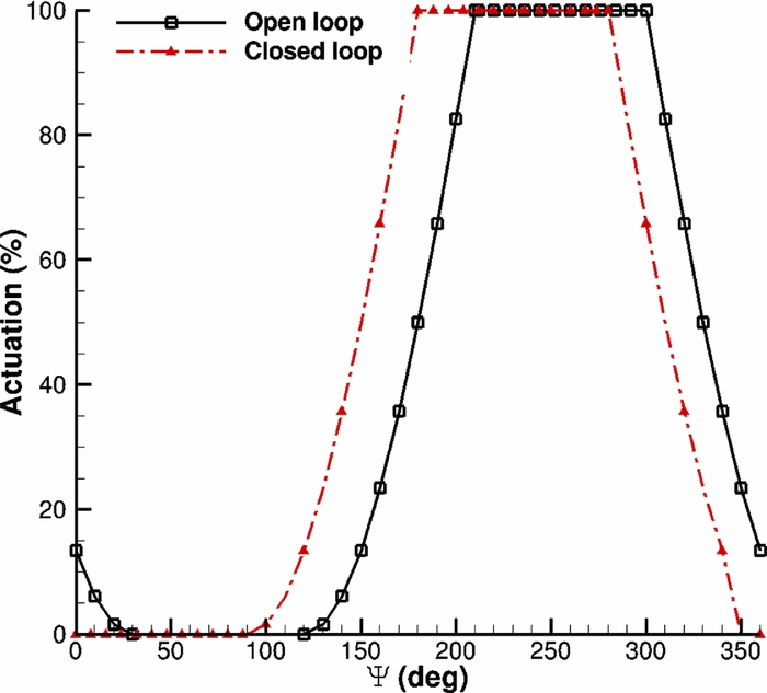
Figure 24. Gurney actuation schedule comparison against open loop.

Figure 25. r/R =0.5 - pressure divergence around azimuth with Gurney flap.
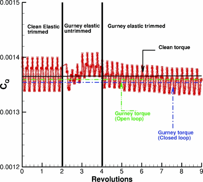
Figure 26. Torque requirement for closed loop actuation of the Gurney flap.
6.0 EFFECT OF GURNEY FLAP ON FULL HELICOPTER MODEL
This section describes the development of a simulation model for a Generic Light Utility Helicopter (GLUH)(Reference Garkushenko, Vinogradov and Barakos43). The model is built in FLIGHTLAB environment(44) for handling qualities and flight control investigations. For this final analysis, the elasticity of the blade was neglected, and none of the unsteady aero models available on FLIGHTLAB was activated. The Onera stall model was also used, but the final trim state was not significantly changed. This was done intentionally since the aim was to come up with an efficient, although approximate method for these computations. The main effect of the Gurney flap was, however, captured, even with this low fidelity method. The GLUH has a conventional configuration with high-mounted tail-boom carrying a fixed horizontal stabiliser and twin fins. The main rotor hub is a hingeless design with a torsion bar.
The blade element rotor model, that was used in this study, considers rotor dynamic degrees-of-freedom for each individual blade, either rigid or elastic. For this study a rigid blade was assumed. It computes the airloads with respect to the local angle-of-attack and Mach number and calculates blade dynamic response for nonuniform blade inertial and aerodynamic properties (e.g. chord and twist).
The blade element articulated rotor model includes blade hinges for feathering, flapping and lead-lag. The feathering hinge is modelled via control hinge, thus, has no degree-of-freedom, while the flap and lead-lag hinges are modelled with dynamic hinge of 1 rotational degree-of-freedom. Flap or lead-lag stop is modelled via nonlinear torsional spring/damping with further option of spring/damping dependence. The blade stop model table data are defined based on the blade flap or blade lag angle.
For the baseline model, a Quasi-Steady aerodynamic component was used for the airload calculation on the blade elements. The blade aerodynamic segments are defined based on the equal annuli area approach. This means that the segment length becomes finer towards the tip of the blade, while the aerodynamic loads are calculated by treating the blade sections as 2D panels, as described before.
The NACA23012M section was used, and the data were represented in table look-up form with lift, drag and pitching moment coefficients tabulated against angle-of-attack ( − 180–180º) and Mach number (0-0.9Mach). The GLUH model described in this work makes use of the Peters-He three state dynamic wake model. This model captures the uniform and first harmonic distribution of the inflow and the transient response of these inflow components in manoeuvring flight. This methodology also models the dynamic response of the inflow to manoeuvring flight and predicts the off-rotor components of inflow for use in interference modelling at the fuselage and tail.
FLIGHTLAB’s Bailey rotor component is used to model the tail rotor. In the Bailey model, closed form expressions for rotor thrust and torque are obtained analytically by integrating the airloads over the rotor blade span and averaging them over the azimuth. Only rotor coning is considered and, hence, there is no provision for blade cyclic pitch inputs. The induced velocity is computed from a uniform inflow model and included in the model. The following assumptions are employed in the derivation of the tail rotor equations:
-
1) constant chord and linear twist,
-
2) linear lift with lift curve slope,
-
3) incompressible flow,
-
4) no individual blade dynamics, except for the steady state coning, and
-
5) uniform induced flow over the rotor.
There are several modelling options available within FLIGHTLAB for the fuselage aerodynamics, including a panel method and a simple table look-up. For the Generic model, the table look-up option was chosen, where the fuselage coefficients are supplied by means of look-up tables as functions of angle-of-attack and sideslip angle(Reference Garkushenko, Vinogradov and Barakos43).
The GLUH model uses an NACA23015 aerofoil for the horizontal stabiliser and an NACA0012 for the vertical fins. Again, the aerodynamic loads were imported by the use of 2D look-up tables based on the performance of these aerofoils.
Regarding the powerplant, two gas turbine engines PW207K of PRATT & WITNEY company with takeoff power of 630hp esach were used. The engine was modelled using the ideal engine.
Modelling the aerodynamic interactions is a challenging aspect of rotorcraft simulation. A simple and effective way of interactional modelling is by incorporating look-up tables representing the downwash/upwash velocities at the respective aerodynamic surfaces, defined by the values of loads on the generating surface. In the absence of empirical/experimental data, the off-rotor induced velocity predicted by FLIGHTLAB’s inflow model is used for the calculation of the effect of the main rotor wake on fixed aerodynamic surfaces. From the finite-state dynamic wake equations, the induced velocity at an arbitrary flow field point can be computed(44). The Generic model utilises this finite-state dynamic inference model for the main rotor wake effects. The main rotor wake interference is applied to both the empennage and the fuselage.
6.1 FLIGHTLAB validation
Before testing the generic light utility model, FLIGHTLAB was validated using the UH-60 Black Hawk helicopter, and the results were compared against flight test data (Reference Kufeld, Balough, Cross, Studebaker, Jennison and Bousman45) and theory predictions. Figure 27 presents the power coefficient for different flight speeds. FLIGHTLAB gave good predictions between medium and high speed, although it did not agree with the flight test in hover case. Moreover, the accuracy of the calculation degrades at high gross weight the same way it was observed in previous study(Reference Yeo, Bousman and Johnson46).
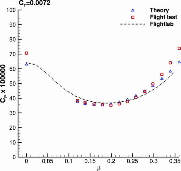
Figure 27. Power coefficient for UH-60 Black Hawk helicopter. FLIGHTLAB model against theory and flight test data(Reference Kufeld, Balough, Cross, Studebaker, Jennison and Bousman45).
6.2 Handling qualities
The main purpose of building this generic model was the observation of the Gurney flap effect on the trimming and the handling qualities of a helicopter. Typically, a 4/rev actuation of plain flaps has been used on rotorcraft. However, in this study a 1/rev actuation was implemented, which could introduce additional moments on the helicopter and result in difficulties during trimming or deterioration of the handling qualities. A comparison between nonlinear response of the body pitch rate and acceleration to a sinusoidal collective input is presented in Fig. 28 to evaluate the effect of a controller with the observers(Reference Garkushenko, Vinogradov and Barakos43) against a simple Proportional-Integral-Derivative (PID) controller. The behaviour of the two systems was very different. The main difference is observed on the stability. When the PID is used, the model becomes very unstable, and once it starts diverging from the trim condition, it never goes back to the equilibrium point. However, when the robust controller is implemented, the model becomes stable again and it goes back to the equilibrium within a very short time. Regarding the handling qualities of the model, FLIGHTLAB is, in general, able to derive them. However, only one of the available tests produced meaningful results and it is used to compare the effect of the designed controller on improving the manoeuvrability of the rotorcraft. This test was related to hover and low speed requirements and especially to small-amplitude pitch (roll) attitude response to control inputs. Based on ADS-33E-PRF(Reference Baskett47), this criterion has requirements on bandwidth and phase delay to prevent tendency of Pilot-Induced Oscillation (PIO). The mid-term response characteristics shall apply at all frequencies below the bandwidth frequency. FLIGHTLAB generated the damping ratio of roll attitude response ζ, and the natural frequency of roll attitude response ω
n
for the model with and without the designed controller. For the case without the controller, the following results were obtained: ζ = 0.12 and
 $\omega _{n} = 2.89 \,\text{rad/s}$
, while for the case with the controller, it produced ζ = 0.40 and ω
n
= 0.39. Based on the Aeronautical Design Standard Performance Specification ADS-33E-PRF(Reference Baskett47), the limits on pitch (roll) oscillations are presented below. According to those limits, the model can not be qualified (level is greater than 3), but when the controller is used, the level improves to level 1. This fact clearly presents the ability of the designed controller to improve the dynamic characteristics of the rotorcraft. Moreover, when the Gurney flap is implemented in the model the result in Fig. 29 clearly shows that it does not affect the rotorcraft handling qualities.
$\omega _{n} = 2.89 \,\text{rad/s}$
, while for the case with the controller, it produced ζ = 0.40 and ω
n
= 0.39. Based on the Aeronautical Design Standard Performance Specification ADS-33E-PRF(Reference Baskett47), the limits on pitch (roll) oscillations are presented below. According to those limits, the model can not be qualified (level is greater than 3), but when the controller is used, the level improves to level 1. This fact clearly presents the ability of the designed controller to improve the dynamic characteristics of the rotorcraft. Moreover, when the Gurney flap is implemented in the model the result in Fig. 29 clearly shows that it does not affect the rotorcraft handling qualities.
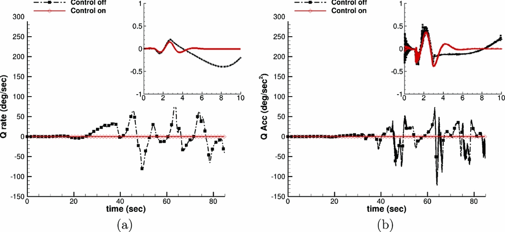
Figure 28. Nonlinear response of (a) body pitch rate and (b) body pitch acceleration to sinusoidal collective input. “Control off”, “Control on” correspond to PID and controller with observers, respectively.
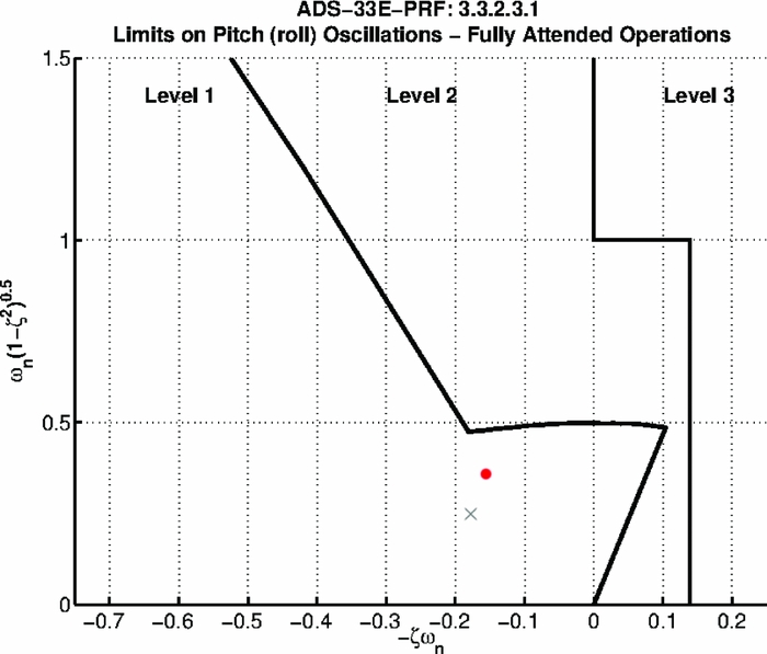
Figure 29. Limits on pitch (roll) oscillations - hover and low speed. Red dot represents the clean rotor, while cross represents the rotor with the active Gurney flap.
7.0 CONCLUSIONS AND FUTURE WORK
In this work, the effect of the Gurney flap on the overall flight envelope of a helicopter was studied. The Gurney flap on W3-Sokol blade in hover did not change the maximum figure of merit, but it enhanced it at medium to high thrust settings. The power requirement was also decreased in such a way that for the typical thrust case, the rotor increased its loading capability by 220kg.
In forward flight, the flap was used efficiently to alleviate the retreating blade stall. The W3-Sokol was studied again at high speed flight, and the Gurney removed most of the separated flow. As a result, the rotor torque decreased by 3.3%. The flap was tested at two flight speeds and two thrust settings as flight test data were available, and it proved to be effective above μ = 0.11 at maximum gross weight of the helicopter.
Some significant remarks regarding the stall identification and the actuation of the Gurney flap were observed. The active actuation of the flap can be implemented on real helicopters by observing the pressure on the suction side of the rotor blades. If the pressure diverges from a threshold, then the flap would be actuated. This 1/rev actuation might cause vibration issues and alter the trimming capability of the helicopter. For that reason, a generic light utility helicopter was built and tested on FLIGHTLAB with and without an active Gurney. The results showed that the flap will change neither the trimming ability of the model nor its handling qualities if there is a robust controller on the helicopter. Another issue was the possible effect of the flap on the structural dynamics of the blade. Thus, 10% of the original mass of the blade was distributed additionally on the blade, along the location of the Gurney, and a static analysis was conducted. The mode shapes of the blade were not affected by the flap, while the frequencies of the modes at the nominal rotor speed were decreased by less than 2%. In fact, the uncertainty due to the Gurney was of the same order of magnitude of the one introduced by different tip-shape designs tested for an S-76 blade.
To conclude, the potential effect of an active Gurney flap on the main rotor as well as on the response of the helicopter were studied using coupled fluid-structure dynamics. It was shown that the flap can enhance the performance of helicopters, especially at high thrust requirements, as it is an efficient flow control device for retreating blade stall alleviation. Some of the observed benefits are due to the aeroelastic re-shaping of the blade due to the pitching moments induced by the flap. However, experimental data on rotors with active Gurney flaps are essential for further validation of the code and understanding of the Gurney effect on rotor aerodynamics.
Future efforts should be directed towards the addition of the fuselage in CFD computations to study its interaction with the altered rotor wake due to the Gurney. Moreover, the effect of the flap can be further optimised by implementing multiple flaps along the rotor blade. Apart from the pressure divergence criterion that was put forward to detect stall, other criteria should also be investigated. Finally, the active Gurney flap should be considered as a means to off-load the advancing side of the rotor, and its effect should be investigated on rigid blades, as well.
ACKNOWLEDGEMENTS
The financial support via the IMESCON Marie Curie ITN project (grant agreement number: 264672), the release of the W3 Sokol main rotor blade geometry by PZL Swidnik, the use of the computing centre TASK of Gdansk, Poland, and the contribution of Axsym Engineering in the post-processing of the flight test data are gratefully acknowledged. Some of the CFD results were obtained using the Jupiter cluster of CFD Lab of University of Glasgow and the EPSRC funded ARCHIE-WeST High Performance Computer (www.archie-west.ac.uk). EPSRC grant number: EP/K000586/1.


