


Introduction
Due to the increasing demand for higher data rates and bandwidth, the next generation of mobile communications (5G) is migrating to millimeter wave (mmW) frequencies. To overcome the innate high path loss and atmospheric absorption at these frequency bands, highly directional transmission is necessary. Therefore, adaptive antenna arrays with efficient beamforming network (BFN), as well as good beam steering capabilities, are employed to combine signals of antenna array elements into a pattern, which is more directive than the single element pattern. A BFN usually consists of a set of input and output ports arranged along an arc. Each input port at the focal surface produces a desirable amplitude and phase distribution so that the beam is directed into a specific angle.
The concept of microwave lens was introduced in 1950 [Reference Ruze1]. This concept was later used by Rotman and Turner to introduce the first three-focal-point lens-based BFN, known as Rotman lens, to feed linear arrays [Reference Rotman and Turner2]. It is composed of a parallel conducting plate fed by horn antennas along the beam contour. Transmission lines were used to connect the inner receiver contour and the outer phased arrays. The three focal points on the beam contour generate zero theoretical phase errors along the phase front of the array. In the initial design, air-filled parallel plate, the beam contour was circular and the array scan angle was equal to the subtended beam port angle. Due to simplicity, reliability, and wide-scanning angle over a broad frequency bandwidth [Reference Dong, Zaghloul and Rotman3], the original Rotman lens design has been the bench mark for many later studies and modifications, such as size reduction [Reference Archer and Maybell4], scan angle increment [Reference Smith5–Reference Gagnon7], side wall absorption reduction [Reference Musa and Smith8, Reference Musa and Smith9], maximizing the coupling power from the feed contour to the array contour [Reference Singhal, Sharma and Gupta10], and phase performance improvement [Reference Dong, Zaghloul and Rotman11].
One important design parameter, which could degrade the system performance in case of inefficient design, is the phase error that implies on the aperture of the array antenna [Reference Vashist, Dutta and Soni12]. Accordingly, the lens design should be optimized for the minimum possible phase error. Some research efforts have been reported on phase error reduction and optimization. In [Reference Katagi, Mano and Sato13] phase errors reduction was performed by introducing the ratio of the scan and beam subtended angles (γ), which provided a new degree of freedom compared with the conventional design. In [Reference Rappaport and Zaghloul14], path length errors for two-dimensional scanning were reduced by replacing the planar feed locus with a curved feed locus. In conventional Rotman lens [Reference Rotman and Turner2], the beam and array contours are assumed to be circular. In [Reference Hansen15], Hansen reduced the phase errors by introducing an elliptical beam contour. For each beam direction in [Reference Uyguroglu and Oztoprak16, Reference Uyguroglu, Oztoprak and Ergun17], feed curve points were obtained assuming zero path length error at three chosen points of the radiating array. In [Reference Dong, Zaghloul and Rotman3], a non-focal design scheme was applied to produce minimum average phase errors for all beam ports, rather than achieving zero-phase error for only selected focal points. In [Reference Rajabalian and Zakeri18], the symmetry of non-focal lens is introduced, so that the input ports and output ports can be interchangeable. In [Reference Park and Park19], the phase errors are minimized by finding the optimal values of off-center focal angle (α), On-axis focal length (f) and ray to beam angle ratio (γ) and moving off-axis focal points along a beam curve. In [Reference Rajabalian and Zakeri20, Reference Rajabalian and Zakeri21], a three-focal lens was converted to a non-focal lens by optimizing the length of the transmission lines in three-focal scenario, using particle swarm optimization, and updating the location of input and output ports. The method, demonstrated in [Reference Attaran, Rashidzadeh and Kouki22], did reduce the phase error based on ray optics theory for determining the beam's location. In [Reference Darvazehban, Manoochehri, Salari, Dehkhoda and Tavakoli23], genetic algorithm is used to optimize the position of the lens input and output ports for minimum phase error. Table 1 summarizes the results of these published efforts.
Table 1. Comparison of path length error reduction and design methodology of some Rotman lenses in literature

In this paper, we introduce a novel design of a Rotman lens for 5G applications, in terms of reducing the phase error at the output ports over a wideband operational frequency. The proposed lens covers the frequency bands considered by the Federal Communications Commission (FCC) for next-generation Mobile Radio Services, i.e. 24.25–24.45 GHz, 25.05–25.25 GHz, and the Local Multipoint Distribution Service (LMDS) frequency bands operating at frequencies 27.5–28.35 GHz, 29.1–29.25 GHz, and 31–31.3 GHz [24]. A new design scheme is applied to minimize the phase errors on the aperture of the array antenna. By employing particle swarm optimization, the optimal values of some design parameters (i.e., eccentricity, focal to aperture length ratio, focal ratio, and off-center focal angle) are obtained, so that the corresponding input and output ports provide the minimum path length errors on the aperture of the array antenna. Because the optical path length equality and the lens geometry are used to calculate the optimization cost function, the input and output ports are indirectly involved in the optimization process.
Rotman lens structure
The structure of a microstrip Rotman lens is shown in Fig. 1. It usually consists of M number of input ports and N number of output ports to feed N number of array elements [Reference Archer25]. The signal applied to each input port is transmitted and picked up by all the output ports. A linear progressive phase shift is generated across the output ports of the lens due to the electrical length difference between each input port and all output ports. Rotman lens is considered as a true-time delay device as the desired phase front at the array input is provided by applying path delay mechanism within the lens cavity [Reference Jafari, Liu and Morgan26]. The path-length design mechanism in the lens is independent of frequency [Reference Archer25]. This characteristic makes it ideal for many broadband applications which require wide-angle scanning over a broad frequency bandwidth [Reference Hawesand and Liu27, Reference Archer28]. To reduce the standing waves and multiple reflections, absorptive ports (dummy ports) are applied as shown in Fig. 1.
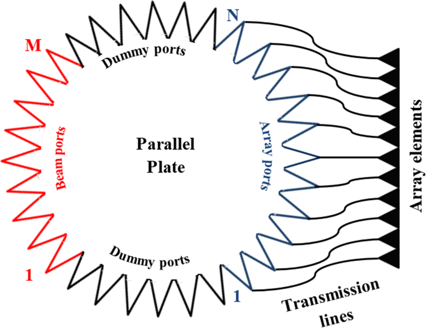
Fig. 1. Structure of a microstrip Rotman lens.
The schematic geometry of a trifocal Rotman lens is shown in Fig. 2 and its defining geometrical parameters are presented in Table 2. The input and output ports are located on C B and C A, respectively. On-axis focal point F 0 and off-axis focal points F 1 and F 2 are located on the beam contour at angles of 0, +α, and −α respectively, i.e. the coordinates of ( − f 0, 0), ( − f cos α, f sin α), and ( − f cos α, − f sin α) [Reference Rotman and Turner2].
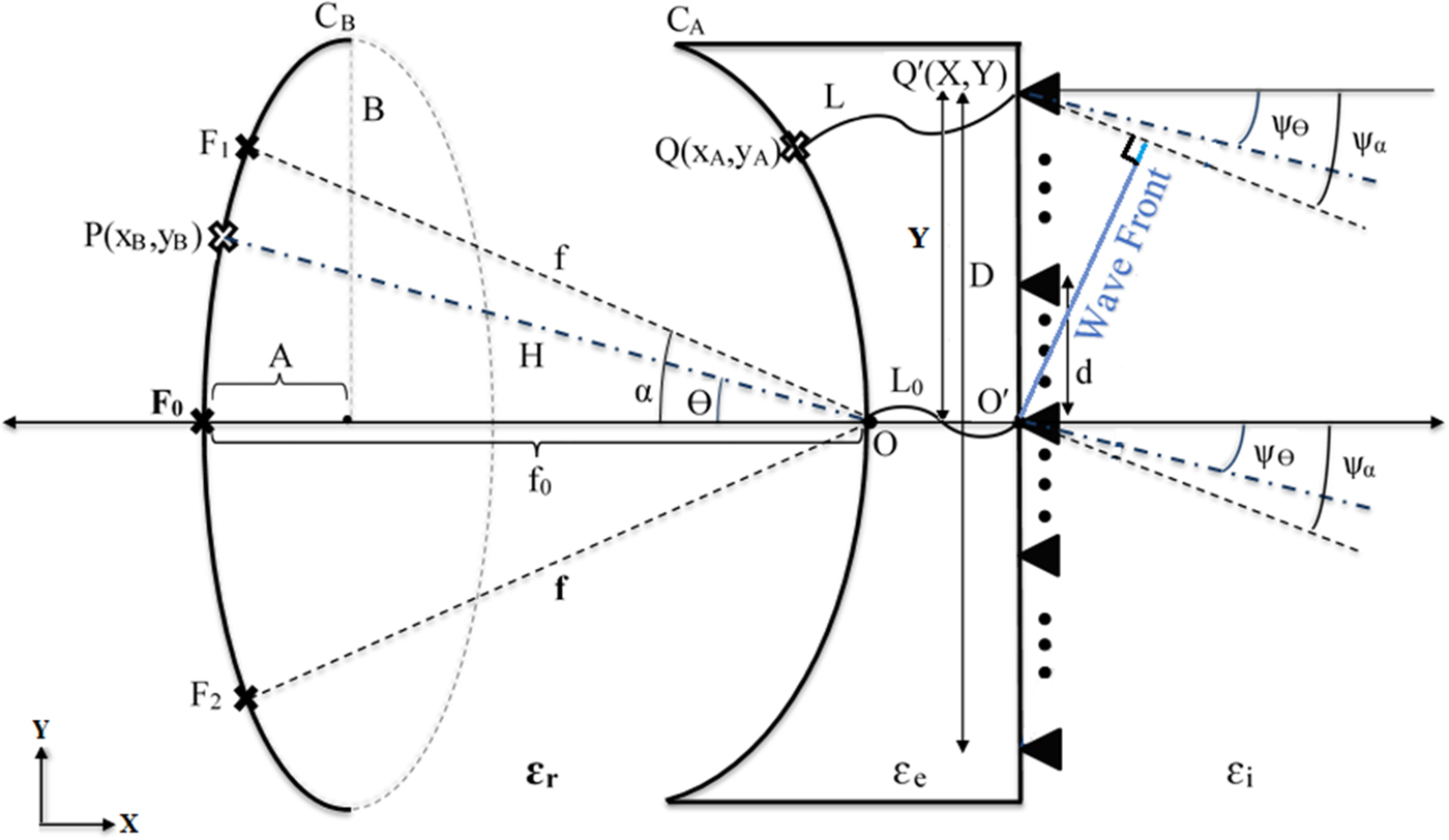
Fig. 2. The schematic geometry of a trifocal Rotman lens.
Table 2. Geometrical parameters of a trifocal Rotman lens

Using optical path length equality [Reference Rotman and Turner2, Reference Dong, Zaghloul and Rotman3, Reference Pozar29], the quadric lens equation can be derived as:
 $$\eqalign{ & \displaystyle{{a\varepsilon _e} \over {\varepsilon _r}}L_N^2 + b\sqrt {\displaystyle{{\varepsilon _e} \over {\varepsilon _r}}} L_N + c = 0 \cr & \left( {L_N} \right)_{1,2} = \sqrt {\displaystyle{{\varepsilon _r} \over {\varepsilon _e}}} \displaystyle{{ - b \pm \sqrt {b^2 - 4ac}} \over {2a}},} $$
where
 $$\eqalign{a = & - 1 + \left( {\displaystyle{{1 - \beta} \over {1 - \beta \cos \alpha}}} \right)^2 + \displaystyle{{\varepsilon _i} \over {\varepsilon _r}}\left( {\displaystyle{{Y\gamma} \over {\beta f_0}}} \right)^2, \cr b = & - 2 + \displaystyle{{2\varepsilon _i} \over {\beta \varepsilon _r}}\left( {\displaystyle{{Y\gamma} \over {\,f_0}}} \right)^2 + \displaystyle{{2\left( {1 - \beta} \right)} \over {1 - \beta \cos \alpha}} - \displaystyle{{\varepsilon _i} \over {\varepsilon _r}}\left( {\displaystyle{{Y\gamma \sqrt {1 - \beta} \sin \alpha} \over {\,f_0\left( {1 - \beta \cos \alpha} \right)}}} \right)^2, \cr c = & \displaystyle{{\varepsilon _i} \over {\varepsilon _r}}\left( {{\left( {\displaystyle{{Y\gamma} \over {\,f_0}}} \right)}^2 - \displaystyle{{{\left( {Y\sin \psi _a} \right)}^2} \over {\,f_0^2 \left( {1 - \beta \cos \alpha} \right)}} + \displaystyle{{{\left( {Y\sin \psi _a} \right)}^4} \over {4\varepsilon _rf_0^4 {\left( {1 - \beta \cos \alpha} \right)}^2}}} \right).} $$
The array port positions, x A and y A, are obtained as
 $$\eqalign{x_A = & \displaystyle{{L_N\left( {1 - \beta} \right)} \over {\beta \cos \alpha - 1}}\sqrt {\displaystyle{{\varepsilon _e} \over {\varepsilon _r}}} + \displaystyle{{\varepsilon _iY^2{\sin} ^2\psi _a} \over {2\varepsilon _rf_0^2 \left( {\beta \cos \alpha - 1} \right)}}, \cr y_A = & \displaystyle{{Y\gamma} \over {\,f_0}}\sqrt {\displaystyle{{\varepsilon _i} \over {\varepsilon _r}}} \left( {1 - \displaystyle{{L_N} \over \beta} \sqrt {\displaystyle{{\varepsilon _e} \over {\varepsilon _r}}}} \right).} $$
In order to have wide angle scanning capabilities, it is necessary to place some other feeds at non-focal points. This causes a phase error in the corresponding wave front [Reference Hansan30]. Ellipse equation is used to obtain these non-focal feed points, i.e. (x B, y B) as:
 $$\eqalign{x_B = &\, \displaystyle{{A - 1 + \sqrt {A^2 + 1 - 2A + \left( {2A - 1} \right)\left[ {tg^2\theta \left( {1 - e^2} \right) - 1} \right]}} \over {1 + \left( {1 - e^2} \right)tg^2\theta}}, \cr y_B = & - x_B\left( {tg\theta} \right).} $$
where A and B are the semi-minor and semi-major axes of the beam contour ellipse respectively and e is the ellipse eccentricity that measures how much the conic section deviates from being circular.
 $$\eqalign{B = & \displaystyle{1 \over 2}\displaystyle{{ - f_0^2 \,\beta^2\,{\cos} ^2\alpha + 2 \beta \ f_0\cos \alpha + f_0^2 \beta ^2\left( {e^2 - 1} \right){\sin} ^2\alpha - 1} \over {\sqrt {1 - e^2} \left( {\,f_0\beta \cos \alpha - 1} \right)}}, \cr A =\ & B\sqrt {1 - e^2}} $$
Rotman lens design using particle swarm optimzation
Particle swarm optimization is a population-based evolutionary search algorithm that solves numerical problems by using the directional information to locally converge to the target value.
In this optimization technique, the population, known as a swarm, is composed of search points, known as particles. Each particle has a position and a velocity for each of its dimensions. The optimum is looked for by iteratively updating the swarm. In each iteration, the movement of the swarm is guided by updating the velocity of each particle according to its personal best position (pbest), i.e. the position at which each particle achieved the best solution up to the current iteration, and the global best position of the entire swarm (gbest), i.e. the position at which the best fitness value has been obtained so far by any particle among pbests [Reference Zhang, Wang and Jil31]. This iterative process is repeated until a termination criterion is met, i.e. the maximum defined number of iterations is performed or an optimum solution is eventually achieved. Particle swarm optimization (PSO) has some advantages compared with other optimization techniques (e.g., genetic algorithm (GA) technique), which are mainly in its algorithmic simplicity and its ability to control convergence [Reference Rahmat-Samii32]. PSO is based upon the behavior of social swarm, which requires only one operator, i.e., velocity. On the other side, GA is based on genetic coding and natural selection, which requires three operators of selection, crossover, and mutation [Reference Rahmat-Samii32].
We used PSO algorithm, implemented on MATLAB, to avoid time-consuming in using the commercial software optimization process. In the study under consideration, the search space consists of four-dimensional particles, i.e. each particle is an array of four parameters. These four parameters, namely e, F D, β, and α are considered optimization parameters since they have a direct effect on the shape of the beam and array contours, port positions, and the phase performance of the lens [Reference Rotman and Turner2].
Total path length difference to the phase front is considered for minimization to evaluate the achieved parameters in each iteration. For each port position on the beam contour, P(x B, y B), a path length error can be obtained by the difference in path length from P through Q and Q′ to the phase front, and from P through O and O′ to the phase front:
 $$\Delta l = PQ\sqrt {\varepsilon _r} + L\sqrt {\varepsilon _e} + Y\sqrt {\varepsilon _i} \sin \psi _\theta - \left( {PO + L_0} \right),$$
where Q(x A, y A) is any port position along the array contour and Y is the coordinate of the corresponding element on the antenna array.
Particles move through the search space and look iteratively for the optimum values of e, F D, β, and α by which the optimum port positions and transmission line lengths are calculated, i.e. the total path length error and phase error are minimized.
Figure 3 illustrates the flowchart of the proposed procedure. After defining the design parameters and the initial values, the positions of the array ports, beam ports, and transmission lines lengths are exactly obtained from (1) to (5). In the next step, the path length errors are obtained using (6) and summed up to obtain the total path length error. The optimization parameters are then updated using PSO algorithm and substituted in (1)–(5) to update port positions and transmission lines lengths. This procedure is continued so that the minimum total path length error is achieved. In the last step, the optimum port positions and transmission line lengths that provide the minimum total path length error are saved.

Fig. 3. The proposed optimization procedure.
Based on measurements and analysis performed by NYU Wireless for 5G communications [Reference Rappaport, Sun, Mayzus, Zhao, Azar, Wang, Wong, Schulz, Samimi and Gutierrez33–Reference Samimi, MacCartney, Sun and Rappaport47], it is recommended that the base station antenna should achieve a high gain of 20 dBi at the broadside direction, and a look angle of 60° based on beam steering capability with steps of 8°–10° in azimuth plane. Consequently, seven steered beams of a10° step (i.e., −30°, −20°, −10°, 0°, +10°,+20°, and +30°) are needed, which are implemented by placing seven input ports in the proposed Rotman lens. Moreover, the 1 × 4 subarray antenna, which is designed for wideband 5G applications and is presented in [Reference Ershadi, Keshtkar, Abdelrahman and Xin48], achieves a gain of more than 11 dBi over the entire band. Based on array theory [Reference Balanis49], eight elements separated by a half-wavelength achieves an array factor of 10*log(8) = 9 dB. Accordingly, eight of this subarray antenna can achieve the required gain of 20 dBi, which is implemented by defining eight output ports in the proposed Rotman lens. The design criteria chosen to minimize the phase error in the lens and the geometrical and electrical properties of the dielectric substrate (RT Duroid 5880) are listed in Table 3.
Table 3. Specification of the desired 5G Rotman lens

The parameters of the PSO algorithm and their values are listed in Table 4. Path length error is considered for minimization in the optimization process. As shown in Fig. 4, the optimization process stops after 76 iterations when the value of the objective function, i.e. the total path length error, stops improving 0.4404 mm.

Fig. 4. The iterative optimization process.
Table 4. Parameters of the PSO algorithm

The optimized parameters and their values are listed in Table 5, and the position of the input and output ports, as well as the transmission line lengths, are listed in Table 6.
Table 5. Optimized parameters

Table 6. Port positions and transmission line length

Simulation and measurement results
To validate the proposed optimization process, the optimized Rotman lens is first simulated using HFSS simulation software and then fabricated and measured according to the port positions and the transmission line lengths mentioned in Table 6. The simulated model and fabricated prototype are illustrated in Fig. 5.
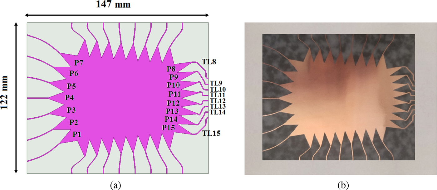
Fig. 5. Proposed 7 × 8 Rotman lens; (a) Simulation model and (b) fabricated prototype.
Figure 6(a) depicts the phase error between the beam-ports and the array-ports of the proposed optimized lens. As observed, the phase error of the focal ports (i.e. ports 1, 4, and 7), are approximately zero, whereas the phase error is increased at the other ports. The aim of the proposed method is to minimize the phase error of all ports.

Fig. 6. (a) Phase error at the array ports (b) Comparison of the maximum phase errors of the proposed lens with conventional three-focal circular and elliptical lenses.
Figure 6(b) compares the maximum phase errors of the lens designed by the proposed method with the conventional three-focal circular and elliptical designs. As can be seen, the proposed optimization reduces the maximum phase error to <0.1°, i.e. 3–5 times better than the conventional methods. This reduction in phase error guarantees precise beam-steering capability when the lens feeds an antenna array, as shown in Fig. 7. This figure presents the array factor patterns, based on applying the phase control capability of the proposed lens on a linear array of eight elements separated by a half-wavelength at the center frequency, i.e., 28 GHz. As seen, the proposed lens can achieve a scanning range of ± 34° with steps of approximately 8.3°. A comparison of array factors of the proposed lens and conventional circular and elliptical lenses are demonstrated in Fig. 7(b) and Table 7. As seen, the produced beam angles are very close to the ideal condition, where the array factor varies up to 1.6 dB at broadside over the operational bandwidth, i.e. 25–31 GHz.

Fig. 7. Array factor (a) Proposed lens (b) Comparison with conventional circular lens.
Table 7. Angle of the produced beam in different lenses

Figure 8 shows the simulated and measured reflection coefficients of ports 1–4 of the proposed lens. Due to symmetry, the reflection coefficient of ports 5–7 are equal to ports 3–1, respectively. An average impedance bandwidth of 21.4% (25–31 GHz) is achieved. The obtained wide bandwidth covers most of the mmW Gbps Broadband (MGB) candidates, considered by the FCC for next-generation Mobile Radio Services, i.e. 25.05–25.25 GHz and the LMDS frequency bands operating at frequencies 27.5–28.35 GHz, 29.1–29.25 GHz, and 31–31.3 GHz. Simulation and measurement results of the maximum phase errors at the output ports are shown in Fig. 9, so that all frequency bands recommended by FCC are demonstrated. As seen, the measurement results are in good agreements with simulations, thereby validating the precise phase control capability of the proposed Rotman lens, which ensures a beam steering functionality when connected to an antenna array.

Fig. 8. Reflection coefficient of the proposed optimized lens (a) port 1, (b) port 2, (c) port 3, (d) port 4.
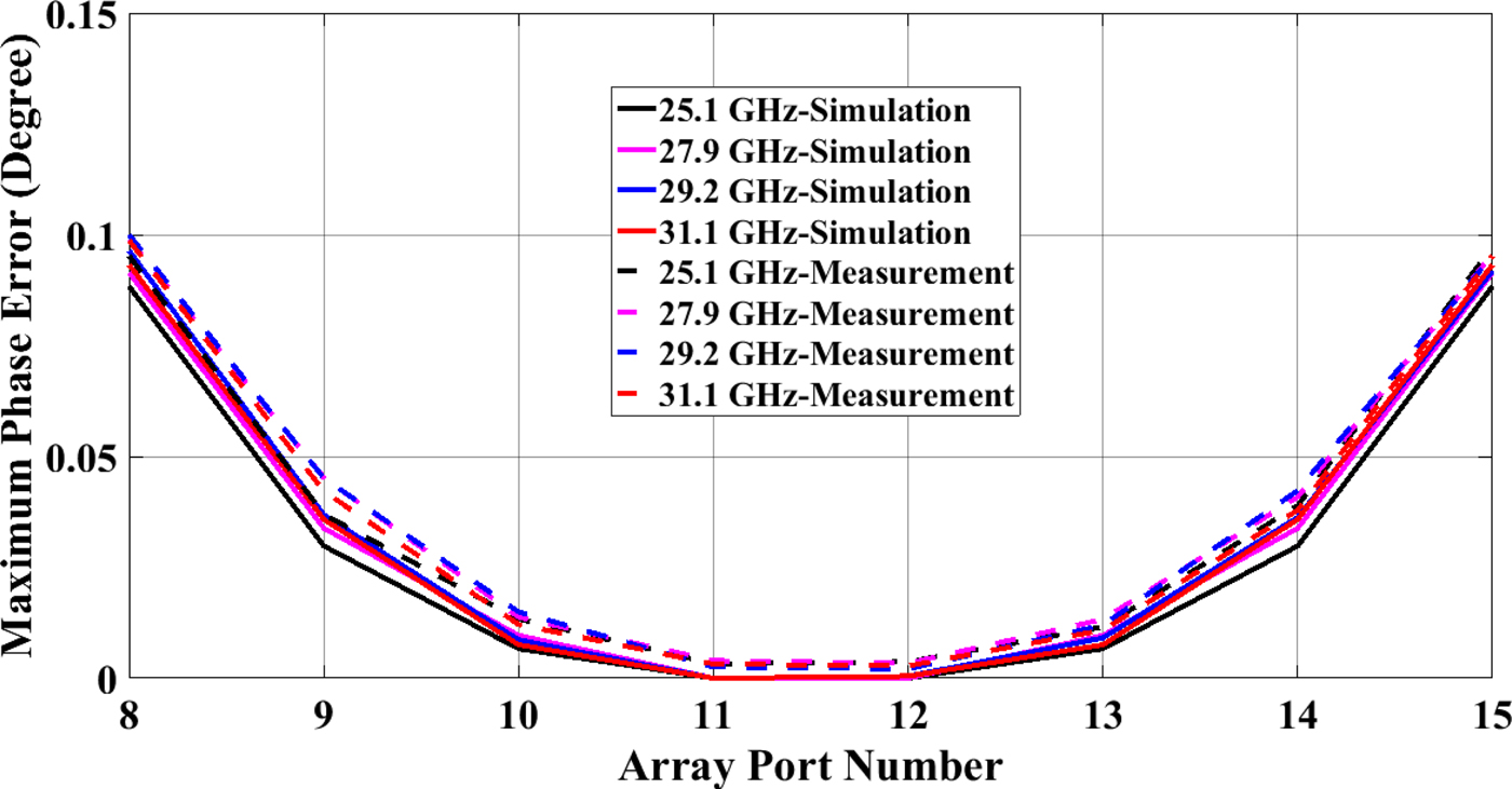
Fig. 9. Maximum phase error at the output ports, for the center frequencies recommended by FCC.
Figure 10 shows the distribution of the current propagating through the lens when ports 1–4 are excited separately. It can be observed that the wave front arrives at all the array ports as most of the electric field propagates to output ports, scattered waves are absorbed in dummy ports and coupling effect between input ports is nearly zero.
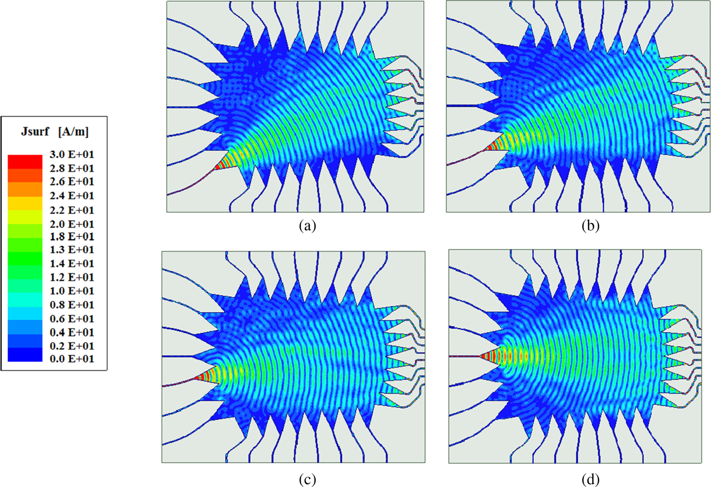
Fig. 10. Current distribution of the proposed optimized Rotman lens with (a) Port 1, (b) Port 2, (c) Port 3, (d) port 4 excited.
Conclusion
In this paper, the parallel plate of Rotman lens is optimized for minimum phase error by applying PSO algorithm over four geometrical parameters, i.e. eccentricity (e), focal to aperture length ratio (F D), focal ratio (β), and off-center focal angle (α). Input and output port positions, and transmission lines lengths were then calculated by the three-focal scenario. To evaluate the proposed method, full-wave simulation of a Rotman lens with 7 input and 8 output ports was performed at 28 GHz followed by fabrication of the simulated model. The proposed optimization technique reduces the maximum phase error to <0.1°, i.e. 3–5 times reduction in the maximum phase error. The lens showed an ability to scan −34° to 34° with steps of 8.3° and with beam angles which are very close to the ideal condition in comparison with conventional lenses in literature. Moreover, the proposed design achieves a wide impedance bandwidth of approximately 21.4% (25–31 GHz), which covers most of the mmW Gbps Broadband frequency bands considered by the FCC for next-generation Mobile Radio Services. The proposed Rotman lens can be integrated with wideband microstrip patch antenna arrays which are suitable for 5G mmW applications.
 Seyyedehelnaz Ershadi received her B.S. and M.S. degrees from Islamic Azad University, Tehran, Iran, in 2006 and 2009, respectively. In 2014 she was awarded a scholarship by the Ministry of Science, Research and Technology of the Islamic Republic of Iran to carry out her Ph.D. research work as a research scholar at the Microwave and Millimeter Wave Laboratory, University of Arizona. She is currently studying for a Ph.D. degree in communication engineering from Imam Khomeini International University. Her main research interests include antennas, antenna arrays, millimeter wave, and 5G and broadband communications.
 Asghar Keshtkar was born in Ardabil, Iran, in 1962. He received the B.Sc. degree in electrical engineering from Tehran University, Tehran, Iran, the M.Sc. degree in electrical engineering from the University of Khaje-Nasir, Tehran, and the Ph.D. degree in electrical engineering from the Iran University of Science and Technology, Tehran, in 1989, 1992, and 1999, respectively. He is currently a Professor with the Faculty of Engineering and Technology, Imam Khomeini International University (IKIU), Ghazvin, Iran. His current research interests include electromagnetics, bioelectromagnetics, and electromagnetic launchers and antennas.
 Alireza Bayat received B.E. degree in communication engineering from Andhra University, Visakhapatnam, India, in 1987; the M.Tech. and the Ph.D. degree in electrical and communication engineering from the University of IIT Banaras Hindu, Varanasi, India, in 1989, 1992, respectively. He is currently an Assistant Professor with the Faculty of Engineering and Technology, Imam Khomeini International University, Qazvin, Iran. His research interests include electromagnetic, radar, bio-electromagnetic, antenna, and EMC.
 Ahmed H. Abdelrahman received B.S. and M.S. degrees from The Department of Electrical Engineering, Electronics and Communications, Ain Shams University, Cairo, Egypt, in 2001 and 2010, respectively, and he received a Ph.D. degree in engineering sciences from The Department of Electrical Engineering, University of Mississippi, University, MS, USA, in 2014. Dr. Abdelrahman is currently a research associate with the Antenna Research Group (ARG), in The Department of Electrical, Computer, and Energy Engineering, at The University of Colorado Boulder, Boulder, CO, USA. His research interests include transmitarray/reflectarray antennas, mobile antennas, reconfigurable antennas, simultaneous transmit and receive (STAR) antennas, satellite communications, and thermoacoustic and millimeter-wave imaging. Dr. Abdelrahman was the recipient of the several prestigious awards, including the Third-Place Winner Student Paper Competition Award at the 2013 ACES Annual Conference, and the Honorable Mention Student Paper Competition at the 2014 IEEE AP-S International Symposium on Antennas and Propagation.
 Hao Xin received the Ph.D. degree in physics from the Massachusetts Institute of Technology (MIT), Cambridge, MA, USA, in 2001. He performed research studies for 5 years in MIT's Physics Department and at Lincoln Laboratory, where he investigated power dependence of the surface impedance of high-Tc superconducting films and Josephson junction properties at microwave frequencies. From November 2000 to November 2003, he was a Research Scientist with the Rockwell Scientific Company, Thousand Oaks, CA, USA, where he conducted research as Principal Manager/Principal Investigator in the area of electromagnetic band-gap surfaces, quasi-optical amplifiers, electronically scanned antenna arrays, and MMIC designs using various III–V semiconductor compound devices, and random power harvesting. From 2003 to 2005, he was a Sr. Principal Multidisciplinary Engineer at Raytheon Missile Systems, Tucson, AZ, USA. He is now a Professor and Director of the Cognitive Sensing Center in the Electrical and Computer Engineering Department and Physics Department at the University of Arizona, Tucson, AZ, USA. He has published more than 270 refereed technical papers in the areas of solid-state physics, photonic crystals, and the applications thereof in microwave and millimeter wave technologies. He has 13 patents issued and one pending in the areas of photonic crystal technologies, random power harvesting based on magnetic nano-particles, and microwave nano-devices. His current research focus is in the area of microwave, millimeter wave and THz technologies, including solid-state devices and circuits, antennas, passive circuits, 3-D-printed EM components and systems, and applications of new materials, such as metamaterials and carbon nanotubes.


