Introduction
The testing of electromagnetic compatibility (EMC) must be conducted under specialized conditions for both emission and immunity testing. Such test facilities should enable measurement without influence from the ambient environment. However, when measuring in an open area, the measurement may be invalidated due to the influence of undesired signals e.g. from broadcast stations, cellular network etc., which can operate at the same frequency as the measured signal. Conversely, signals emitted by the tested equipment cannot disrupt other electronics located in the near vicinity. This problem is especially important when tested devices emit strong signals, such as high power microwaves (HPM) pulses [Reference Nowosielski and Łopatka1, Reference Nowosielski, Przesmycki, Wnuk and Rychlica2].
EMC tests are usually performed in screened rooms, such as anechoic chambers or semi-anechoic chambers. These rooms are shielded with specialized absorbers. Shielding is most effective when two types of absorbers, such as heavy ferrite tiles and delicate graphitic cones, are used simultaneously. However, such equipment is intended for indoor use. In open-area test facilities, for practical reasons, one is usually limited to screened curtains, tents or light, and portable structures. The walls of commercially available curtains or tents are generally made of conductive layers and therefore, reflect all incident rays (just like a metal sheet would), yielding to wave-standing environment conditions. Such test sites can be used to reduce external radiation but make it very difficult to obtain a reflection-free area inside the room.
Therefore, there is a need to develop a new type of absorbing material. Such material needs to have good shielding properties, i.e. must be highly absorptive, must have low reflectivity, and must exhibit good mechanical properties and flexibility.
The important problem in any open-area test site is to reduce the reflection of rays from the ground. When testing an antenna in an anechoic chamber, to ensure a reflection-free from the ground, the floor should be covered by ferrite tiles. However, ferrite absorbers guarantee good absorbing properties only for frequencies below several hundred megahertz. For higher microwaves, the ferrite materials lose their magnetic properties and cannot effectively function as absorbers. On the other hand, well-known microwave absorbers, such as graphite cones, cannot be used to cover the ground of the test site due to their delicate structure. An effective material for a floor absorber should have low reflectivity properties as well as good mechanical characteristics.
The main idea regarding the investigated material is to use it in an open space for the purposes of HPM-testing. Currently, the essential piece of equipment is an absorbing carpet, which protects against rays reflected from the ground. It is obvious that the electromagnetic radiation from external sources cannot be absorbed. However, the environment radiation level is negligible in comparison with the levels of HPM pulses. In addition, such a scenario of open-space testing (i.e. without walls and ceiling) is especially important when the process of HPM pulses generation is based on explosive materials. This is why the designed material should have good electrical and mechanical properties. Going forward, we plan to design an absorbing tent, which would allow testing without environment radiation.
Characterization of the absorbing material
A new composite material, made from iron-based nanocrystalline-amorphous alloy, was used to synthesize a new absorber. Nanocrystalline alloys are very attractive soft magnetic materials [Reference Kubacki, Ferenc, Przesmycki and Wnuk3]. Metallic glass is used as a precursor to produce the nanocrystalline alloy. Nanocrystalline alloy with a composition of Fe73.5Si13.5B9Nb3Cu1 (FINEMET), elaborated by Yoshizawa et al. [Reference Yoshizawa, Oguma and Yamauchi4], was the first alloy of this type, and was used as the absorbing material in this work. The quenched, amorphous ribbon was annealed for an hour at a temperature of 550 °C to induce partial crystallization, allowing it to obtain a mean grain size of 10–15 nm. Afterwards, the annealed ribbon was crushed and ball milled to obtain a powder with a particle size of 25–50 µm. To obtain improved electric properties, the nanocrystalline alloy powder was mixed with graphite. This mixture was embedded in an elastomer ENGAGE 8200. The following gravimetric composition has been proposed: 70% of FINEMET, 1% of graphite and 29% of the elastomer. Additionally, to obtain better cross-linking of elastomer, the composite was exposed to ionizing radiation (gamma source GC 5000) with a dose rate of 4.1 kGy/h [Reference Głuszewski, Zagórski and Rajkiewicz5, Reference Głuszewski, Zagórski and Rajkiewicz6].
The density of the proposed composite material is 2.5 g/cm3; therefore the weight of a slab with dimensions of 1 m × 1 m × 1 cm made of such a material is 25 kg. In comparison, commercially available ferrite tiles are significantly heavier and such a slab weights of about 90 kg.
Measurement of material properties
To analyze the electrical properties of the absorber, and check whether it fulfills the desired EMC requirements, the constitutive material parameters should be determined. The electromagnetic properties of the isotropic material can be described macroscopically by scalar material properties in term of relative complex permittivity (ε) and permeability (μ):
 $$\varepsilon = \varepsilon {\rm ^{\prime}} - j\varepsilon ^{\prime\prime}, $$
 $$\mu = \mu{\rm ^{\prime}} - j\mu^{\prime \prime}, $$
where:
ε′, μ′ are the electric and magnetic constants and ε″, μ″ are the electric and magnetic loss factors.
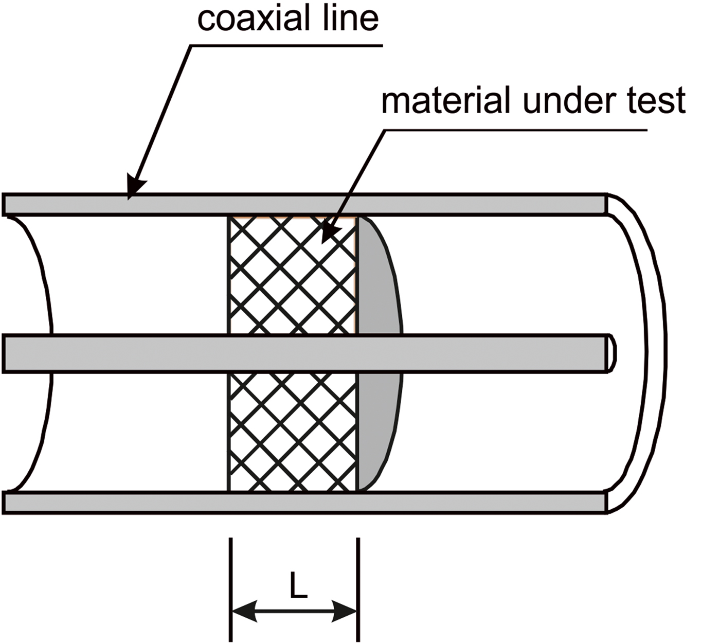
The permittivity and permeability broadband measurements of materials are commonly performed using coaxial fixtures. The basic measurements are based on scattering parameters of the sample. Coaxial line technique allows to measure the constitutive parameters of materials over the wide frequency band. In a typical configuration of a solid material measurement of the permittivity and permeability in a coaxial line, the sample completely fills the cross-section of the holder – Fig. 1. Due to the symmetrical property of the sample, the four S-parameters (S ik) can be simplified to two parameters, e.g. S 11 and S 21, necessary to characterize the material.

Fig. 1. Schematic configuration of the sample in the coaxial line.
The reflection and transmission S-parameters in coaxial line where thetransverse electromagnetic mode is propagated can be interpreted as the infinite series of rays when the incident electromagnetic field is treated as a plane wave. This sum of rays is, in fact, a geometric infinite series yielding to the following formulas of scattering coefficients:
 $$S_{11} = \rho \displaystyle{{1 - e^{ - 2\gamma {\kern 1pt} L}} \over {1 - \rho ^2e^{ - 2\gamma {\kern 1pt} L}}},$$
 $$S_{21} = \displaystyle{{(1 - \rho ^2)e^{ - \gamma {\kern 1pt} L}} \over {1 - \rho ^2e^{ - 2\gamma {\kern 1pt} L}}}.$$
Scattering parameters (3) and (4) are functions of unknown parameters ε and μ of the specimen. The values of complex permittivity and permeability are calculated from S 11 and S 21 according to Nicolson, Ross, and Weir (NRW) formulas [Reference Baker-Jarvis, Janezic, Riddle, Johnj, Kabos, Holloway and Grosvenor7–Reference Weir9]:
 $$\mu = - j\displaystyle{{1 + \rho} \over {1 - \rho}} \displaystyle{\lambda \over {2\pi {\kern 1pt} L}}\ln {\kern 1pt} {\kern 1pt} \left( {\displaystyle{1 \over \gamma}} \right),$$
 $$\varepsilon = - \displaystyle{1 \over \mu} \left[ {\displaystyle{\lambda \over {2\pi {\kern 1pt} L}}\ln {\kern 1pt} {\kern 1pt} \left( {\displaystyle{1 \over \gamma}} \right)} \right]^2,$$
where:
 $$\gamma = \displaystyle{{S_{11} + S_{21} - \rho} \over {1 - \rho (S_{11} + S_{21})}},$$
 $$\rho = X \pm \sqrt {X^2 - 1}, $$
 $$X = \displaystyle{{1 - V1{\kern 1pt} \;\;V2} \over {V1 - V2}},$$
 $$V1 = S_{21} + S_{11}\quad V2 = S_{21} - S_{11},$$
and
λ – wavelength in free space, L – length (thickness) of the sample.
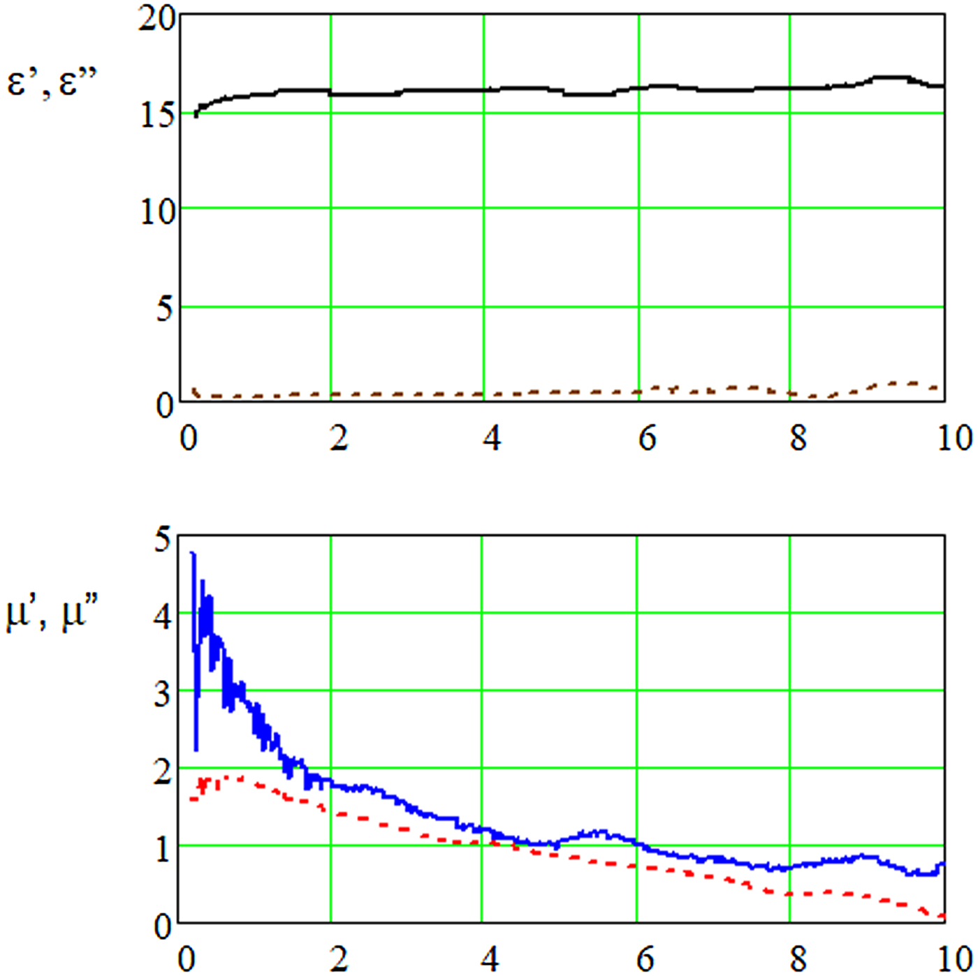
The above equations allow to determine the complex values of permittivity and permeability of the sample in a coaxial line. Measurement of complex relative permittivity and permeability was carried out using a vector network analyzer. This system consisted of a 7 mm coaxial air-line, equipped with measurement cables and LPC7 connectors. The center conductor of the coaxial air-line is 3.04 mm in diameter to ensure that the holder maintains a characteristic impedance of 50 Ω. The system measures the magnitudes and phases of S-parameters of a sample. The obtained data of relative complex permittivity and permeability were presented in Fig. 2. Measurements were carried out in the frequency range from 100 MHz to 10 GHz.

Fig. 2. Electric and magnetic constants (ε′, μ′) – continuous lines and electric and magnetic loss factors (ε″, μ″) – dashed lines, of the composite material in function of frequency.
Shielding effectiveness
The permittivity and permeability values for the material (Fig. 2) obtained in the previous chapter are the constitutive properties of the material, allowing us to assess the shielding effectiveness (SE) for any slab of material i.e. one with an arbitrary thickness (d). The shielding effectiveness is defined as the ratio of the power of the incident wave P I to that of the transmitted wave P T:
 $$SE = {\rm 1}0{\rm log}(P_I/P_T){\rm} [{\rm dB}].$$
Shielding effectiveness determines how much the electromagnetic energy decreases as it propagates through the layer due to reflected and absorbed portion of energy by the material. In fact, shielding effectiveness is nothing but transmission coefficient (S 21).
To characterize the shielding effectiveness of material layer, the typical configuration of the layer in the free space has been presented in Fig. 3.

Fig. 3. Reflection and transmission of the slab of absorbing material.
Shielding effectiveness can be represented by two components: reflection coefficient (SR) and absorption coefficient (SA), according to the following formula:
 $$SE = SR + SA,$$
where:
 $$SR - \hbox{reflection coefficient}$$
 $$SA - \hbox{absorption coefficient}$$
Coefficients mentioned in (12) can be expressed using scattering coefficients. However, it should be noted that at this step of the evaluation, the scattering coefficients refer to the layer thickness of the absorber (d), and will be marked as Sd ik
 $$Sd_{11} = \rho \displaystyle{{1 - e^{ - 2\gamma {\kern 1pt} d}} \over {1 - \rho ^2e^{ - 2\gamma {\kern 1pt} d}}},$$
 $$Sd_{21} = \displaystyle{{(1 - \rho ^2)e^{ - \gamma {\kern 1pt} d}} \over {1 - \rho ^2e^{ - 2\gamma {\kern 1pt} d}}}.$$
Permittivity and permeability, which define the constitutive properties of the material in equations (13) and (14), were determined in the previous chapter.
The two components of SR and SA in formula (12) can be expressed based on the scattering coefficients (Sd ik) as:
 $$SR = - 10 \cdot \log \left[ {1 - {\left \vert {Sd_{11}} \right \vert} ^2} \right],$$
 $$SA = - 10 \cdot \log \left[ {\displaystyle{{{\left \vert {Sd_{21}} \right \vert} ^2} \over {1 - {\left \vert {Sd_{11}} \right \vert} ^2}}} \right].$$
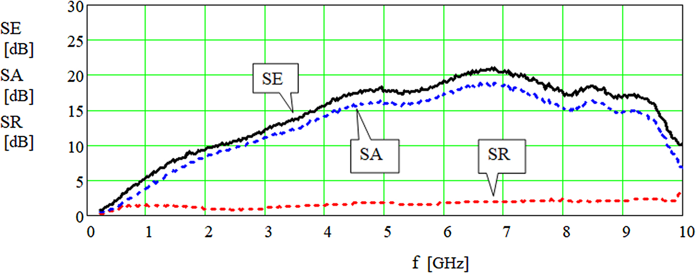
Using the formula (12) it is possible to determine the ratio of energy reflected and absorbed by the material in the total shielding effectiveness. It is obvious that good absorber must have a low value of reflection coefficient and high absorption coefficient. Absorption (SA), reflection (SR) coefficients and total shielding effectiveness (SE) for a slab of the tested absorber of 10 mm of the thickness have been depicted in Fig. 4. Values of all three coefficients expressed in dB have been presented in the frequency range from 100 MHz to 10 GHz.

Fig. 4. Shielding effectiveness SE, reflection coefficient SR, and absorption coefficient SA in function of frequency.
Figure 4 shows that the significant part of the incident energy is absorbed by the material (SA) while the energy reflected from the slab (SR) can be neglected.
Tents or provisional shielding room with walls made out of such a slab absorber fulfill the requirement of free-space because the material shields against external radiation as well as absorbs internal incident electromagnetic radiation. On the other hand, the value of reflected electric field strength is small enough and can be neglected.
Reflection coefficient
The reduction of the radiation reflected from the ground (from the floor) is an important task for EMC measurements. For this reason, the floors of anechoic chambers are covered with ferrite tiles. However, commercially available ferrite tiles are extremely heavy. The weight of 1 m2 of such tiles of thickness of 5.4 mm is about 50 kg. As specified in the technical documentation, the ferrite tiles can be used for frequencies below 1 GHz due to their good shielding effectiveness in this range.
For higher frequencies the absorption properties of ferrite is questioned and, in addition, for frequencies higher than 6 GHz, this material cannot be treated as absorber (it is transparent to the electromagnetic field [Reference Kubacki10]).
To assess the reflection properties of the proposed absorbing material, the configuration of a slab of material on the metal sheet was taken into consideration – see Fig. 5. In this case, metal sheet represents the electric properties of the ground (worst case scenario).

Fig. 5. Reflections from the slab of material on the metal layer.
For the slab of material laying on the conductive metal sheet, the reflection loss coefficient can be expressed as:
 $${\rm RL (dB)} = 20 \cdot \log \left \vert {{\kern 1pt} \Gamma} \right \vert, $$
where Γ is the reflection coefficient, which can be calculated using the following formula [Reference Zhang and Sun11]:
 $$\Gamma = \displaystyle{{\sqrt \mu \cdot \tanh (\alpha ) - \sqrt \varepsilon} \over {\sqrt \mu \cdot \tanh (\alpha ) + \sqrt \varepsilon}}, $$
 $$\alpha = \gamma \cdot d,$$
 $$\gamma = j \cdot 20 \cdot \pi \cdot \displaystyle{1 \over 3} \cdot f \cdot \sqrt {\varepsilon \cdot \mu}. $$
The above equations can be solved with the complex values of permittivity and permeability measured for the tested composite material, as presented in Fig. 2. The calculated reflection loss coefficient has been presented using the following much suitable relationship. This form of relationship is easier to compare with equation (15).
 $${\rm RLF}({\rm dB}) = - 10 \cdot \log \left[ {1 - {\left \vert \Gamma \right \vert} ^2} \right].$$
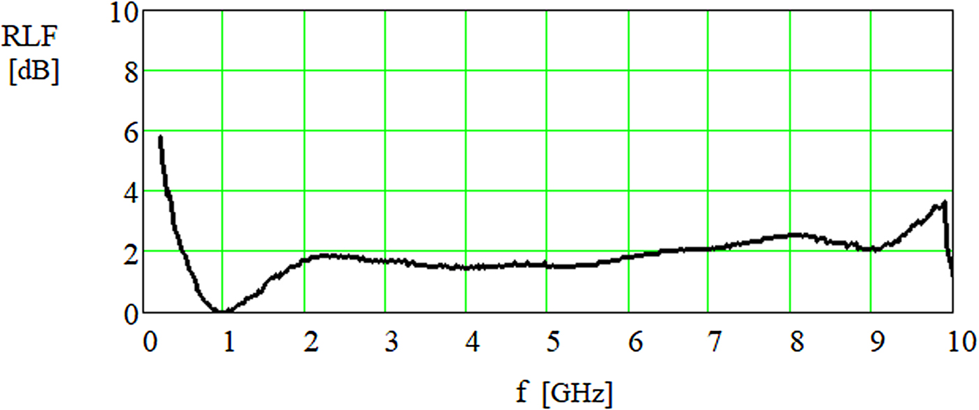
The value of reflection loss coefficient (RLF) for 10 mm thick slab of tested absorber in function of frequency has been presented in Fig. 6.

Fig. 6. Calculation of the RLF of the absorbing material with a thickness of 10 mm backed with the metal layer.
The obtained value of reflection loss coefficient of analyzed absorbing material in function of frequency (Fig. 6) shows that the tested absorber demonstrates attractive reflection properties, in the frequencies from 1 to 9 GHz, because the RLF has low values of about 2 dB. In addition, at a frequency of 1 GHz there is no reflection from this slab of material laying on the metal because the RLF is equal to 0 dB.
Conclusions
The aim of this work was to design the effective absorber which can be used for the open space EMC test. The composite material based on the nanocrystalline-amorphous alloy and graphite was proposed for this purpose. These components were dispersed in an elastomer. The following gravimetric composition has been designed: 70% of nanocrystalline alloy, 1% of graphite, and 29% of the elastomer. The relative complex permittivity and permeability of the proposed composite material have been measured and shielding properties were assessed to analyze the absorption and reflection coefficients of a slab of material as well as for layer backed by a metal sheet. The measurement, performed for the frequency range from 100 MHz to 10 GHz, demonstrates good shielding properties of this absorbing material and its applicability for EMC testing in open space conditions.
Acknowledgment
This work was supported by NCBiR under project No DOB-1-1/1/PS/2014.
 Roman Kubacki received the Ph.D. and D.Sc (habilitation) degrees in electronics from Military University of Technology, Warsaw, Poland in 1991 and 2000, respectively. In 2002 he became an Assistant Professor. Since 2013 he has been the full professor. He was the head of the Microwave Safety Division. Since 2007 he has been with the Military University of Technology, Warsaw, Poland. His research interests include metrology of electromagnetic field, electromagnetic interaction with materials, and the new technology of absorbers. He was also the Chairman of the Polish Radiation Research Society and actually he is the member of the main board of the Polish Society of Applied Electromagnetics.
 Wojciech Głuszewski is a graduate of the Faculty of Chemistry at the Warsaw University of Technology in the specialty of new materials for electronics. At the Institute of Electron Technology in Warsaw, he dealt with photolithography and electroless gold issues. He received the Ph.D. degree in radiation chemistry from Institute of Nuclear Chemistry and Technology in Warsaw (INCT) in 2008. He works at the Centre of Radiation Research and Technology INCT. He is the specialist in the field of radiation chemistry and technology. Currently he is dealing with issues of radiation modification of polymer materials. He is also the specialist in the field of electron and gamma-ray dosimetry. He also deals with the issue of radiation preservation of works of art.
 Dariusz Laskowski received the Ph.D. and D.Sc (habilitation) degrees in electronics from Military University of Technology, Warsaw, Poland in 2005 and 2014 respectively. In 2015 he became an Assistant Professor. His research interests include the multi-faceted analysis of the phenomena determining the correct implementation of services in heterogeneous systems and networks offering data transmission, focusing on reliability, safety, quality and survival of technical objects (e.i. antenna, terminal, switch, transmitter, router) in terms of their practical use in heterogeneous networks.
 Karol Rudyk received M.Sc in electronics from Military University of Technology, Warsaw, Poland in 2014. Currently Ph.D Student. His interests include analog electronic circuits, computer simulation and modeling algorithms and microwave engineering.
 Marek Kuchta received the Ph.D. and D.Sc (habilitation) degrees in electronics from Military University of Technology, Warsaw, Poland in 1988 and 2014 respectively. He is currently holding a position of Senior Lecturer at the Faculty of Electrical Engineering of Military University of Technology in Warsaw. His scientific interests include measurements of electromagnetic field and modeling of human motor system.