Introduction
The fast development of the ultra-wideband (UWB) antennas has been noticed by researches in recent years. According to the Federal Communications Commissions (FCC), UWB antennas operate in the frequency ranges of 3.1–10.6 GHz [Reference Wu and Tarng1].
So far, several methods are used to obtain rejection frequency bands at the operation frequency band of UWB antennas. The author in [Reference Shuai, Wang and Zhou2] had obtained a rejection frequency band by using a slot on the patch. In [Reference ur Rehman and Alkanhal3], curved lines on the ground plane cause rejection bands. Use of two U-shaped gap on the ground plane [Reference Chang, Ding and Weng4], L-shaped slot on the defected ground plane [Reference Srivastava, Kumar, Kumar and Verma5], and hexagonal patch with a hexagonal slot on it [Reference Mandal, Choudhury and Das6] and octagon-shaped patch with a C-shaped slot on the truncated ground plane [Reference Jalil, Chakrabarty and Kasi7] are other techniques used to achieve rejection frequency bands.
On the other hand, advances in microwave semiconductor processing technologies have enabled the use of compact and high-quality radio frequency and microwave switches in novel aspects of antenna design [Reference Nikolaou, Kingsley, Ponchak, Papapolymerou and Tentzeris8–Reference El-Massry, Medhat and Mostafa10]. As known, the switches have different types such as pin diode switches [Reference Shirazi, Li and Gong11–Reference Lu, She and Yan12], optical switches [Reference Okazeri, Muraoka, Shoji, Nakagawa, Nishiyama, Arai and Mizumoto13], capacitive switches [Reference Kula and Lup14], mechanical [Reference Peng, Husain, Huang, Lequesne and Briggs15], and microelectromechanical system (MEMS) switches [Reference Ponchak, Simons and Scardelletti16]. The most important switches in antenna applications are electromechanical MEMS switches which have electrical and mechanical parts. For example, in [Reference Bemani and Nikmehr17], by using MEMS switches, a reconfigurable multi-band antenna is presented.
Fractal antennas have irregular geometry which can be divided into several parts and each one contains more parts. The first fractal is discovered in 1975 by Benoit Mandelbrot. Fractals have a lot of applications in engineering. Fractal antennas are used in array antennas. They have multiband applications. It is possible to achieve compact components by fractal antennas. Designing low-cost antennas is probable by fractal antennas [Reference Lui, Cheng and Zhu18, Reference Bairy, Kumar and Shanmuganantham19].
In this paper, a new UWB microstrip fractal antenna based on the Koch fractal method is introduced. The proposed antenna has two c-shaped slots. Also, 10 MEMS switches in ideal condition are used to create band notch in six frequency bands of 5.2–5.5, 5.7–5.9, 5.9–6.3, 6.9–7.2, 7.7–8.1, and 8.2–8.6 GHz. These frequency bands are in interference with WLAN and WiMAX applications. The organization of this paper is as follows: section “Antenna design” reviews the basic idea of our UWB reconfigurable antenna. Also, in this section, the geometry and operation mechanism of the proposed antenna is described. Section “Results and discussion” demonstrates the validity of the designed antenna through numerical analysis of simulation and experimental results of the fabricated antenna. Finally, the conclusion is given in section “Conclusion”.
Antenna design
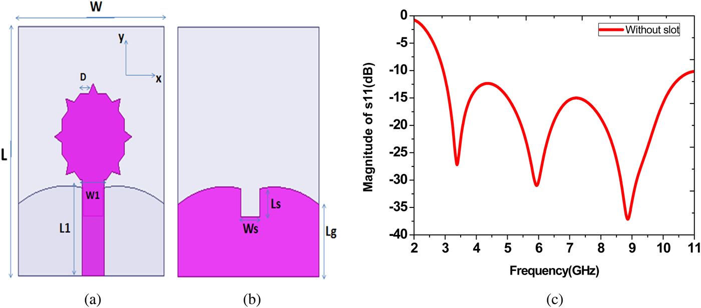
Figure 1. shows the initial structure of the proposed microstrip UWB antenna. In order to increase the bandwidth of the antenna, a defected ground plane is used. Also, in order to reduce the dimensions of the proposed antenna, fractal structure (based on the Koch method) is considered for the patch of the antenna. Figure 1(c) displays the magnitude of S 11 for this antenna without slots.

Fig. 1. (a) Top view. (b) Bottom view. (c) Magnitude of S 11 for the initial structure of the proposed microstrip UWB antenna.
Dimensions of the proposed antenna are: L = 38.40 mm, L1 = 14.76 mm, W = 31.20 mm, D = 1.83 mm, Lg = 11.16, Ls = 4.38, and Ws = 4.08.
Subsequently, two modified C-shaped slots are considered on the patch of the proposed antenna to produce the desired band notches. Figure 2 (a) presents the structure of the proposed antenna with C-shaped slots. As presented in [Reference Chu and Yang20], the notch frequency given in the dimension of the band-notch can be written as
 $$f = \displaystyle{c \over {2L\sqrt {\varepsilon _{{\rm eff}}}}}, $$
where L is the total length of the C-shaped slot, εeff is the effective dielectric constant, and c is the speed of the light. We used this equation to calculate the initial length of a single C-shaped slot at the beginning step of the design. However, the simulations showed that in this stage, the desired frequency notch cannot be achieved. Therefore, in order to achieve the desired frequency notch at WLAN bands, a second mirrored C-shaped slot is chosen and added onto the radiation patch. Finally, the analysis of the notch with different widths and lengths of the slots is performed by HFSS software to get the optimized values. The final values are F = 3.50 mm, G = 9.60 mm, k = 3.60 mm, t = 1.20 mm, z = 4.20 mm.
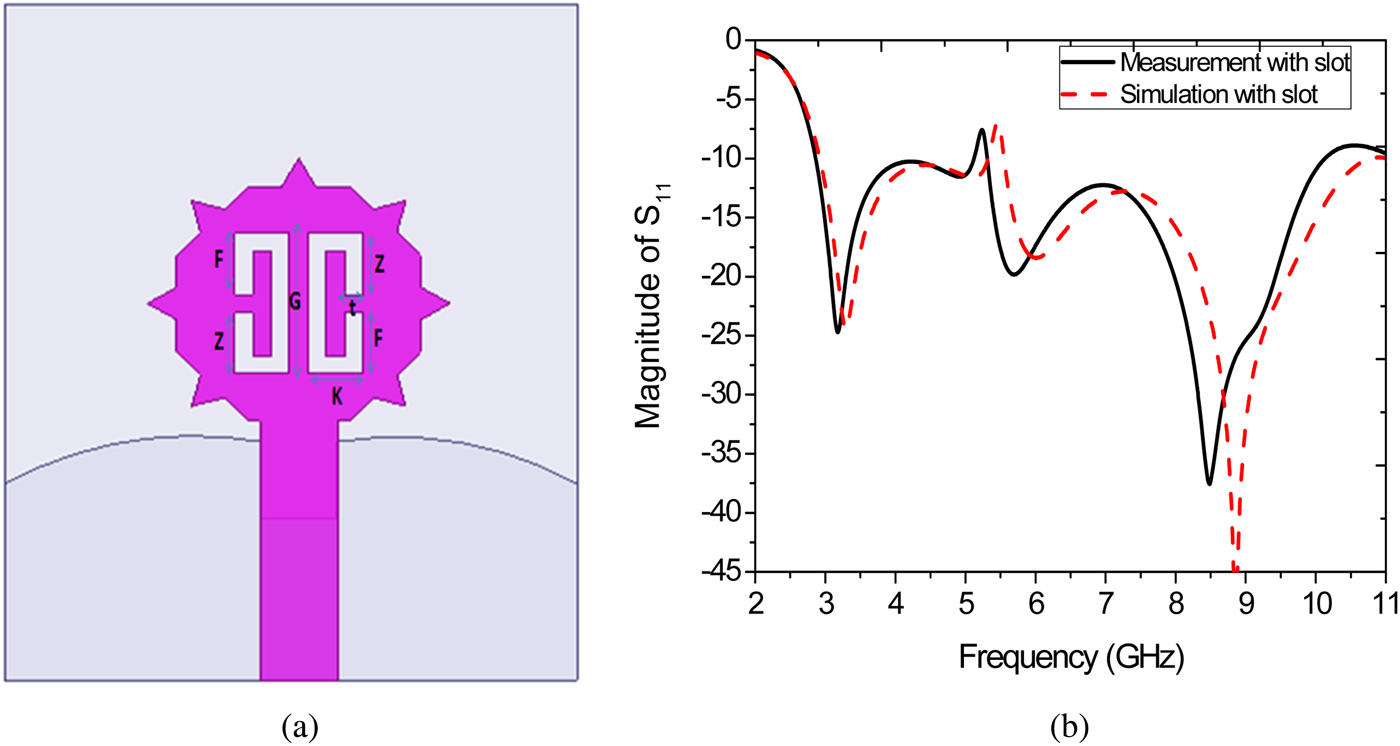
Fig. 2. (a) The antenna structure. (b) Curve magnitude of S 11 of the proposed microstrip UWB antenna with C-shaped slots.
The magnitude of S 11 for this antenna is shown in Fig. 2(b). As can be seen in this figure, by using two slots, a frequency band notch of 5.4 GHz (5.2–5.5) is produced.
Finally, 10 ideal MEMS switches are considered in the C-shaped slots to control the frequency band notches. The final structure of the proposed reconfigurable microstrip fractal UWB antenna is shown in Fig. 3.
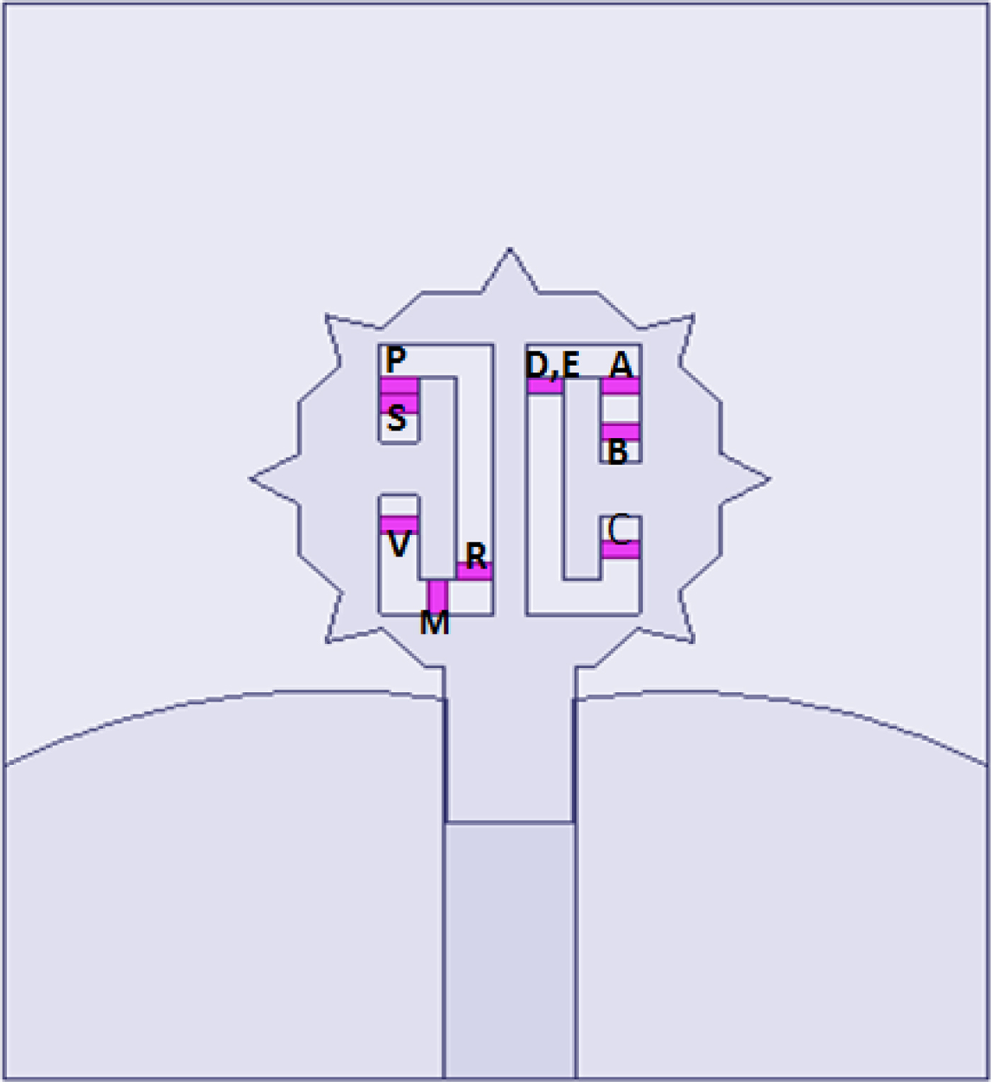
Fig. 3. Final geometry of the proposed reconfigurable microstrip UWB antenna with 10 switches in C-shaped slots.
Results and discussion
The proposed antenna was simulated in HFSS software. Also, as shown in Fig. 4 the designed antenna was fabricated in six states of the switches.
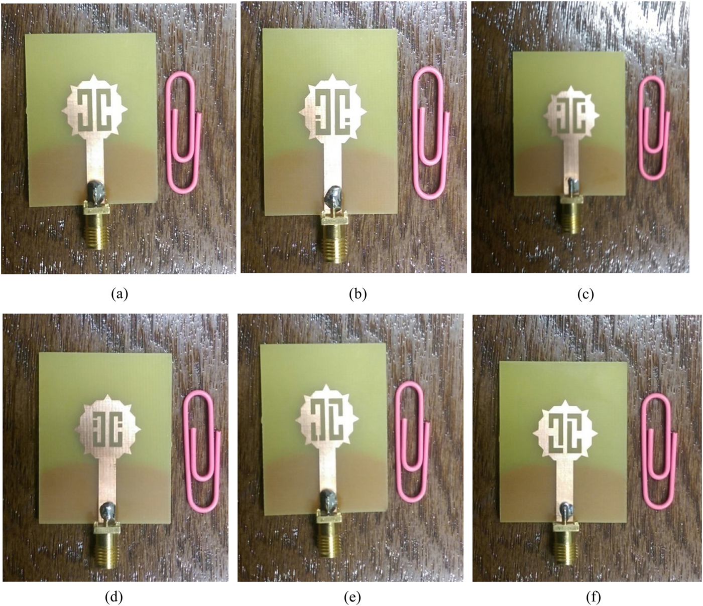
Fig. 4. Photographs of our fabricated reconfigurable antennas in six states. (a) All switches are OFF, (b) state II (V and C are ON), (c) state III (A and P are ON), (d) state IV (S and B are ON), (e) state V (D and M are ON), and (f) state VI (R and E are ON).
Input reflection coefficients of the antenna in various states are exhibited in Fig. 4. As seen in these figures, the results of measurements and simulations are in good agreement. The summarized results of this figure are presented in Table 1.
Table 1. Electrical operation of the proposed reconfigurable microstrip UWB antenna in six states
Figure 5 displays input reflection coefficient of the proposed reconfigurable microstrip UWB antenna. Figures 6(a)–6(i) show the simulated current distribution of the proposed reconfigurable microstrip UWB antenna in frequencies and different states. These figures verify the operation of C-shaped slot and switches in various states.
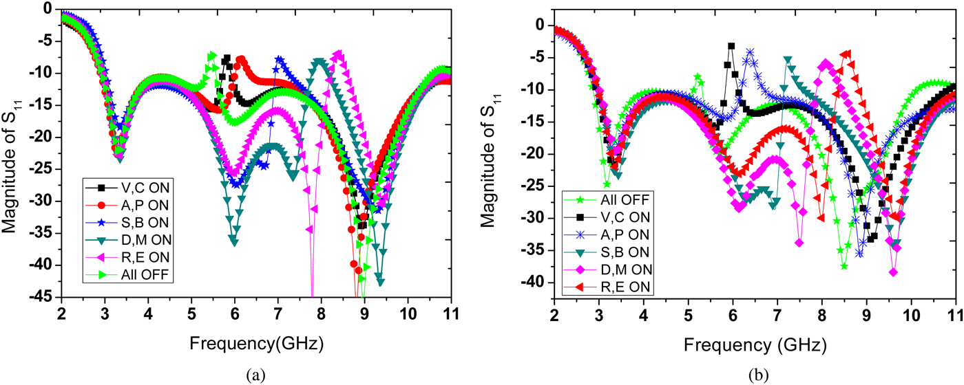
Fig. 5. (a) Simulated and (b) measured input reflection coefficient of the proposed reconfigurable microstrip UWB antenna.
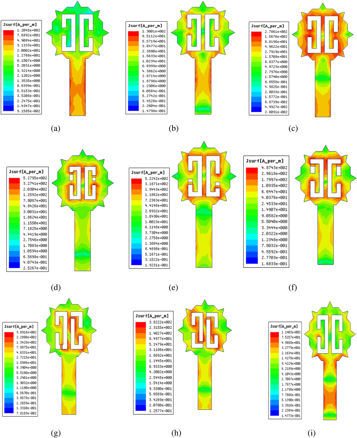
Fig. 6. Simulated current distribution of the proposed reconfigurable microstrip UWB antenna in frequencies of (a) 3.5 GHz, (b) 5.2 GHz, (c) 5.4 GHz (in state I), (d) 5.8 GHz (in state II), (e) 6.1 GHz (in state III), (f) 7 GHz (in state IV), (g) 7.9 GHz (in state V), (h) 8.4 GHz (in state VI), and (i) 9 GHz.
The radiation patterns of the proposed antenna in three frequencies of 3.5, 6.5 (in state I), and 9.5 GHz are shown in Fig. 7. These figures show that the designed antenna has omnidirectional patterns in different frequencies.
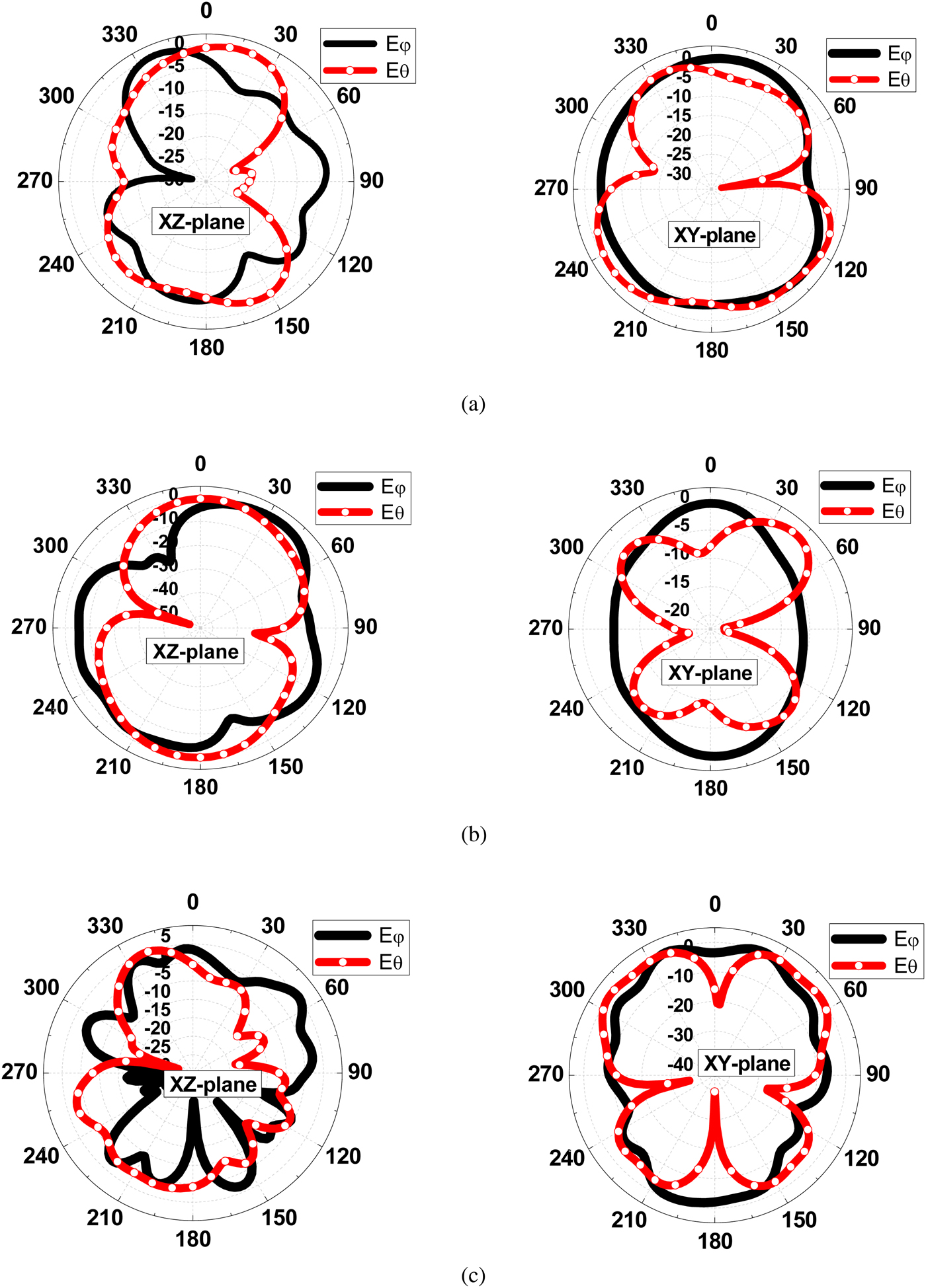
Fig. 7. Radiation patterns of the proposed antenna at (a) 3.5 GHz, (b) 5.2 GHz, and (c) 9 GHz.
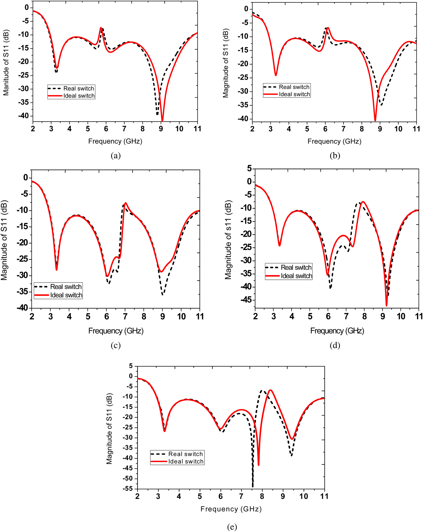
Figure 8 shows the simulated surface current distribution of real MEMS switch in two states close and open, where in close state current is more intense and in open state current is disconnected. Figure 9 presents comparison of the simulated magnitude of S 11 for proposed antenna between the ideal and real models of MEMS switch.

Fig. 8. Simulation model of the RF MEMS switch and surface current distribution on the wire band: (a) close state, (b) open state.

Fig. 9. Comparison of the simulated magnitude of S 11 for proposed antenna between the ideal and real models of MEMS switch. (a) State I (V and C are ON), (b) state II (A and P are ON), (c) state III (S and B are ON), (d) state IV (M and D are ON), (e) state V (R and E are ON).
Conclusion
This paper presented a new reconfigurable microstrip fractal UWB antenna with a capability of variable rejection frequency bands. The proposed fractal antenna with a modified C-shaped slot was designed and fabricated on an inexpensive substrate of FR4. Ten ideal MEMS switches are considered in C-shaped slots in order to produce band-notch frequencies at six different frequency bands of: 5.4 GHz (5.2–5.5), 5.8 GHz (5.7–5.9), 6.1 GHz (5.9–6.3), 7 GHz (6.9–7.2), 7.9 GHz (7.7–8.1), and 8.4 GHz (8.2–8.6). It works in a wide bandwidth of 2.9–11 GHz. The designed antenna has omnidirectional patterns in different frequencies, proper gain through the desired frequency bands and low gain in frequency band notches. Measurement and simulation results are in good agreement.
 Nasrin Nemati received the B.S. degree in electrical engineering from the University Of Roshdiyeh University Of Technology, Tabriz, Iran, in 2016 and the M.S. degree from the University of Tabriz, Tabriz, Iran, in 2018. Her research interests include Ultra wideband antenna with band-notch, reconfigurable antenna, Fractal antennas and Microwave imaging of cancer tumor.
 Mohammad Bemani received the B.S. degree in electrical engineering from KN Toosi University of Technology, Tehran, Iran, in 2007 and the M.S. and Ph.D. degrees, both from the University of Tabriz, Tabriz, Iran,in 2009 and 2014, respectively. He is currently an Assistant Professor in the Department of Electrical and Computer Engineering of University of Tabriz, Iran. His research interests include multi-band and UWB components, reconfigurable antenna, dielectric resonator antennas, composite right and left-handed structures and negative-refractive-index, active circuits and antenna arrays.