


NOMENCLATURE
- a
-
torque offset of the rotor blade
- g
-
acceleration due to gravity (= 9.81 m2/s)
- Ixx, Iyy,
- Izz, Ixz
-
aircraft mass moments of inertia about body axes at the c.g
- H, Y, T
-
x-, y-, z-components of hub forces, respectively
- L, M, N
-
components of total moments along body axes at the c.g
- m
-
mass of the helicopter, kg
- pf, qf, rf
-
angular velocities along body axes at the c.g
- Vf
-
helicopter velocity
- v, w
-
lag and flap response of rotor blade
- uf, vf, wf
-
velocity components along body axes at the c.g
- X, Y, Z
-
components of the total forces along body axes at the c.g
- β
-
sideslip angle (= sin–1(vg/Vf))
- βd
-
pre-droop angle of rotor blade
- βp
-
pre-cone angle of rotor blade
- βs
-
pre-sweep angle of rotor blade
- γf
-
flight path angle
- θ0
-
main rotor collective
- θ0t
-
tail rotor collective
- θ1C
-
lateral cyclic
- θ1S
-
longitudinal cyclic
- μ
-
advance ratio
- ρ
-
density of the blade, kg/m3
- χe
-
track angle
- Θ
-
fuselage pitch attitude
- Λa
-
tip anhedral angle
- Λs
-
tip-sweep angle
- Φ
-
fuselage roll attitude
- Ψ
-
rotor blade azimuth angle
- Ω
-
rotational speed of the rotor blade, rpm
- Ωa
-
turn rate of vehicle, rad/s
1.0 INTRODUCTION
Determination of airload distribution on the rotor is a basic necessity for an improved design of rotorcraft. The designer is usually concerned with the periodic loads occurring in steady-state straight or maneuvering flight. The periodic aerodynamic environment of the helicopter rotor produces high oscillatory loads in the blades, hub and control system. Oscillatory loads are a major factor in rotor design as they cause vibration and fatigue in the helicopter. Hence, a major design goal in helicopters is to reduce the oscillatory loads on the rotor while improving performance.
For performance improvement and noise reduction, new generations of advanced-geometry rotor blades have incorporated swept and anhedral tips(Reference Yen1). Swept tips are usually introduced in rotor blades to delay compressibility effects, to reduce Mach tuck and to improve performance in general. Likewise, tip anhedral is introduced to prevent tip vortex-blade interaction resulting in a more uniform angle-of-attack distribution and hence better performance. While there are aerodynamic benefits to these advanced tip geometries, they come at the cost of complicated structural design and weight penalties. The effect of these tip shapes on loads, vibration and aeroelastic response are also unclear. Hence, it has become necessary to study the effects of these advanced geometry blades on the aeroelastic behaviour of the rotor system. Swept and anhedral tips influence blade dynamics because they are located at regions of high dynamic pressure and relatively large elastic displacements. Rotor blades with sweep and anhedral at the blade-tip region experience bending torsion and bending-axial coupling effects in addition to those already present in conventional geometry blades. Aeroelastic analyses of advanced geometry blades with tip sweep and anhedral can be found in Refs Reference Celi and Friedmann2–Reference Bernardini, Piccione, Anobile, Serafini and Gennaretti4. Studies of composite rotor blades with advanced geometry can be found in Refs Reference Yuan, Friedmann and Venkatesan5–Reference Epps and Chandra7. These analyses have included Panda's(Reference Panda8) general nonlinear transformation and constraint relations at the junction between two blade elements joined at an angle to each other. These transformations have included nonlinearities which were found to be important, especially for large sweep angles.
The complexity of the helicopter aeroelastic problem requires the development of a comprehensive analysis program that integrates all the disciplines involved in the study(Reference Johnson9). In this paper, one such comprehensive helicopter aeroelastic analysis which includes rotor-fuselage coupling shall be described and validated, and results of analyses for rotor blades with straight tip, tip sweep and tip anhedral are compared. The effects of tip sweep and tip anhedral on structural dynamics, trim characteristics and vehicle response to pilot inputs are presented. The work done in this study is an extension and improvement of the comprehensive aeroelastic analysis developed in Ref. Reference Laxman and Venkatesan10 for a helicopter with straight blades in forward flight condition.
2.0 MODELLING
2.1 Blade structural model
The structural and the aerodynamics models used in the helicopter aeroelastic analysis have been described in Refs Reference Kumar and Venkatesan11 and Reference Kumar and Venkatesan12. Hence, only a brief outline is given here. For the structural model, an elastic rotating beam with constant angular velocity Ω was considered. Blade sweep, precone, predroop, pretwist, root offset and torque offset are included in the model (Fig. 1). The beam consists of a straight portion and a tip with sweep and anhedral angles relative to the straight portion. By convention, backward sweep and upward dihedral angles have been taken as positive. The cross section of the blade has a general shape with distinct shear centre and centre of mass.

Figure 1. Blade coordinate systems (side and top views).
The nonlinear equations of motion and the corresponding finite element matrices were derived for each beam element using Hamilton's principle. The blade was modelled by a series of straight-beam finite elements along the elastic axis of the blade. Two finite elements at the tip were used to model the sweep and anhedral. Each finite element in the tip can be given a sweep angle and/or anhedral angle independent of the other. Each beam element consists of two end nodes and one internal node at its mid-point, resulting in 14 degrees of freedom representing four lag, four flap, three torsional and three axial deformations. Cubic Hermite interpolation polynomials are used for the bending displacement, while quadratic Lagrangian interpolation polynomials are used for torsional rotation and axial deflections.
2.2 Aerodynamic model
The aerodynamic model involves the evaluation of inflow at various locations on the rotor disc and the evaluation of sectional aerodynamic loads on the rotor blade. While the comprehensive analysis program has been implemented as modular with multiple options for inflow and load calculations, for the purpose of this paper, only the Peters-He dynamic wake model(Reference Peters and He13) for inflow and the ONERA dynamic stall model(Reference Petot14) for loads are discussed. Both these models, by virtue of being formulated as a set of differential equations, are very suitable for aeroelastic calculations. In the unstalled region, the ONERA model is identical to Theodorsen's unsteady aerodynamic theory except that the lift deficiency function C(k) is approximated by a first-order rational approximation. The study in Ref. Reference Laxman and Venkatesan15 concluded that replacing the first-order rational approximation by a second-order approximation results in a more accurate modified ONERA dynamic stall model, which shall be used in the present analysis.
The aerodynamic calculations are performed in the following manner: (1) The oncoming flow velocity at a section and the rotor inflow (acting perpendicular to the hub plane) are first projected along the local coordinate system (eK) of that section. (2) The sectional loads are then calculated along this local coordinate system. (3) The loads are then transferred to 4K system which coincides with the local coordinate system for the straight portion of the blade. The transformation between the local (eK) and the 4K systems takes into consideration any sweep or anhedral angle at the section.
2.3 Flight dynamics
A most general steady maneuver in spin mode is depicted in Fig. 2. The spin axis is always directed vertically. The non-linear algebraic trim equations, the equations of motion for the six fuselage degrees of freedom and the kinematic equations used are based on the formulations in Ref. Reference Padfield16.

Figure 2. Helicopter in a general manoeuver.
3.0 SOLUTION PROCEDURE
The complete solution procedure including the aeroelastic equation and the flowchart have been given in Ref. Reference Kumar and Venkatesan11. For structural dynamics, the rotor blade was modelled using finite elements, with each element having 14 degrees of freedom. Modal coordinate transformation was used to reduce the total number of degrees of freedom. Eight modes comprising two lag, four flap, one torsion and one axial modes were used in the modal transformation.
The trim algorithm consists of two iterative loops, an inner loop and an outer loop. In the inner loop, the blade equations and the aerodynamic equations are evaluated at alternate time steps for a whole revolution. These are iterated until convergence. Once the inner loop converges, the trim equations are solved in the outer loop. The outer loop is also iterated until convergence. The aerodynamic loads were calculated at 15 equidistant stations on the rotor blades. The analysis was implemented as a C++ program using the open-source GSL(17) as the math library. The blade and aerodynamic differential equations were solved using the Runge-Kutta method while the non-linear algebraic trim equations are solved using the Newton-Raphson method.
The control response is determined by integrating the full set of non-linear equations of motion with respect to time after evaluating the blade and hub loads at every time step. In this study, the helicopter flying in level, forward trim condition is subjected to a step input in the lateral cyclic and longitudinal cyclic angle, one at a time, for five seconds. The response of the helicopter to these disturbances is studied in terms of its translational and angular velocities.
4.0 VALIDATION
The structural dynamics formulation was validated(Reference Kumar and Venkatesan11) with the University of Maryland vacuum chamber experiments(Reference Epps and Chandra7) and was also compared with RCAS results for the same set of experimental data(Reference Hopkins and Ormiston18). The aeroelastic formulation was also validated in Ref. Reference Kumar and Venkatesan11 with flight test data for steady, level, forward flight trim angles. Important results from these studies are reproduced here. The vehicle and blade properties are given in Table 1. The rotor of the helicopter turns anticlockwise when viewed from the top.
Table 1 Vehicle and blade properties

On examining the azimuthal variation of the sectional loads of the rotor blade near the tip at high speeds (not plotted here), it was observed that the minimum for the sectional lift at 0.95 R is at the end of the first quadrant. Similarly, the sectional pitching moment near the tip was found to have a minimum at the end of the second quadrant. From literature study, it was learnt that similar observations have been made for other helicopter rotors under similar non-dimensional conditions. In the absence of test data for the helicopter used in the present study, test data from a research Puma and a UH-60A available in Refs Reference Bousman19 and Reference Yeo and Johnson20 are used for comparison with the tip sectional lift and tip sectional moment of the current analysis as shown in Fig. 3. It is to be noted, however, that a one-to-one comparison is not appropriate since there are many structural and aerodynamic differences between the rotors of the two referred helicopters and the helicopter data used in the present study. The sectional lift and the sectional pitching moments at the tip of the current analysis qualitatively resemble the tip sectional lift and pitching moment curves of the research Puma and the UH-60A in high-speed flight.

Figure 3. Qualitative comparison of forces and moments (Refs Reference Bousman19 and Reference Yeo and Johnson20).
5.0 RESULTS
Results pertaining to the influence of tip sweep and tip anhedral on rotor structural dynamics, helicopter trim and control response are discussed here. Sweep or anhedral is given over the outer 10% of the overall span of the rotor blade. The blades have the same property in every other aspect. Results of two tip sweep cases (15° and 30°) and two tip anhedral/dihedral cases (–10° and 10°) are compared with those of the straight blade case. It is to be noted that tip anhedral is denoted by negative angle and tip dihedral by positive angle.
5.1 Effect of swept tip
It is well known that tip sweep affects the torsion and higher bending modes. It is also known that tip sweep introduces torsion-bending in the rotor blade. The torsion component of the modes increases with increase in tip sweep. These results can also be seen in Ref. Reference Kumar and Venkatesan21.
Tip sweep influences the aerodynamic and structural forces acting on the blade. These, in turn, influence the pilot control settings for trim. Figure 4 shows the variation of trim angles with forward speed for different tip-sweep angles. It is seen that when compared to the straight-blade case, the main rotor collective angles required to trim the vehicle decreases with increase in tip-sweep angle. The lateral and the longitudinal cyclic angles decrease slightly with increase in tip sweep. The reason for this, as will be seen later, is the reduction in the torsion experienced by the rotor blade with tip sweep as compared to the straight blade. The tail rotor collective angles show hardly any change with change in tip sweep. Similarly, the pitch and roll attitudes of the vehicle do not show any variation with change in tip sweep.

Figure 4. Effect of tip sweep on trim variables.
Figure 5 shows the variation of the mean and 1/rev elastic twist at 0.70 R with forward speed. Data for the straight blade is represented by the line with a star symbol, while those of blades with 15° and 30° tip sweeps are represented by lines with filled-circle symbol and hollow-circle symbol, respectively. This is the convention followed for the next few figures. It is seen from Fig. 5 that there is a clear reduction in the amplitude of the mean with increase in tip sweep. This reduction in the steady elastic twist results in a reduced main rotor collective requirement in trim as was seen in the previous figure. This aspect of reduction in main rotor collective with tip sweep has also been observed in Ref. Reference Yen1. Figure 6 shows the effect of tip sweep on the blade response at 0.70 R with time (azimuth) for a forward speed of μ = 0.30. While the flap response increases very slightly with tip sweep, there is a clear reduction in lag with increase in tip sweep. The elastic twist or torsion reduces both in mean value and the amplitude with increase in tip sweep. Harmonic content of the torsion response is seen to increase with increase in tip sweep. The elastic twist is also seen to reduce in the advancing side of the rotor.

Figure 5. Blade elastic twist at 0.70 R.

Figure 6. Tip response at 0.70 R for μ = 0.30.
Next, the loads on the helicopter rotor blade with varying tip sweeps are plotted for a forward speed of μ = 0.30. The loads are expected to be affected by the change in local velocity normal to the blade at the tip due to the introduction of sweep. Another factor affecting the loads is the offset of the aerodynamic centre from the elastic axis. Lift, drag and the torsional moment are given about the elastic axis of the straight portion of the blade. For the inboard sections, there is only a slight effect of tip sweep on the sectional loads, mostly in the advancing side (not shown here). Figure 7 shows the effect of tip sweep on sectional lift, drag and torsional moment for an outboard section (0.95 R). The effect of tip sweep is seen less on the sectional lift and drag and mostly on the sectional pitching moment (Fig. 7c). At 0.95 R, there is a drastic reduction in the pitching moment with increase in tip sweep. The reduction in pitch-down moment is consistent with the reduction in elastic twist as seen in Figs. 5 and 6.

Figure 7. Sectional loads at 0.95 R at μ = 0.30.
Figure 8 shows the effect of tip sweep on the blade root loads in terms of mean and harmonic components. The force components are in the left column and the moment components in the right column. In general, the plots show a reduction in the harmonic content of the root shear force components (Fx, Fy, Fz) with increase in tip sweep. However, there is a slight increase in the higher harmonic content of Fz. Similarly, there is a reduction in the harmonic content of the root moments (Mx, My, Mz) with introduction of tip sweep; however, the root flap moment, My, shows a slight increase in the harmonic content. The mean amplitude of root torsional moment (pitch-down), Mx, increases with increase in tip sweep (Fig. 8b), thereby, causing an increase in the pitch-link loads.

Figure 8. Root forces and moments at μ = 0.30.
Figure 9 shows the effect of tip sweep on the hub loads in terms of mean and harmonic components. The force components are on the left side while the moment components are on the right side. The general trend (except for My and the shaft torque, Mz) is an increase in the 4/rev harmonic of the force and moment components. This indicates an increase in the vibrations transferred to the fuselage.

Figure 9. Hub forces and moments at μ = 0.30.
5.2 Effect of tip anhedral
It is known that the effect of tip anhedral/dihedral is mostly seen in the axial mode whose frequency increases with the introduction of tip anhedral/dihedral. It is also known that tip anhedral/dihedral introduces torsion-bending coupling in the rotor blade. The torsion component of the bending modes for tip anhedral and tip dihedral are of opposite signs. These conclusions can also be inferred from Ref. Reference Bousman19.
Like tip sweep, tip anhedral/dihedral also influence the aerodynamic and structural forces acting on the blade resulting in a change to the pilot control settings for trim. Figure 10 shows the variation of trim angles with forward speed for tip-anhedral/dihedral angles. It is seen that when compared to the straight-blade case, the main rotor collective angles required to trim the vehicle slightly increase for both tip-anhedral and tip-dihedral cases. In the case of tip anhedral/dihedral, there is a loss of lift component in the vertical direction. To compensate for this loss of lift, the collective pitch requirement has increased. The tail rotor collective angle hardly shows any change with change in tip anhedral/dihedral. The lateral cyclic decreases for the tip-anhedral case and increases for the tip-dihedral case. Tip anhedral and tip dihedral introduce opposite variations in the angle-of-attack in the front and aft regions of the rotor. This is the reason for their opposite effects on the lateral cyclic. The longitudinal cyclic angle shows a slight decrease with increase in tip dihedral. With tip anhedral, the longitudinal cyclic is almost the same as the straight blade. The pitch attitude shows a slight additional pitch-down at higher speeds for tip anhedral as well as tip dihedral. The vehicle rolls slightly more to the port side with introduction of tip anhedral/dihedral.

Figure 10. Effect of tip anhedral/dihedral on trim variables.
Figure 11 shows the variation of the mean and 1/rev elastic twist at 0.70 R with forward speed. Data for the straight blade is represented by the line with a star symbol, while those of blades with –10° tip anhedral and 10° tip dihedral are represented by lines with filled-circle symbols and hollow-circle symbols, respectively. This is the convention followed for the next few figures. It is seen from Fig. 11 that there is a small reduction in the amplitude of the mean for both tip anhedral and tip dihedral cases. This reduction in the steady elastic twist is in contrast to the increase in main rotor collective requirement in trim as was seen in the previous figure. Figure 12 shows the effect of tip anhedral/dihedral on the blade response at 0.70 R with time (azimuth) for a forward speed of μ = 0.30.
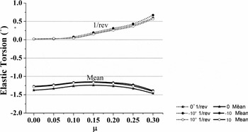
Figure 11. Blade elastic twist at 0.70 R.

Figure 12. Tip response at 0.70 R for μ = 0.30.
The flap response decreases with the introduction of tip anhedral/dihedral. This could be attributed to centrifugal stiffening. The peak-to-peak lag amplitude is seen to reduce with addition of tip anhedral/dihedral. The mean amplitude of torsion reduces when tip anhedral/dihedral is introduced.
Next, the loads on the helicopter rotor blade with varying tip anhedral are plotted for a forward speed of μ = 0.30. The loads are expected to be affected by the offset of the centre of gravity near the tip. The effect of tip anhedral/dihedral on sectional lift, drag and torsional moment is mostly seen in the outboard section (Fig. 13). The results of the inboard sections can be seen in Ref. Reference Bousman19. The peak-to-peak amplitude of the sectional lift is seen to increase for rotor blade with tip anhedral/dihedral. In the case of sectional drag, the outboard section (0.95 R) experiences a drastic increase in drag, especially on the retreating side. Regarding sectional pitching moment, the peak-to-peak amplitude of the pitching moment is decreased in the case of tip anhedral and increased in the case of tip-dihedral.

Figure 13. Sectional loads at 0.95 R at μ = 0.30.
Comparing Fig. 13 with Fig. 7, it is seen that tip anhedral/dihedral tend to affect the loads more than tip sweep, especially in the outboard sections. An interesting observation in Fig. 13 is that at 0.95 R, the sectional lift and drag at azimuth locations 90° and 270° are not affected by tip anhedral/dihedral. In the case of sectional pitching moments, these ‘invariant’ points are around 65° and 210°.
Figure 14 shows the effect of tip anhedral/dihedral on the blade root loads in terms of mean and harmonic components. The force components are in the left column and the moment components are in the right column. In general, the plots show a reduction in the 1/rev harmonics of the root shear force and bending moment. There are slight increases in the higher harmonics of Fz and My. The mean amplitude of root torsional moment (pitch-down), Mx, increases with introduction of tip anhedral (Fig. 14b), thereby indicating an increase in the pitch-link loads.

Figure 14. Root forces and moments at μ = 0.30.
Figure 15 shows the effect of tip anhedral/dihedral on the hub loads in terms of mean and harmonic components. The force components are on the left side while the moment components are on the right side. The general trend observed is that the addition of tip anhedral/dihedral causes an increase in the 4/rev harmonic of the hub loads. This means that the vibratory loads transferred to the fuselage from the rotor is higher for blades with tip anhedral/dihedral than for straight blades.

Figure 15. Hub forces and moments at μ = 0.30.
5.3 Control response
Next, helicopter flight behaviour following pilot control inputs is analysed. Detailed knowledge of the control response is essential for determining the flying qualities of a helicopter. In this section, the effects of addition of blade tip sweep and tip anhedral/dihedral on the rotor control response are studied.
From analysis, the effects of rotor blade tip sweep and tip anhedral/dihedral on the control response in hover and low-speed forward flight regimes were found to be negligible. The results for a high-speed forward flight case are presented here.
Figure 16 shows the helicopter translational and angular velocity responses to a lateral cyclic step-input for μ = 0.30. Figure 16a shows the control response for rotor with straight blades. At μ = 0.30, the pitch attitude of the helicopter is about –1° and the roll attitude is about –2.5°. Among the translational velocity components, only the y-axis component changes in the first couple of seconds. It increases in the positive direction. Among the angular velocity components, the roll rate reaches a value of about –10°/s in about 0.3 seconds (inset) and rises to about –40°/s by 2.5 seconds. From Fig. 16b which is the case of rotor blade with 30° tip sweep, it is seen that there is hardly any effect of sweep on the control response. In case of blade with tip anhedral (–10°, Fig. 16c), it is seen that till about 2.5 seconds, the response is similar to the straight blade case. Beyond 2.5 seconds, the z-component of velocity, the pitch and roll rates all experience a change in direction from their values in the straight blade case. Figure 16d shows the control response in the case of rotor blade with tip-dihedral (10°). The y-and z-components of the body velocity and the pitch and yaw rates show opposite trend as compared to the tip anhedral case. Thus, at high forward speed, the lateral cyclic response is seen to be affected by tip anhedral/dihedral but not by tip sweep.

Figure 16. Variation of translational and angular velocities for lateral cyclic step input at μ=0.30.
Figure 17 shows the response due a longitudinal cyclic step-input. From Fig. 17a (straight blade) and Fig. 17b (30° tip sweep), it is seen that there is only a slight effect of tip sweep on the control response. Between the tip anhedral (Fig. 17c) and tip dihedral (Fig. 17d) cases, the tip dihedral has the most effect on the control response. In this case, the directions of the roll and yaw rates are changed from those of the straight blade case.

Figure 17. Variation of translational and angular velocities for longitudinal cyclic step-input at μ= 0.30.
6.0 CONCLUDING REMARKS
A comprehensive helicopter aeroelastic analysis which includes rotor-fuselage coupling has been formulated and validated for structural dynamics and trim. The effects of tip sweep and tip anhedral/dihedral on structural dynamics, trim and control response of the helicopter were studied. The main observations are:
-
1. From structural dynamic analysis, it is seen that the effect of tip sweep is mostly seen in the torsion and higher bending (flap and lag) modes. The torsion component of the bending modes (flap-torsion coupling) increases with increase in tip sweep.
-
2. Tip sweep reduces the main rotor collective angle requirement for trim in steady, level, forward flight due to the reduction in nose-down elastic twist.
-
3. Tip sweep increases the root torsional moment and thereby increases the pitch-link loads.
-
4. The 1/rev harmonics of the blade root loads reduce due to tip sweep while the 4/rev harmonics of the hub loads show an increase with inclusion of tip sweep. This indicates an increase in the vibratory content of the loads transferred to the fuselage.
-
5. The tip anhedral/dihedral effect is mostly seen in the axial mode. Like tip sweep, tip anhedral/dihedral also introduce torsion component to the bending modes (lag-torsion coupling). Axial-torsion and axial-bending coupling are also introduced because of tip anhedral/dihedral.
-
6. Tip anhedral and tip dihedral have opposite effects on the required lateral cyclic in trim.
-
7. Tip anhedral/dihedral have a larger effect on the sectional loads than tip sweep, especially in the outboard region.
-
8. As in the case of tip sweep, 1/rev harmonics of blade root loads show a reduction while the 4/rev harmonics of hub loads are increased due to tip anhedral/dihedral.
-
9. Lateral cyclic control response at high speeds in forward flight is affected by tip anhedral/dihedral but not by tip sweep.
-
10. Tip dihedral induces a reversal in the yaw rates for both lateral and longitudinal cyclic input as compared to the straight blade.
ACKNOWLEDGEMENTS
The authors thank Hindustan Aeronautics Limited, Bangalore, India for funding this research work. Note: This work was presented at the Fifth Decennial AHS Aeromechanics Specialists’ Conference (San Francisco, California, US, 22–24 January 2014).


