


Introduction
Over the past few decades, circularly polarized (CP) antenna has attracted a lot of interests due to its wide applications in satellite communication system, radio frequency identification (RFID), wireless sensors, and so on [Reference Gao, Luo and Zhu1]. Generally speaking, CP antenna mainly includes two categories, single-feed and dual/multi-feed. The latter one always requires power divider or complicated feeding network, which is not beneficial to design and manufacture. Hence, several attentions have been focused on single-feed CP antenna, which can be easily miniaturized and integrated. Many technologies have been applied to achieve CP radiation, such as varies shaped patch [Reference Chen and Wong2], short pins [Reference Wong, So, Ng, Lug, Chan and Xue3], and cross slotted patch [Reference Chen and Qing4]. However, one drawback of the former one is its narrow impedance matching bandwidth (BW) and axial ratio (AR) BW due to high value of quality factor Q.
In order to broaden its BW, several techniques have been proposed, such as thick air substrate [Reference Yang, Lee, Kishk and Luk5], slot loading [Reference Su, Chang and Wong6], stacked patches [Reference Oraizi and Pazoki7]. However, these designs are always bulky and low radiation efficiency, which are not practical to achieve compact size and high efficiency. To overcome these drawbacks, many novel types of antenna are reported, especially metamaterial-based or metasurface-based structures. In [Reference Zhao, Jiao, Zhang and Yang8], a partially reflective surface (PRS) and artificial impedance surface-based resonant cavity structure was applied to improve radiation gain of CP antenna. Besides, metamaterial-based CP antenna with linearly polarized (LP) wave has attracted much attention [Reference Orr, Goussetis and Fusco9–Reference Zhu, Cheung, Chung and Yuk11], which can simplify the design procedure of CP radiator source. For example, metamaterial-based PRSs have been used to design high gain CP Fabry–Perot cavity antenna [Reference Orr, Goussetis and Fusco9, Reference Liu and Wei-Bing10]. However, most of these designs require a distance between radiator and PRS to satisfy cavity resonance condition. Therefore, some CP antennas with metamaterials under the radiator have been proposed [Reference Yang and Rahmat-Samii12, Reference Yang, Tam, Choi, Che and Hui13]. Yang et al. [Reference Yang, Tam, Choi, Che and Hui13] proposed a low-profile CP antenna with a height of 0.04 λ 0 using a polarization rotating reflective surface based on artificial magnetic conductor, while it is still a challenging problem to obtain wider BW.
Recently, another method by integrating metasurface into a traditional LP aperture antenna was proposed to enhance BW and reduce volume [Reference Liu, Chen and Qing14–Reference Jia, Liu and Gong20]. Liu et al. [Reference Liu, Chen and Qing14, Reference Liu, Chen and Qing15] proposed low-profile broadband mushroom-based and grid slotted metamaterial-based planar antennas by exciting two modes simultaneously. Then, some designs of feeding structure are used to achieve CP radiation based on the two designs [Reference Lin, Chen, Liu and Chen16]. In [Reference Lin, Chen, Liu and Chen16], a low-profile grid-slotted CP patch antenna achieves wide impedance BW and 3 dB AR BW using Z-shaped slotted ground. Another method to obtain circular polarization is using CP metamaterial units array, such as corner truncated patches [Reference Zhu, Cheung, Liu and Yuk17, Reference Sali and Paul18, Reference Huang, Yang, Li, Wang and Wen21]. Different polarization states and radiation patterns are realized owning to some perturbation segments of the truncated corner. However, the wide AR BW of the design is still a challenge. Specifically, with the development of satellite and wireless communication systems, the demands on the antenna are required higher and higher. The antenna design to satisfy these requirements, such as wide operating BW, compact volume and miniaturized size, is a valuable research.
In this paper, a low-profile slot antenna based on metasurface for C-band satellite communication is proposed and studied. The period size of the metasurface is 0.18 λ 0 at center frequency, which shows advantages for miniaturized design. The proposed antenna consists of 4 × 4 unit cells printed on top substrate without air gap, which indicate its superiority for reducing total volume. Besides, compared with published literatures, the mechanism of the metasurface-based antenna is detailed and analyzed based on mode analysis, surface current distributions, and equivalent circuit transmission mode, respectively. The measurements are also given in detail. Further study of parameters reveals key impacts of the antenna and provides design guidelines. Full-wave simulations using commercial software ANSYS HFSS and experimental measurements are carried out to verify the previous analysis and radiation performances of the antenna.
Design and analysis of antenna
Design and full-wave simulation
The proposed antenna geometry is shown in Fig. 1, which consists of three layers. The two layers of dielectric substrates are Arlon AD350A [22] (a dielectric constant εr = 3.5, and a loss tangent tanδ = 0.003) with thickness of h 1 = 0.5 mm and h 2 = 3 mm, respectively. There is no air gap between two substrates, so the volume of the antenna is reduced. The top metasurface with 4 × 4 corner truncated square patches is printed on upper substrate. The lower substrate is sandwiched between middle slotted ground plane and bottom SMA connector and feeding line, which works as a conventional slot antenna. Optimizing parameters of the feeding structure and the truncated corner using commercial software ANSYS HFSS versus 13.0, wide impedance BW and CP BW is realized. The parameters are optimized as follows: p = 9.7 mm, a = 9.2 mm, b = 3 mm, l g = 38.8 mm, l s = 27 mm, w s = 2 mm, l f = 26.4 mm, w f = 1.2 mm, l g = 14 mm, w g = 6 mm, g f = 0.7 mm.

Fig. 1. (a) Schematic view. (b) Front view of top, middle, and bottom structures of the proposed antenna.
To illustrate why CP radiation can be achieved by the proposed metasurface-based antenna, we make comparisons between two slot antennas, as presented in Fig. 2. Ant I is a traditional slot antenna and consists of a ground plane with air slot, feeding line, and two dielectric substrates, as shown in Fig. 2(a). Ant II is a square metasurface-based slot antenna, which is comprised of 4 × 4 square patches printed on upper substrate and the other components are the same as Ant I, as shown in Fig. 2(b). It should be noticed that the parameters of the three antennas are chosen as the same for a fair comparison, such as feeding structure, thickness of two substrates, and period of metasurface and so on.

Fig. 2. Schematic view of (a) Ant I and (b) Ant II.
Figure 3 presents simulated S 11 and gain of three antennas. AR of the proposed antenna is given in Fig. 3(b). It is known that Ant I and Ant II are LP antennas and the AR are not depicted for simplicity. For Ant I, there is a resonance at 6.40 GHz with S 11 = −8.80 dB. For Ant II, there are two resonance frequencies occurring at 4.90 GHz (S 11 = −27.80 dB) and 6.20 GHz (S 11 = −23.20 dB). It can be seen that the impedance BW is changed and the gain is improved by metasurface. The main reason is that the metasurface-based antenna exited two adjacent resonant modes (TM10 mode and antiphase TM20 mode) [Reference Liu, Chen and Qing15]. The polarization state is also not affected by square metasurface. Hence, the proposed antenna is designed by adjusting the size of the truncated corner of the square patches to obtain CP radiation. The simulated results demonstrate that about 41.7% impedance BW (4.55–6.95 GHz) and 19.6% 3 dB AR BW (5.05–6.15 GHz) are realized. The simulated efficiency is over 95% in the entire operation band. Furthermore, a broadside gain of 7.40–8.15 dBic is achieved at the same time.

Fig. 3. Simulated results of (a) S 11 and (b) AR and gain.
Besides, similar to the analysis in [Reference Altintas, Unal, Akgol, Karaaslan, Karadag and Sabah23], numerical studies are carried out to further explain radiation performance of the antenna. As the radiated electric fields in the far-field boresight (+z) direction can be decomposed into two orthogonal components ( $\vec E_x $ and
  $\vec E_y $), the phase, phase difference, and magnitude ratio
  $\left\vert {\vec E_x} \right\vert/\left\vert {\vec E_y} \right\vert$ are investigated to examine circular polarization. Figure 4(a) depicts the phase and phase difference between the two orthogonal components, which are named as φx, φy and φx − φy, respectively. It can be seen that the phase difference is roughly − 90° in the frequency range of 5.0–6.1 GHz. The magnitude ratio is also between ± 3 dB in the band, as presented in Fig. 4(b).

Fig. 4. Simulated results of (a) phase, phase difference, and (b) magnitude ratio between the radiated electric fields of two orthogonal components ( $\vec E_x $ and
  $\vec E_y $).
Mode analysis
To study the physical principle at two resonance frequencies in the AR BW of 5.30 GHz (AR = 0.75 dB) and 6.05 GHz (AR = 1.00 dB) given in Fig. 3(b), the electric field distributions are presented in Fig. 5. It is validated that the two resonance modes are TM10 mode and antiphase TM20 mode, which are the same with Ant II. The small frequency shift is mainly due to the size change of the patches. Figures 6 and 7 present surface current distributions on the metasurface vary with phase at two resonance modes, respectively. As can be seen from the figures, the domain current direction changes in clockwise order with time phase (wt) varies from 0 to 90° (step 45°), which means a LHCP is realized.

Fig. 5. (a) Electric field distributions and (b) sketch diagram at two resonance modes.

Fig. 6. Surface current distributions at 5.30 GHz (a) wt = 0°; (b) wt = 45°; (c) wt = 90°.

Fig. 7. Surface current distributions at 5.05 GHz (a) wt = 0°; (b) wt = 45°; (c) wt = 90°.
Equivalent circuit analysis
To further explain the operating mechanism of CP radiation, we extract a new unit cell of the metasurface and its equivalent circuit [Reference Zhu, Cheung, Liu and Yuk17, Reference Huang, Yang, Li, Wang and Wen21] seen by diagonal direction is displayed in Fig. 8. The LP wave excited from the microstrip slot antenna (direction of  $\overrightarrow{ \!E} $ is along x-axis for the proposed antenna) can be decomposed as two orthogonal components along diagonal directions (
 $\overrightarrow{\! E\!} _1 $ and
  $\overrightarrow {\!E \!}_2 $). Then the impedances satisfy the following equations:
 $$Z_1 = R_1 + j\omega L_1 + {1 / {\,j\omega C_1}}, $$
 $$Z_2 = R_2 + j\omega L_2 + {1 / {\,j\omega C_2}}, $$
where R i, L i, and C i (i = 1, 2) are the resistance, inductance, and capacitance of two adjacent new unit cells in two diagonal directions. The value of Z 1 and Z 2 changes with the variation of the truncated corner, then the electric fields will be changed. Hence, we can alter radiation performance by adjusting the parameters of truncated corner. To realize CP radiation, the impedance along two diagonal directions needs to satisfy
 $$\left \vert {Z_1} \right \vert = \left \vert {Z_2} \right \vert, $$
 $$\angle Z_1 - \angle Z_2 = \pm 90^0. $$
Hence, circular polarization can be realized.

Fig. 8. (a) New unit cell. (b) Equivalent circuit model.
Study of the parameters
As mentioned before, the impedance BW and AR BW are dependent on the feeding structure and metasurface parameters. Therefore, the influence of feeding structure on the performances of the proposed antenna is studied in the first part. As the slot length l s and thickness h 2 of the upper substrate play important roles in the design, the antenna performances under these variations are focused. Then the effects of several key parameters of the metasurface are investigated in the second part, including the variation of period size p, length a, and truncated corner size b. It is noted that the influence of the specific parameter is examined with the other parameters that are fixed.
Effect of the feeding structure
The S 11, AR, and gain varies with different slot length l s are presented in Fig. 9. It is known that the slot length has an important impact on resonant modes. Figure 9(a) depicts that the impedance band shifts to lower frequency with the increases of slot length, which is expected as the increases of resonant path. Simultaneously, two resonant modes shift to lower frequencies, while the radiation gain has few changes, as shown in Fig. 9(b).

Fig. 9. (a) S 11, (b) AR and gain at different l s.
Figure 10(a) gives the influence of different thickness h 2 of upper substrate on S 11. The impedance band shifts to lower one as the thickness increases. From Fig. 10(b), the increasing of thickness results in the decreases of AR band with gain curves shifting to lower frequencies. The phenomenon is due to the increases of the total equivalent dielectric constant.

Fig. 10. (a) S 11, (b) AR and gain at different h 2.
Effect of the metasurface
Figure 11 shows S 11, AR, and gain of the antenna with increasing of period size p. As given in Fig. 11(a), with the increases of period size, the impedance band narrows, specifically the lower frequencies, is shifted to higher frequencies while the higher part is almost unchanged. Besides, from Fig. 11(b), the two resonant modes and gain values shift to higher ones when the period size increases from 9.5–9.7 mm.
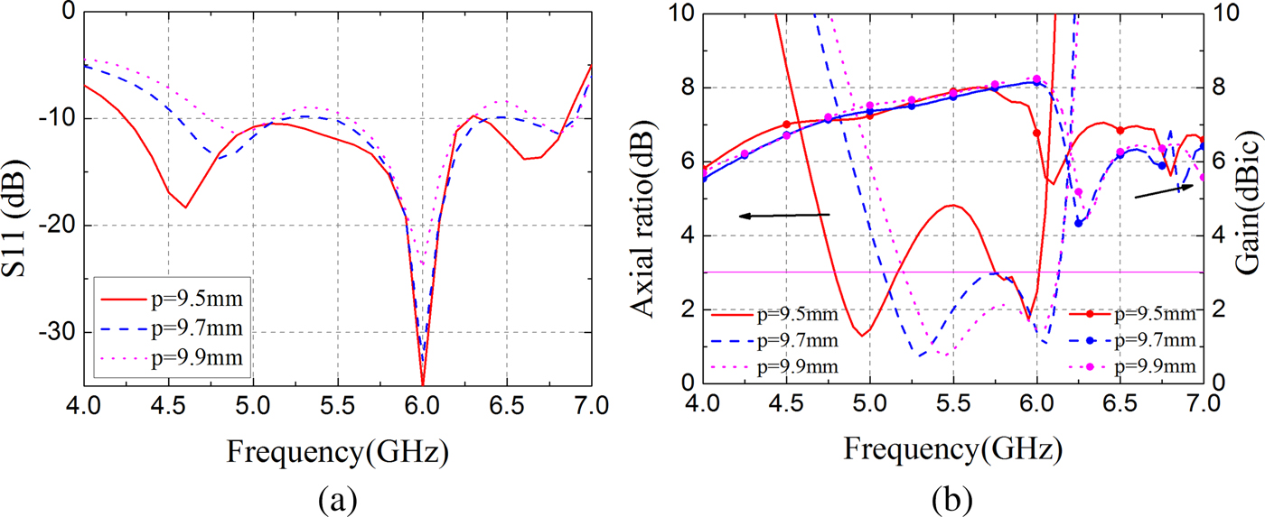
Fig. 11. (a) S 11, (b) AR and gain at different p.
As displayed in Figs 12(a) and 12(b), the length a of the metasurface has a significant influence on the impedance matching and AR BW. From Fig. 12(a), the impedance matching BW is expanded with the length a, which increases from 9.0–9.4 mm. It can be seen from Fig. 12(b) that the two resonant modes shift to lower frequencies with the increases of the length a, which is attributed to increases of equivalent resonant length. The curves of gain also shift to lower frequencies with increases of metasurface length.

Fig. 12. (a) S 11, (b) AR and gain at different a.
The effects of the truncated corner size b on the antenna performances are given in Figs 13(a) and 13(b), respectively. Different from the influence of metasurface length a, the variation of truncated corner size b has much more impact on the impedance matching but less influence on the impedance band shift. Figure 13(a) shows that the impedance matches better with the BW, which is nearly unchanged when the size b increases from 2.5–3.5 mm. Figure 13(b) indicates that the AR BW varies with the increases of the truncated corner size b and split into two resonant frequencies gradually. The curves of gain shift to higher frequencies with the increases of the size b.

Fig. 13. (a) S 11, (b) AR and gain at different b.
In a word, the antenna performances can be tuned by the mentioned parameters. The parameters optimization mainly includes two steps: (1) design of feeding structure and (2) optimization of metasurface. Then the good impedance matching and AR BW are realized.
Fabrication and measurements
In order to verify the simulations and analysis, an oversize of 38.8 mm × 38.8 mm × 3.5 mm antenna was fabricated and measured. Top and bottom views of the sample are shown in Figs 14(a) and 14(b), respectively. The antenna is fed with 50 Ω SMA connector and the reflection coefficient S11 is measured by a vector network analyzer (Agilent PNA Series Network Analyzer E8363B). The measurement can be divided into two steps. First step is the calibration of the vector network analyzer by using a calibration kit (N4692A) before the measurement. Second step is the measurement of S 11. The reflection coefficient of the antenna was obtained.

Fig. 14. (a) Top view and (b) bottom view of the antenna. (c) Schematic view of the antenna measurement setup and (d) testing in an anechoic chamber.
In practical application, we pay more attention on its AR BW, radiation patterns, and gain of CP antenna. Thus, the proposed antenna was tested by Agilent PNA Series Network Analyzer MS4644A and in the anechoic chamber (an overall size of length × width × height is 5 m × 4 m × 3 m). The schematic view of the measurement setup and practical testing are given in Figs 14(c) and 14(d), respectively. As shown in Fig. 14(c), the distance between the standard LP horn antenna and the sample is over 4 m to obtain far-field situation. Far-field can be satisfied according to the distance requirement of over 2D 2/λ, where D is the largest antenna diameter [Reference Kraus and Marhefka24] (physical dimensions of 38.8 mm × 38.8 mm in the case) and λ is the wavelength (42.86 mm at maximum working frequency 7.0 GHz).
Figure 14(d) displays measurement photograph of the radiation patterns and radiation gain. Considering operating BW of the proposed antenna, the standard gain antenna BJ-48 was chosen as a reference antenna, which could cover the BW of 3.94–5.99 GHz. The gain measurement includes three steps. First, the standard gain antenna was placed on the platform as a sample and its gain was measured. Second, the measured gain values were compared with standard gain curve provided by the manufacturer, such that the relative values between the actual gain values and the measured ones in the anechoic chamber of the antenna can be obtained. Third, gain of the proposed antenna was measured. Then the measured results added the relative gain values of the measurement, which are the actual radiation gain of the proposed antenna. It is noted that the results should be compared with the standard gain antenna at the same situation. Thus, we carried on the measurement of the proposed antenna after the measurement of the reference antenna immediately.
To obtain AR of the proposed antenna, a LP horn antenna was employed to measure electric fields along the orientations of the radiation far-field in boresight direction, which are named as E-ϕ ( $\vec E_\phi $) and E-θ (
 $\vec E_\theta $), respectively. The amplitudes and phases of the two components (
 $\vec E_\phi $ and
  $\vec E_\theta $) were measured, then right-handed electric field
  $\vec E_R $, the left-handed electric field
  $\vec E_L $ are calculated according to the expressions
  $\vec E_R = (\vec E_\theta + j\vec E_\phi )/\sqrt 2$,
  $ \vec E_L = (\vec E_\theta - j\vec E_\phi )/\sqrt 2 $. Hence, the AR can be obtained according to the equation:
 $${AR = \left \vert {\left( {\left \vert {\vec E_R} \right \vert + \left \vert {\vec E_L} \right \vert} \right)/\left( {\left \vert {\vec E_R} \right \vert - \left \vert {\vec E_L} \right \vert} \right)} \right \vert}. $$
As can be seen from Fig. 15(a), measured impedance matching BW (S 11 < −10 dB) is 4.40–6.60 GHz (fractional BW of 40%), whereas the simulated one is 4.55–6.95 GHz (41.7% BW). Measured values of AR and gain are depicted in Fig. 15(b). It is shown that about 21% 3 dB AR BW can be achieved in the frequency range of 5.05–6.25 GHz, whereas the simulated one is 5.05–6.15 GHz (fractional BW is about 19.6%). The radiation gain was obtained compared with the standard gain antenna (3.94–5.99 GHz), so that values from 5.00 to 6.00 GHz are given to verify simulations. It is obvious that the curve of measurements has similar tendency with the simulated one and the average gain is about 7.5 dBic. Small frequency shift and deviations compared with simulated ones are acceptable considering fabrication errors and measurement errors. Radiation patterns of xoz-plane and yoz-plane at first resonance mode are given as an example to study radiation performance of the antenna, as shown in Fig. 16. The measured and simulated radiation patterns show good agreement in a broadside radiation. The deviations at back side are mainly caused by measurement errors, such as the influence of testing coaxial cable. Radiation patterns at other frequencies have similar features within the CP operating band.

Fig. 15. (a) Simulated and measured results of S 11. (b) AR and gain.

Fig. 16. Radiation patterns of (a) xoz-plane and (b) yoz-plane at 5.30 GHz.
Measured results of recently reported metasurface-based CP antenna and our work are concluded in Table 1. The comparisons show that the proposed low-profile antenna owns properties of wide impedance matching BW, wide operating AR BW, and high gain. Besides, the coplanar waveguide feeding structure generates compact size and miniaturization.
Table 1. Measured results comparisons of recently reported wideband low-profile CP antenna

Conclusion
In this work, we proposed a wideband CP aperture-coupled antenna based on the metasurface due to the polarization conversion of the patches. The integrated metasurface patches and coplanar waveguide feed structure ensures its compactness and low profile. The theoretical analysis and parametric studies serve as a guideline for wideband design. Simulated results demonstrate about 41.7% impedance matching BW (S 11 < −10 dB) of 4.55–6.95 GHz and 19.6% AR BW of 5.05–6.15 GHz. Besides, an antenna sample was fabricated and measured. The measured results and the simulated ones are in good agreement. The CP antenna is low profile, wideband, and high gain, which shows a potential application for C-band satellite and wireless communication system.
Acknowledgement
The authors thank the reviewers and the editors for their valuable comments and warm work earnestly.
 Qi Zheng was born in Anhui Province, China, in 1993. He received the B.Sc. in Mathematics and Applied Mathematics from the School of Science, Northwestern Polytechnical University (NPU), 2014. Then, he received the M.Sc. in Electromagnetic Field and Microwave Technology from the School of Electronic and Information, NPU, 2016. Now, he is pursuing the Ph.D. degree in Electronic Science and Technology from the School of Electronic and Information, NPU. His research interests include design of reflect array, electromagnetic metamaterials, and RCS reduction. E-mail: zhq930908@mail.nwpu.edu.cn
 Chenjiang Guo was born in Shaanxi Province, China, in 1963. CIE Senior Member, Antenna Society Committee Member. He received the M.Sc., B.Sc, and Ph.D. from the School of Electronics and Information, Northwestern Polytechnical University in Xi'an city, China, in 1984, 1987, and 2007, respectively. He is a professor in the School of Electronics and Information NWPU. He has published more than 140 research papers. His research interests include EMI/EMC, the antenna theory and design, and the microwave circuit design. E-mail: cjguo@nwpu.edu.cn
 Jun Ding was born in Shaanxi Province, China, in 1964. She received the M.Sc., B.Sc., and Ph.D. from the School of Electronics and Information, Northwestern Polytechnical University in Xi'an city, China, in 1986, 1989, and 2005, respectively. She is a professor in the School of Electronics and Information NWPU. She has published more than 100 research papers. Her research interests include electromagnetic metamaterials, the antenna theory and design, and the microwave circuit design. E-mail: dingjun@nwpu.edu.cn


