I. INTRODUCTION
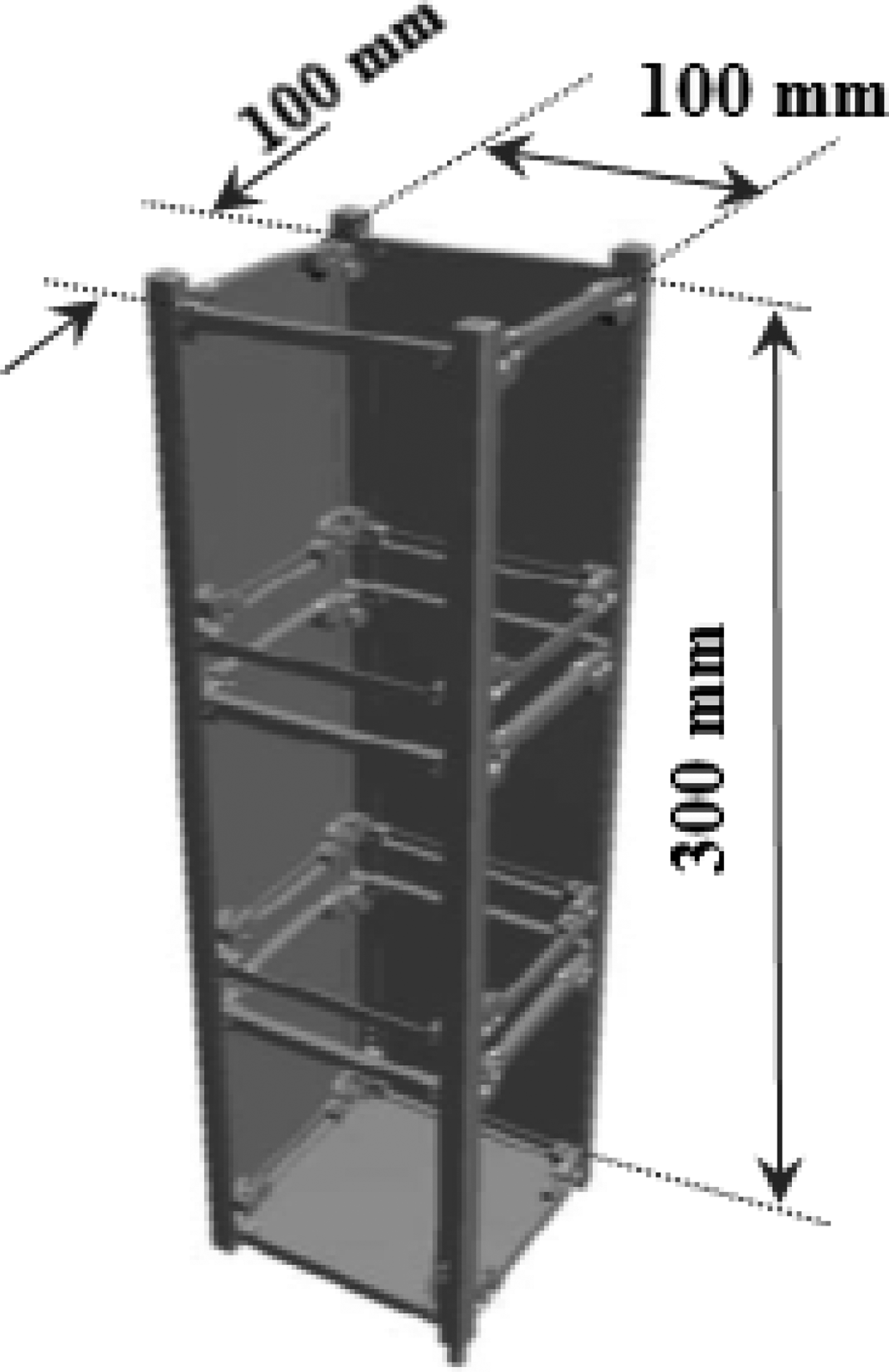
The requests in high data rate of the future nanosatellite missions are incompatible with a telemetry application in very high frequency (VHF) or S bands contrary to the X-band. Moreover, such an application requires wide angle coverage of the earth for a long time visibility, implying a theoretical isoflux radiation pattern. Circular polarization (CP) must be also used for such communications. Over the last few years, many antennas have been identified as good candidates to meet demands for either CP, isoflux pattern or both criteria. The first one is the quadrifilar helix [Reference Kilgus1] which often requires considerable height. This drawback has been partially removed by Duchesne et al. by superposing two radiating elements [Reference Duchesne, LeGoff, Durand, Baracco and Foged2]. Other teams have studied antenna arrays with a circular, hexagonal or aperiodic spatial distribution [Reference Reyna, Panduro and del Rio Bocio3–Reference Ibarra, Reyna, Panduro and del Rio-Bocio5]. Some of them allow a good CP or an isoflux pattern. None of them can perfectly fulfill both conditions unless they have large dimensions. Another solution based on “metasurfaces” has been studied by Albani's and Minatti's teams [Reference Albani, Mazzinghi and Freni6, Reference Minatti, Maci, De Vita, Freni and Sabbadini7] but it also requires large dimensions. Finally one of the most used antennas is the choke horn. This one is employed since a long time for satellite communications. In this study, it will be again designed to ensure good performances and correct antenna dimensions. This kind of antenna was first used to feed a parabolic antenna with a focal length to diameter ratio (F/D) lower than 0.3 [Reference Milligan8]. Geyer [Reference Geyer9] and LaGrone [Reference LaGrone and Roberts10] introduced a corrugated flange on the circular waveguide aperture in 1966. Wohlleben et al. [Reference Wohlleben, Mattes and Lochner11] and Shafai [Reference Shafai12] have respectively improved in 1972 and 1977 this method in order to increase the radiating aperture angle. Brachat gives an approximate synthesis design process for this kind of antenna in 1994 [Reference Brachat13]. Finally other teams have improved the design using different calculation methods as those of Garcia-Muller, Ravanelli Kyung-Jin Jeon teams [Reference Garcia-Muller14–Reference Jeon, Lee, Son, Lee, Lee and Lee16]. All these antennas generally imply a large size which becomes unsuitable for a nanosatellite platform. Indeed, two platforms are considered for this study: a platform type named cubesat 3U as presented in Fig. 1 (100 × 100 × 300 mm) and a second one named cubesat 6U (200 × 100 × 300 mm).

Fig. 1. View of the platform “cubesat 3U”.
The proposed design consists in a tradeoff between the isoflux radiation pattern quality and antenna compactness, i.e. a tradeoff on two parameters.
• X mg which is the difference between the maximum and the boresight gain;
• θ mg which is the angle where the gain is maximum.
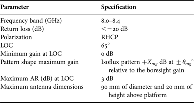
Table 1 presents the antenna requirements. The ideal case is X mg = +3 dB and θ mg = ±65°.
Table 1. Antenna requirements.

This paper is organized as follows. First, Section II presents the design of a compact choke horn with an axial ratio (AR) lower than 3 dB and a gain higher than 0 dB over a 400 MHz bandwidth (8.0–8.4 GHz) with or without the platform presence. The comparison of measured and theoretical results is presented in Section III. Finally, a conclusion is given in the last section.
II. ANTENNA DESCRIPTION
The design method involves a three-step simulation process which has been carried out using CST Microwave Studio. The first step is the simulation and the optimization of the compact choke horn fed by a perfect waveguide port, i.e. two modes spatially and temporally shifted by 90° at the central frequency (8.2 GHz) are considered. It allows determining geometric parameters with respect to the mechanical constraints and the electromagnetic specifications previously mentioned. The second step is the feed simulation which gives the best results in terms of CP and matching. The last step is the simulation of the whole antenna with or without platform.
A) The compact choke horn
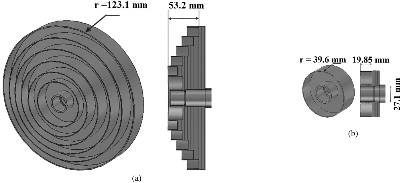
The initial design based on the work from Brachat [Reference Brachat13] is presented in Fig. 2(a). Its radius and height are too important for the application and a reduction is required in order to satisfy the specifications. The new optimized design appears in Fig. 2(b) where both radius and height have been reduced from 123 to 40 mm and from 53 to 20 mm, respectively. Only one corrugation has been kept. Figure 3 shows the simulated results of the new design. The right- and left-hand CP (RHCP and LHCP) radiation patterns (realized gain (RG) drawn in the φ = 0° cut plane) have an isoflux shape (Fig. 3(a)) over the whole frequency band. However, the angle where the maximum gain is not obtained at the expected limit of coverage (LOC) but for an elevation angle (θ gm) equals to 35°. The maximum gain level is greater than 3 dB relative to the boresight gain. The RG (Fig. 3(b)) is almost greater than 0 and the AR (Figs 3(c) and 3(d)) is almost lower than 3 dB at the LOC whatever the azimuth angle (φ). Finally, the simulated electromagnetic requirements are obtained except the elevation angle (θ gm) and the gain level (X mg) when the mechanical constraints are taken into account.

Fig. 2. Comparison of the design from Brachat (left) and the proposed one (right).

Fig. 3. Simulated RHCP and LHCP radiation patterns (φ = 0° plane) (a), Simulated RG at θ = 65° versus azimuth angle (b), simulated AR radiation patterns (φ = 0° plane) (c), simulated AR at θ = 65° versus azimuth angle (d).
B) The antenna feed
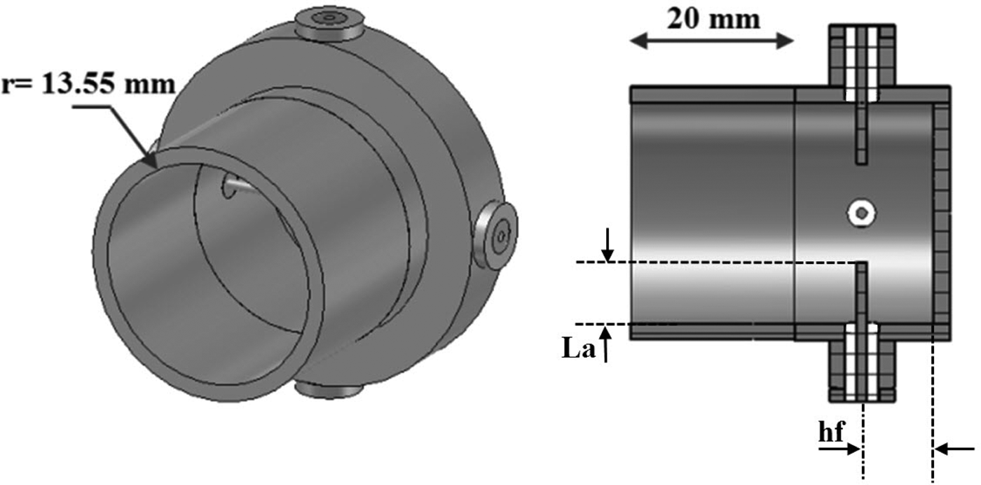
The second step is the feed simulation. To ensure the best AR, a device with four coaxial probes spatially and temporally-shifted by 90° and placed in the same z-plane has been chosen (Fig. 4). The waveguide output has been extended by 20 mm for the establishment of the propagation modes. The AR radiation patterns and the return loss are then obtained.

Fig. 4. Simulation of the feed: (four coaxial probes).
The parameters (L a) and (h f) have been optimized to minimize the return loss on each port. It is lower than −20 dB over the operating frequency band. Figures 5(a) and 5(b) show, respectively, the simulated AR radiation patterns (φ = 0° plane) and those obtained at θ = 65° versus azimuth angle. They are close to the expected AR level at the LOC whatever the azimuth angle (φ). Now, the association of the horn and the feed has to be investigated.

Fig. 5. Simulated AR radiation patterns (φ = 0° plane) (a), simulated AR at θ = 65° versus azimuth angle (b).
C) The whole antenna
The last step is the whole antenna simulation without and with 3U or 6U platform.
1) ANTENNA WITHOUT PLATFORM
Figure 6 presents the geometry of the whole antenna (choke horn and feed) without the platform. The dimension h (15.9 mm) has been optimized to ensure good performances. The whole antenna results are similar to the ones aforementioned. The combination of the two systems does not degrade the electromagnetic characteristics. Notice that these simulation results do not include the four-way divider insertion losses.

Fig. 6. Simulation of the whole antenna.
2) ANTENNA WITH PLATFORM
Figures 7(a) and 7(b) present, respectively, the geometry of the whole antenna with the 3U or 6U platforms simulated as a perfect electric conductor cube. The horn aperture is placed at 19.85 mm above the nanosatellite platform (initial height). The 3U results are similar to those without platform. However, those of the 6U platform are damaged because the structure is nonsymmetrical (Figs 8(a)–8(d)). The simulated RHCP and LHCP radiation patterns (φ = 0° plane) are not symmetrical. At θ = 60°, the AR increases up to about 6 dB.

Fig. 7. Simulation of the whole antenna with the 3U (a) or 6U (b) platform.

Fig. 8. 6U platform: simulated RHCP and LHCP radiation patterns (φ = 0° plane) (a), simulated RG at θ = 65° versus azimuth angle (b), simulated AR radiation patterns (φ = 0° plane) (c), simulated AR at θ = 65° versus azimuth angle (d).
A solution to reduce the 6U platform effect is to put the antenna inside the platform. One case has been tested. The horn aperture is placed at the top of the nanosatellite platform without changing the antenna design. The evolution of the AR versus θ and φ is presented on Figs 9(a) and 9(b) for three frequency values. An improvement appears in comparison with Fig. 8(c) particularly around θ = 60° angle.

Fig. 9. 6U platform and 0 mm: simulated AR radiation patterns (plane φ = 0°) (a), simulated AR at θ = 65° versus azimuth angle (b).
III. MEASUREMENT AND SIMULATION RESULTS
The antenna has been realized and measured. For the measurement, the antenna is positioned on a device which simulates the top of 3U or 6U platform (Figs 10(a)–10(c)). A 4-way divider with phase shifter (0°, 90°, 180°, and 270°), hand-formable coaxial cables and right angle adapters are used for the antenna feed. The total insertion losses are around 0.9 dB Figs 11(a) and 11(b) present the 4-way divider with phase shifter performances. The amplitude and phase unbalance are respectively lower than ±0.2 dB and ±7°. The scattering parameters of a divider has been expressed in touchstone format and introduced in the new simulation.

Fig. 10. Drawing (bottom view (a), 3U perspective view (b), and 6U perspective view (c)) and the photography (d) of the manufactured antenna positioned on our antenna test range support.

Fig. 11. Four-way divider with phase shifter performances: amplitude unbalance (a) and phase unbalance (b).
A) 3U platform
The horn is positioned at the initial height. Figure 12(a) shows a comparison between the simulated and measured return loss. Both are similar and in agreement with the desired requirements. It is the same for the directivity and the RG (Fig. 12(b)). The total efficiency with this feed is about 80% which is due to the insertion loss of the antenna feed. There is a good agreement between the simulated and measured RHCP and LHCP radiation patterns (Figs 12(c)–12(d)). It is not possible to have the RG greater than 0 as envisaged for the same reasons (Fig. 12(e)). Also the measured AR radiation patterns (plane φ = 0°) and AR at θ = 65° versus azimuth angle (φ) are close to the simulated ones (Figs 12(f)–12(g)). They meet the desired antenna specifications. All the results are similar if the horn is inside the 3U platform.

Fig. 12. 3U Platform: return loss (a), directivity and realized gain (b), simulated RHCP and LHCP radiation patterns (φ = 0° plane) (c), measured RHCP and LHCP radiation patterns (φ = 0° plane) (d), RG at θ = 65° versus azimuth angle (e), AR radiation patterns (plane φ = 0°) (f), AR at θ = 65° versus azimuth angle (g).
B) 6U platform
In this case, the horn aperture is placed at the top of the 6U platform. Figures 13(a)–13(g) present a comparison of measured and theoretical antenna performances. All the remarks aforementioned are still valid to conclude on this configuration. Moreover, RHCP and LHCP radiation patterns are disturbed as expected but they meet the desired antenna specifications.

Fig. 13. 6U Platform: return loss (a), directivity and realized gain (b), simulated RHCP and LHCP radiation patterns (φ = 0° plane) (c), measured RHCP and LHCP radiation patterns (φ = 0° plane) (d), RG at θ = 65° versus azimuth angle (e), AR radiation patterns (φ = 0° plane) (f), AR at θ = 65° versus azimuth angle (g).
IV. CONCLUSION
This paper presents an X-band compact choke horn antenna with CP and isoflux pattern installed onto the 3U or 6U nanosatellite platform. A tradeoff between isoflux pattern quality and antenna compactness has been done. Excellent numerical results with an AR lower than 3 dB and a RG close to 0 dB whatever azimuth angle (φ) on the 8.0–8.4 GHz frequency band have been obtained except for the angle where the gain is maximum (θ = 35° instead 65°). A prototype has then been realized to demonstrate the feasibility of such a structure. The measurement results are in excellent agreement with the theoretical ones.
ACKNOWLEDGEMENTS
The authors would like to thank CNES (Centre National d'Etudes Spatiales) – FRANCE who has financially supported this study.


