


I. INTRODUCTION
Long-term evolution (LTE) is the fourth stage of the evolution of mobile networks, and therefore is considered as the fourth generation (4G). The LTE operation can provide better mobile broad band and multimedia services than the existing GSM and UMTS mobile networks and is expected to become attractive for the mobile users [Reference Lizzi and Massa1]. There are various designs used in internal mobile terminal applications, such as monopoles [Reference Du, Gong and Fu2], loop antennas [Reference Chi and Wong3], slot antennas [Reference Lin and Wong4], inverted-F-shaped wire-form antennas (IFAs) [Reference Lin, Tang and Chang5], planar inverted-F antennas (PIFAs) [Reference Kim, Lee, Cho and Lee6, Reference Lee, Harackiewicz and Wi7], and balanced antennas [Reference Zhou, Abd-Alhameed, See, Alhaddad and Excell8]. In addition, many antennas are capable of generating two wide operating bandwidths to cover the most common standards for mobile phone applications [Reference Yang, Huang and Jou9–Reference Chen and Lee20].
A multiband loop antenna is presented in [Reference Lin and Wong11]. Its loop pattern has two symmetric meandered sections and a central widened section, while the central widened section has a size of 9 × 15 mm2, and the antenna portion occupies a volume of 12 × 45 × 7 mm3. The antenna can provide two wide operating bands to cover the desired frequency ranges of 888–978 and 1670–2170 MHz, which includes the GSM850/GSM900/DCS1800/PCS1900/UMTS 2100 bands (824–896/880–960/1710–1880/1850–1990/1920–2170 MHz). In [Reference Zheng, Wang and Hao12], an internal hexa-band-folded antenna with four resonances for mobile devices is investigated. This antenna, formed by a single continuous loop element with two connections to the PCB through a feeding point and a grounding point, takes a small volume of 50 × 13 × 5 mm3. The antenna can generate two wide operating bands to cover the frequency ranges of 698–960 and 1710–2170 MHz.
The authors in [Reference Jeon, Oh, Kim and Kim15] propose a double planar inverted-E (PIE) antenna. The design antenna is formed by an antenna element, a feedline, a shorting line, two shunt capacitors, and a ground plane and occupies a size of 60 × 10 × 3 mm3. On the other hand, two wide operating bandwidths covering 698–990 and 1700–2170 MHz are achieved. As reported in [Reference Li, Zhang, Zheng, Feng and Iskander16], a compact folded loop-inverted F reconfigurable antenna is demonstrated. By using one PIN diode with a simple bias circuit, both the loop and IFA modes are controlled, and the antenna occupies a small volume of 60 × 5 × 5 mm3 and can support only the GSM 850/GSM900/GPS/DCS/PCS/UMTS/WLAN. Article [Reference Ishimiya, Chiu and Takada17] discusses a multiband loop antenna with a small volume of 68 × 5 × 3.3 mm3 for GSM850/GSM900/DCS/PCS/UMTS.
In this paper, we propose a novel compact printed loop antenna for smartphone applications. The proposed antenna consists of meander loop antenna, which is connected to the ground plane and a capacitively coupled feeding line. The antenna shows a planar structure, with the overall dimension of 120 × 60 mm2 and the antenna portion occupying a small size of 20 × 60 mm2, which makes it suitable for practical smartphone applications. In addition, the prototype antenna can provide two wide lower and upper bands to respectively cover the frequency range of 712–1078 and 1757–2930 MHz, including the LTE700/GSM850/GSM900 and the DCS1800/PCS1900/UMTS2100/IMT2000/LTE2300/LTE2500/WLAN2400/ISM2450 operation. The obtained results show good performance in terms of antenna gain and radiation patterns. The configuration of the antenna, parametric studies, and results of the constructed prototype are presented and discussed in the following sections. The specific absorption rate (SAR) results of the proposed antenna placed at the bottom of the mobile phone are also analyzed and calculated according to the FCC standard (1.6 W/kg over 1 g tissue) and ICNIRP standard (2 W/kg over 10 g tissue). Two human head models have been implemented: an homogenous spherical head model and a Specific Anthropomorphic Mannequin (SAM) phantom head provided by CST MWS. We used Ansoft HFSS software and CST MWS to run all simulations and to calculate the SAR values.
II. ANTENNA CONFIGURATION AND DESIGN METHODOLOGY
A) Antenna design geometry
The configuration of the presented novel compact printed loop antenna for WWAN/WLAN/ISM/LTE smartphone applications is depicted in Fig. 1. The design of the antenna is based on an inexpensive FR4 substrate, which has a relative permittivity of 4.4, a loss tangent of 0.02 and a thickness of 1.6 mm and is used as the system circuit board. On the front side of the substrate, a meander loop with a total length of 372 mm and a width of 1 mm, and a system ground plane with a length of 100 mm and a width of 60 mm are printed in the same face of the FR4 substrate. The back side of the substrate consists of a capacitively coupled feeding line, which is composed of three stubs (stub1, stub2, and stub3) and connected to a 50 Ω microstrip line located at the center of the ground plane with a width of 3 mm. The essential role of the three stubs is to obtain a better impedance matching and to achieve a wide bandwidth in the lower and upper bands. The effects of the lengths and locations of these three stubs on the antenna performance are analyzed in the next section. The overall dimensions of the proposed antenna (120 × 60 mm2) and the antenna portion (meander loop) (20 × 60 mm2) are suitable for the smartphone application. The detailed dimensions of the proposed prototype antenna are optimized by using a full-wave electromagnetic simulator, Computer Simulation Technology Microwave Studio CST MWS, which is based on Finite Integration Technique (FIT).The different optimized parameters of the proposed antenna are given in Table 1.
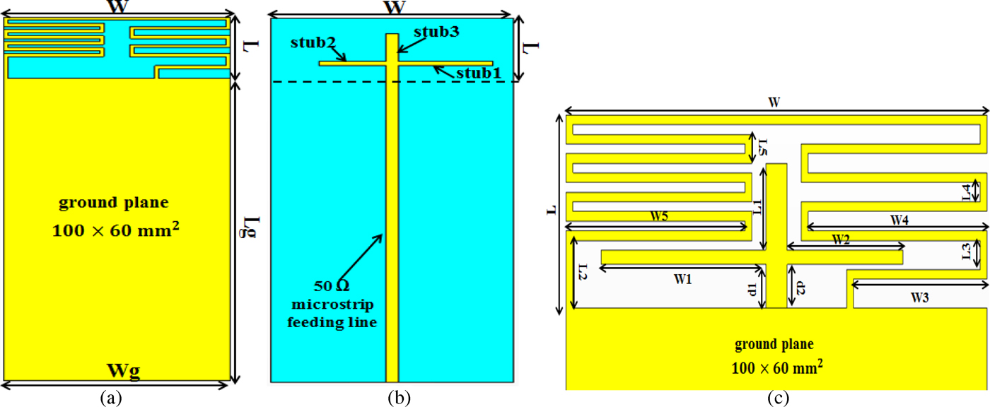
Fig. 1. Geometry of the proposed internal compact printed loop antenna for WWAN/WLAN/ISM/LTE smartphone applications. (a) Front view. (b) Back view. (c) Dimensions of the antenna in its planar structure.
Table 1. Optimized values for the geometric parameters of the proposed antenna (unit in mm).
B) Comparing the effect between the antenna with direct feed and coupling feed
The simulated results are performed by using the CST Microwave Studio. The proposed antenna was firstly designed as a meandered loop antenna and subsequently step-by-step developed into a capacitively coupled feed loop antenna. The dimensions of the meander loop antenna shown in Fig. 2(b) are the same as the ones given in Table 1. Figure 2(a) plots the simulated reflection coefficient versus the frequency for the proposed antenna by using the capacitive coupled feed technique compared with the loop antenna excited by using a 50 Ω mini coaxial cable at the feeding point A as illustrated in Fig. 2(b). As shown in Fig. 2(a), by using the direct feeding technique many peaks appear with a narrow bandwidth, whereas, when changing the feeding method, we observe that the proposed antenna can provide three wide frequency bands, which covers multi-band for the GSM, DCS, PCS, UMTS, IMT2000, WLAN, ISM2450, and LTE.
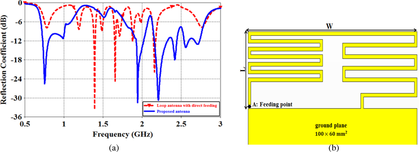
Fig. 2. (a) Simulated reflection coefficient of the proposed antenna and loop antenna with direct feeding technique. (b) Dimensions of the loop antenna with direct feeding.
In order to evaluate the effects of the capacitively coupled feed technique on generating the antenna's lower and upper bands, Figs 3(a) and 3(b) illustrate a comparison between the simulated input impedance and the frequency of the proposed antenna and the loop antenna with direct feeding. From Fig. 3(b), we observe that the imaginary (Im) part of the desired lower band impedance is very low, whereas, its real part (Re) is much higher, in comparison with the proposed antenna, which has a good impedance matching especially at around 755 MHz, as shown in Fig. 3(a). For the desired upper band, both the real (Re) and Im parts of the input impedance for the proposed antenna are smaller than that of the antenna with direct feeding. Moreover, they are both closer to 50 and 0 Ω, respectively.
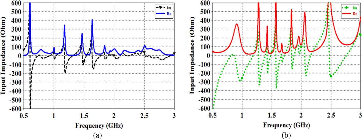
Fig. 3. Simulated input impedance for (a) the proposed antenna and (b) the loop antenna with direct feeding.
This comparison shows the importance of using the coupling feed technique compared with the direct feed method in order to achieve a good impedance matching in the lower and upper bands and to enhance the bandwidth.
C) Parametric study of the proposed antenna
Several important design parameters of the proposed antenna are analyzed in this section. In these studies, only one parameter is varied while, the other dimensions are the same as given in Table 1. The parametric study has been carried out by using the commercial program CST Microwave Studio.
1) EFFECT OF W 1, W 2, D 1, AND D 2 ON THE PERFORMANCE OF THE PROPOSED ANTENNA
In the first section, we studied the effects of the lengths of the two stubs (stub1 and stub2) on the reflection coefficient of the presented antenna to see how it affects the impedance matching and bandwidth of the proposed antenna. The effects of varying the length W 1 of the stub1 are investigated and shown in Fig. 4(a). The other dimensions are the same as the ones given in Table 1. Results for value W 1 are presented and vary from 7.5 to 23.5 mm. Large effects of the length W 1 on the antenna's lower bands are observed. When increasing the length W 1, the impedance matching of the upper band is improved. Figure 4(b) demonstrates the simulated reflection coefficient as a function of the length W 2. Results for the length W 2 vary from 5.5 to 16.5 mm and are depicted in Fig. 4(b). There are no variations in the impedance matching of the lower band, and large effects on the impedance matching of the antenna's upper band are observed. The simulated reflection coefficient versus the frequency curves with two different distances d 1 and d 2 vary from 4.5 to 6.5 mm and are plotted in Figs 5(a) and 5(b), respectively. Notice that d1 and d2 are the distances from the ground plane edge to stub1 and stub2, respectively, as illustrated in Fig. 1. Large effects on the lower and upper bands are seen by varying d 1 and d 2 from 4.5 to 6.5 mm.
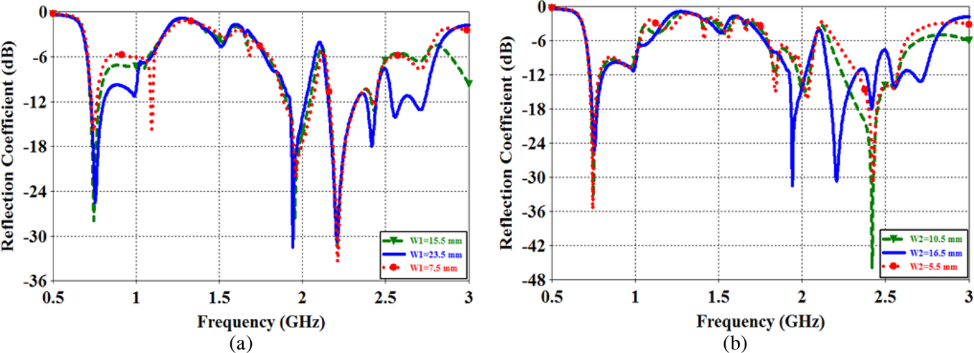
Fig. 4. Simulated reflection coefficient as a function of (a) the length W 1 and (b) the length W 2. Other dimensions are the same as given in Table 1.
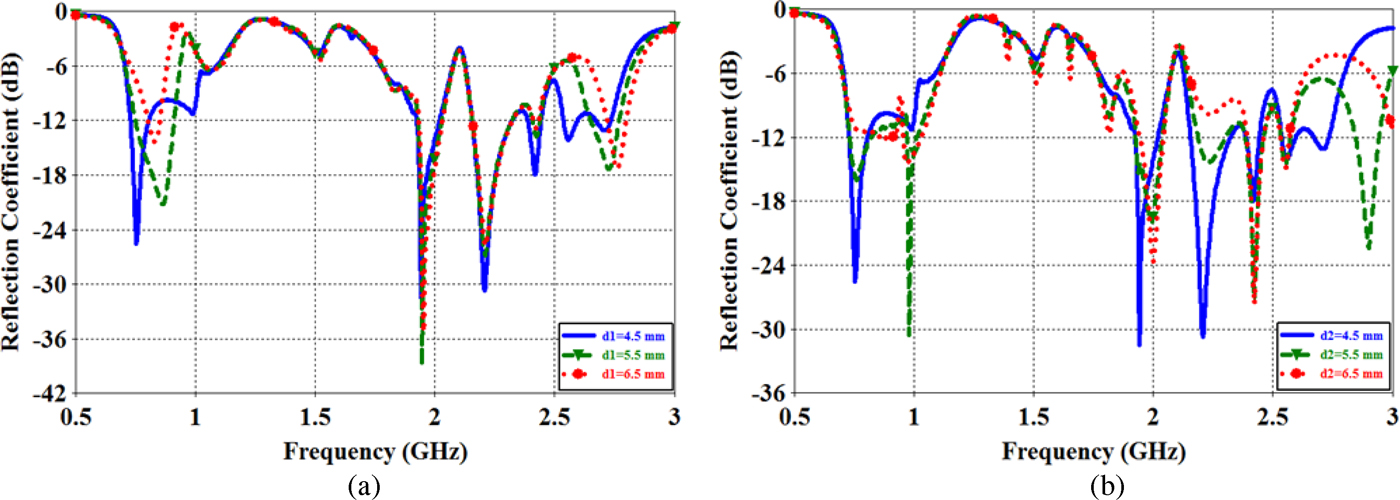
Fig. 5. Simulated reflection coefficient as a function of (a) the distance d 1 and (b) the distance d 2. Other dimensions are the same as given in Table 1.
2) EFFECT OF D 1 = D 2 AND L 1 ON THE PERFORMANCE OF THE PROPOSED ANTENNA
The effects of the distance d 1 = d 2 are also studied in Fig. 6(a). The results for d 1 = d 2 vary from 4.5 to 6.5 mm and clearly indicate that the antenna's lower and upper bands can be effectively controlled by adjusting the respective distance d 1 = d 2. Figure 6(b) plots the curves of the simulated reflection coefficient for the proposed antenna as a function of the length L 1 of stub3. We observe from Fig. 6(b) that changing the length L 1 from 3 to 9 mm affects the impedance matching of the lower band and the upper bandwidth coverage.
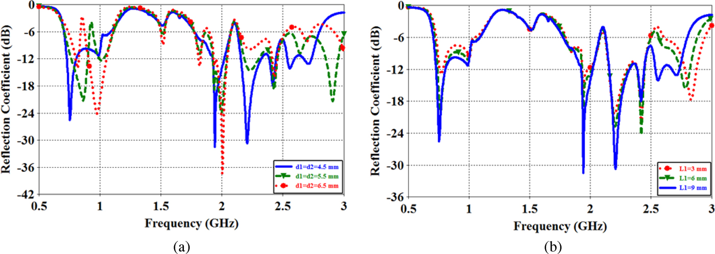
Fig. 6. Simulated reflection coefficient as a function of (a) the distance d 1 = d 2 and (b) the length L 1. Other dimensions are the same as given in Table 1.
3) EFFECT OF THE LENGTH L G OF THE SYSTEM GROUND PLANE
The effects of the parameter L g of the system ground plane on the performances of the proposed antenna are depicted in Fig. 7. The simulated reflection coefficient for the length L g varies from 70 to 100 mm. When the length L g decreases, all the resonant modes and impedance matching of the lower and upper bands are affected. In this design antenna, the preferred length L g is determined to be 100 mm from the obtained results.
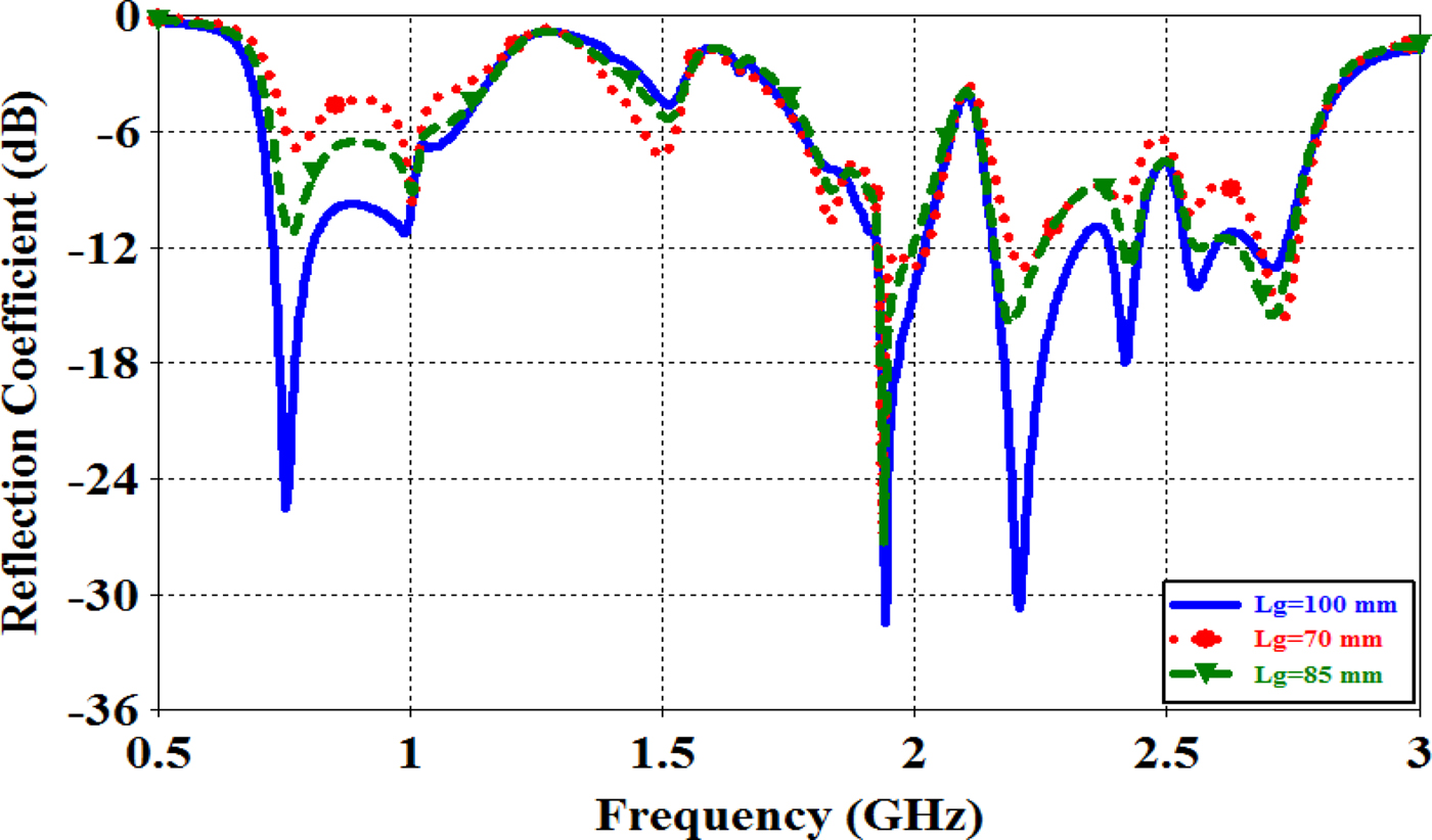
Fig. 7. Simulated reflection coefficient as a function of the length L g of the main ground plane. Other dimensions are the same as given in Table 1.
III. PROTOTYPE FABRICATION AND MEASUREMENT RESULTS
To evaluate the performance of the compact printed loop antenna for WWAN/WLAN/ISM/LTE smartphone applications, a prototype was fabricated and measured. The antenna was fabricated with the optimized geometric parameters listed in Table 1. The prototype antenna was fabricated using an LPKF ProtoMat S63 machine at the STRS Microwave Laboratory, National Institute of Posts and Telecommunications-INPT. Figure 8 shows the photographs of the fabricated printed loop antenna. The proposed prototype antenna is connected to a 50 Ω SMA connector for signal transmission.

Fig. 8. Photographs of the fabricated prototype of the proposed antenna in different views. (a) Front view of the fabricated antenna. (b) Back view of the fabricated antenna. (c) Top side.
Based on the design dimensions illustrated in Table 1, the proposed antenna was fabricated and tested. The measured and simulated reflection coefficients versus the frequency for the constructed prototype are depicted in Fig. 9. The simulated results of the CST Microwave studio are compared with the Ansoft High Frequency Structure Simulator HFSS, which is based on finite-element method (FEM), whereas the measured results are tested by Anritsu Vector Network Analyzer Master MS2028C.

Fig. 9. Measured and simulated reflection coefficient by using CST MWS and Ansoft HFSS for the proposed antenna.
A good agreement between the measurement data and simulation is observed. The small difference between the simulated and measured results can be due to manufacturing tolerance and imperfect soldering effect of the SMA connector .In all the results, the bandwidth is defined by a 3 : 1 VSWR or a −6 dB reflection coefficient that is generally acceptable for practical mobile phone antennas. From the measured results, we observe that the antenna is capable of generating two wide operating bands. The lower band shows a wide bandwidth of 366 MHz (712–1078 MHz), whereas the upper band has an even wider bandwidth of 1173 MHz (1757–2930 MHz). The wide lower and upper bands cover the LTE700/GSM850/GSM900 and DCS1800/PCS1900/UMTS2100/IMT2000/LTE2300/LTE2500/WLAN2400/ISM2450 operation, respectively.
A) Current distribution
In order to evaluate the characteristics of the proposed antenna in more details, the simulated surface current distributions on the printed metal portion of the proposed antenna at typical frequencies (755, 900, 1800, 1942, 2200, and 2420 MHz) are demonstrated in Fig. 10. The red area indicates a strong surface current distribution whereas the green area indicates a weak surface current. Strong excited surface current distributions at 755 and 900 MHz are seen in the meander loop and especially in stub1, compared to those at higher frequencies. Also, at 2200 MHz the meander loop is less excited, but large surface currents are observed in the stub2. On the other hand, relatively strong surface current distributions are seen in the meander loop and the two stubs at 2420 MHz compared to 2200 MHz.

Fig. 10. Simulated surface current distributions at 755, 900, 1800, 1942, 2200, and 2420 MHz.
B) Radiation characteristics
To further demonstrate the proposed antenna performances, radiation gain patterns of the prototype antenna are investigated. Figure 11 plots the three-dimensional (3D) gain radiation patterns at typical frequencies (755, 900, 1800, 1942, 2200, and 2420 MHz) and shows a dipole-like radiation pattern with omnidirectional radiation at 755 and 900 MHz, while more variations in the radiation patterns are observed at 1800, 1942, 2200, 2300, and 2420 MHz.

Fig. 11. Gain radiation patterns in 3D at 755, 900, 1800, 1942, 2200, 2300, and 2420 MHz.
Figure 12 shows the two-dimensional (2D) radiation patterns in three principal planes, namely, the (φ = 0°), (φ = 90°), and (θ = 90°) planes of the proposed printed loop antenna, at the selected operating frequencies, including 755, 900, 1800, 2200, and 2420 MHz. We observe dipole-like radiation patterns in the lower band, and an omnidirectional radiation in the plane (φ = 0°). The radiation patterns in the higher band in planes (φ = 90° and θ = 90°) display, more variations and nulls. These characteristics are similar to those observed for the conventional internal mobile phone antenna.

Fig. 12. Radiation patterns in 2D at (a) 755 MHz, (b) 900 MHz, (c) 1800 MHz, (d) 2200 MHz, and (e) 2420 MHz for the proposed antenna (![]() dB(EPhi),
dB(EPhi), ![]() dB(ETheta)).
dB(ETheta)).
C) Antenna peak gain
Figure 13 demonstrates the peak gains versus the frequency of the prototype antenna in two wide bands. For the operating band of 706–1100 MHz (in Fig. 13(a)), the peak gain varies from about 1.3–2.4 dB, and the antenna exhibits stable and suitable gain over the lower operating band. For the higher operating band of 1775–2800 MHz (in Fig. 13(b)), the peak gain varies from 1.42 to 4.3 dB. From the obtained results, the proposed antenna has reasonable antenna gains over the frequency bands of interest, which is acceptable for practical mobile phone applications.
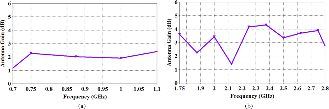
Fig. 13. Peak antenna gain across the operating bands for the proposed antenna, (a) low-frequency band and (b) high-frequency band.
D) Proposed antenna with packaging
The proposed antenna, without a plastic housing is illustrated in Fig. 1. The simulated results were also obtained with the presence of the plastic housing of the antenna system. Moreover, to simulate practical mobile phone casing, a plastic casing with a 1 mm-thick plastic housing, a relative permittivity of 3.0 and a conductivity of 0.02 S/m, is used to enclose the system circuit board with a gap of 2 mm in distance between the plastic casing and the system circuit board, as shown in Fig. 14(a). The height of the plastic housing is 12 mm, an attractive height for thin mobile phones, and the proposed printed loop antenna is at the center of the plastic housing. Figure 14(b) describes the reflection coefficient against frequency about the two cases (with or without the presence of the plastic housing) for the presented antenna. From the obtained results, the proposed antenna covers all the desired operating bands in both cases.
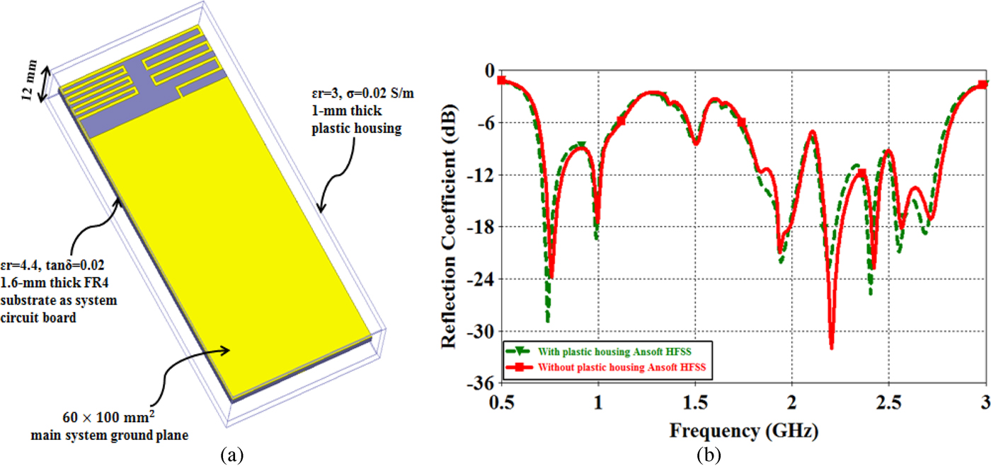
Fig. 14. (a) Proposed antenna with packaging, (b) simulated reflection coefficient against frequency about the two cases (with or without the presence of the plastic housing) for the proposed antenna.
E) Comparison with published work
To evaluate the performance of the fabricated prototype antenna, Table 2 summarizes a comparison of the antenna size, the area it occupies, and its bandwidth, with the existing antennas ([Reference Lee, Harackiewicz and Wi7–Reference Jeon, Oh, Kim and Kim15] and [Reference Wong and Chen18–Reference Chen and Lee20]). The table shows that the proposed antenna has a low profile and a small size except ([Reference Wong and Chen18–Reference Chen and Lee20]). On the other hand, in terms of bandwidth the prototype antenna is capable of generating two wide operating bands of 712–1078 and 1757–2930 MHz, including the LTE700/GSM850/GSM900 and DCS1800/PCS1900/UMTS2100/IMT2000/LTE2300/LTE2500/WLAN2400/ISM2450 operation.
Table 2. Comparison between the proposed antenna performance and other reported antennas.
* Bandwidth does not exist.
IV. SAR ANALYSIS OF THE PROPOSED ANTENNA
The SAR is a measure of power radiated and absorbed by the human body over a specific volume of the head tissue and calculated in terms of Watts/kilogram (W/kg) [Reference Husni, Islam, Faruque and Misran21]. The SAR is defined as:
 $${\rm SAR} = \displaystyle{{\sigma \left \vert E \right \vert ^2} \over {2\rho}}, $$
where σ is the tissue conductivity (S/m), E is the root-mean-square (rms) electric field (V/m), and ρ is the tissue density (kg/m3).
For mobile phone compliance, the SAR value must not exceed the exposure guidelines [22, Reference Jammet23]. For example, the SAR limit specified in IEEE C95.1: 1999 is 1.6 W/kg in a 1 g averaging mass while that specified in ICNIRP guidelines is 2 W/kg in a 10 g averaging mass [Reference Fung, Leung and Chan24].The regulation in SAR has been harmonized to 10 g with a limit of 2 W/kg specified in IEEE C95.1: 2005 with the major difference discussed in detail in [Reference Lin25].
The simulated SAR values of the prototype antenna are investigated using Ansoft HFSS and CST MWS. For this research, we implemented two human head models. The first model is a homogenous spherical head model with a radius of 100 mm, consists of a glass shell with 5 mm thickness and dielectric constant ε r = 4.6, and a sphere with 95 mm radius as the head equivalent materials [Reference Belrhiti, Riouch, Tribak, Terhzaz and Sanchez26, Reference Belrhiti, Riouch, Tribak, Terhzaz and Sanchez27]. Properties of the head tissue-equivalent dielectric and the glass shell are presented in Table 3 [Reference Belrhiti, Riouch, Tribak, Terhzaz and Sanchez26–28]. The second model is a SAM phantom head provided by CST MWS, composed of two layers namely shell and fluid. The gap distances between the antenna and the human head model are 5, 10, and 20 mm. In the study, the mobile phone, with the proposed antenna, is positioned at the bottom of the system circuit board. The input power for testing the SAR is 24 dBm or 0.25 W for 859 and 900 MHz and 21 dBm or 0.125 W for 1800, 1900, 2000, 2300, and 2600 MHz.
Table 3. Properties of the tissue-equivalent dielectric used for the spherical head model.
We also researched the effect of the gap distance between the proposed antenna and the homogenous spherical head model on the SAR distribution. The variation levels of the local SAR and the SAR averaging over a mass of 1 and 10 g, at various gap distances (5, 10, and 20 mm) between the prototype antenna and the homogenous spherical head model at typical operating frequencies of 1800,1900, 2000, and 2600 MHz is illustrated in Fig. 15. The figure shows that the levels of the local and the average SAR increases when the gap distance decreases. Moreover, when penetrating the homogenous head, the SAR levels for 1800, 1900, 2000, and 2600 MHz decrease rapidly.

Fig. 15. Local SAR and average SAR variation in 1 and 10 g head tissues for the homogenous spherical head model, at different frequencies at various gap distances.
The corresponding simulated 3D 1 g SAR (W/kg), at the selected operating frequencies of 859, 900, 1800, and 1900 MHz, and 10 g SAR (W/kg) distributions, at the frequencies of 900, 2000, 2300, and 2600 MHz, inside the SAM phantom head model are presented in Figs 16(a) and 16(b), respectively, and were, obtained by using CST MWS, the gap distance being fixed to 5 mm.

Fig. 16. Simulated 3D (a) 1 g SAR distributions (W/kg), at the frequencies of 859, 900, 1800, and 1900 MHz, and (b) 10 g SAR distributions (W/kg), at the frequencies of 900, 2000, 2300, and 2600 MHz, inside the SAM phantom head model, with 5 mm gap distance using CST MWS.
Table 4 gives a summary of the simulated SAR values inside the homogenous spherical head model and SAM phantom head, at the aforementioned operating frequencies for 1 and 10 g head tissues obtained using CST MWS. As shown in the table, the SAR values for 1 and 10 g head tissues decrease when the gap distance increase from d = 5 to d = 20 mm. When the gap distance is fixed to 5 mm, the SAR values for 1 and 10 g head tissues are all below 1.24 and 1.01 W/kg, respectively, for the homogenous head. The peak 1 and 10 g SARs are all below 1.38 and 1.13 W/kg, respectively, for the SAM phantom head. For d = 10 mm, the peak 1 g SAR values for the SAM phantom, are 1.09, 1.14, 0.521, 0.414, 0.428, 0.562, and 0.551 W/kg, at 859, 900, 1800, 1900, 2000, 2300, and 2600 MHz, respectively. It can be illustrated that the SAR in 1 g head tissue was always higher than SAR in 10 g head tissues. In addition, the obtained results show that the peak 1 and 10 g SARs, for the homogenous head model and SAM phantom head are close to each other. Furthermore, in this study the obtained SAR values are all well below the SAR limit of 1.6 W/kg for the 1 g head tissue (according to FCC standard) and 2.0 W/kg for the 10 g head tissue (according to ICNIRP standard), at all selected frequencies. The results suggest that the presented antenna is very promising for practical smartphone applications.
Table 4. Simulated SAR values for 1 and 10 g, inside the homogenous spherical head model and the SAM phantom head, for the antenna placed at the bottom of the mobile phone; three gap distances d = 5, d = 10, and d = 20 mm between the antenna and the human head model are investigated.
V. CONCLUSION
In this paper, a novel compact printed loop antenna for WWAN/WLAN/ISM/LTE smartphone applications has been proposed and investigated. A prototype of the proposed antenna has been successfully designed, fabricated and measured. The capacitively coupled feed technique is used for improving the impedance matching and to enhance the bandwidth. The antenna portion has a simple planar structure and occupies a small area of only 20 × 60 mm2. The measured data and simulated results are in excellent agreement. In addition, the proposed antenna generates two wide operating bands of 712–1078 and 1757–2930 MHz. On the other hand, good radiation characteristics and antenna peak gain for frequencies over the desired operating bands have been observed. The calculated SAR values of the prototype antenna placed at the bottom position of the mobile phone, with the presence of the homogenous spherical head and SAM phantom head, at the selected operating frequencies of 859, 900, 1800, 1900, 2000, 2300, and 2600 MHz have also been analyzed. The results indicate that the obtained SAR values are all well below the SAR limit of 1.6 W/kg for the 1 g head tissue and 2.0 W/kg for the 10 g head tissue. Furthermore, the results, including reflection coefficient, current distributions, radiation patterns, antenna peak gain, and low SAR values, demonstrate that the proposed antenna is promising for WWAN/WLAN/ISM/LTE smartphone applications.
 Lakbir Belrhiti was born in Erfoud, Morocco. He received the Bachelor degree in Electronics from Faculty of Sciences and Techniques, University Moulay Ismaïl, Errachidia, Morocco in 2010. He received a Master degree in Telecommunications and Microwave Devices from the National School of Applied Sciences, University Sidi Mohamed Ben Abdellah, Fez, Morocco in 2012. He is currently working toward the Ph.D. degree at the National Institute of Posts and Telecommunications – INPT. His research and development interests include microstrip antenna, fractal antenna, ultra-wideband (UWB), miniature and multiband antennas, slot antenna, notched antenna, multiband and wideband mobile phone antennas, MIMO antennas for handheld devices, human exposure to EM fields, interaction between the human body and the mobile terminal's antennas and smart antennas, and the biological effects of electromagnetic fields.
 Fatima Riouch is a Professor in the National Institute of Posts and Telecommunications – INPT, Rabat, Morocco. She received her engineering degree from ENAC – France in 1983. She then prepared a Certificate of Preparation for Research in Electronics and Telecommunications from Mohammadia School of Engineering – EMI, Rabat, Morocco. She has held several leadership positions at INPT where she participates in teaching, administration, and research work. Her professional interests include the area of antennas and wave propagation in mobile radio environment.
 Abdelwahed Tribak was born in Larache, Morocco, in 1981. He received the M.Sc. degree in Physics from Abdelmalek Essaadi University, Tétouan, Morocco, in 2006. He received a Master degree in Communications Engineering from the University of Cantabria, Santander, Spain, in 2008, and received the Ph.D. of Telecommunication degree in 2011, from the University of Cantabria, Santander, Spain. Since 2006–2011, he has been with the Department of Communications Engineering, University of Cantabria. Since 2011 he is an associate Professor in the National Institute of Posts and Telecommunications, Rabat, Morocco. His main area of activities is microwave circuits and systems; antenna feed subsystems for satellite, and radio-astronomy applications.
 Jaouad Terhzaz was born in Kalaat Esrghna, Morocco, in September 1977. He received the Ph.D. degree in Electronics and Telecommunications from Mohammadia School of Engineering – EMI, Mohammed V University-Agdal, Rabat, Morocco, in 2008. He is currently a Professor of Physics in CRMEF, Casablanca, Morocco. He is involved in dielectric characterization of materials using microwave techniques and antennas systems design for mobile communications.
 Angel Mediavilla Sanchez was born in Santander, Spain, in 1955. He graduated in 1978 and received the Doctor of Physics (Electronic) degree with honors in 1983, both from the University of Cantabria, Santander. From 1980 to 1983 he was Ingenieur Stagiere at THOMSON-CSF, France. He is currently the Head of the Communications Engineering Department at the University of Cantabria. He has a wide experience in the analysis and optimization of nonlinear microwave active devices. His research interests are nonlinear MESFET/HEMT and HBT device modeling with special application to the large signal computer design and new waveguide structures for antenna feed systems.


