


ACRONYMS
- ACM
Air Cycle Machine
- ACS
Air Conditioning System
- ACU
Air Conditioning Unit (Pack)
- APU
Auxiliary Power Unit
- AVV
Altitude Vent Valve
- BCKV
Bulkhead Check Valve
- C
Compressor
- CLLV
Condenser Low Limit Valve
- CON
Condenser
- COP
Coefficient of Performance
- CPCS
Cabin Pressure Control System
- CPS
Cyber Physical Systems
- CV
Check Valve
- D
Diffuser
- DAR
Dry Air Rated Temperature
- DTLC
Design to Life Cycle Cost
- EBAS
Engine Bleed Air System
- ECS
Environmental Control System
- EM
Electric Motor
- ERACKV
Emergency Ram Air Check Valve
- ERAV
Emergency Ram Air Valve
- ERS
Ejector Refrigeration System
- ET
Engine Turbine
- EVAP
Evaporator
- F
Cooling Fan
- FCV
Flow Control Valve
- GCF
Ground Cooling Fan
- GPU
Ground Power Unit (Electric or Pneumatic)
- GSE
Ground Support Equipment
- GWP
Global Warming Potential
- HEPA
High Efficiency Particulate Air
- HPWS
High Pressure Water Separation
- HX
Heat Exchanger
- IVHM
Integrated Vehicle Health Management
- LCC
Life Cycle Cost
- LPWS
Low Pressure Water Separation
- MCE
Magneto-Caloric Effect
- MEA
More Electric Aircraft
- MEE
More Electric Engine
- MM
Mixing Manifold
- MRO
Maintenance Repair and Overhaul
- MTBF
Mean Time Between Failures
- N
Nozzle
- OBOGS
Onboard Oxygen Generation System
- ODP
Ozone Depletion Potential
- OFV
Outflow Valve
- PC
Primary Compressor
- PHM
Prognostics and Heath Management
- PM
Pre-Mixer
- PHX
Primary Heat Exchanger
- PREC
Pre-Cooler
- PRV
Pressure Regulating Valve
- RARV
Ram Air Regulating Door
- RECFD
Receiver Filter Drier
- REH
Re-Heater
- RF
Recirculation Fan
- SC
Secondary Compressor
- SHX
Secondary Heat Exchanger
- SSTBV
Second Stage Turbine Bypass Valve
- T
Turbine
- TACKV
Trim Air Check Valve
- TAV
Trim Air Valve
- TCO
Total Cost of Ownership
- TCV
Temperature Control Valve
- TXV
Thermostatic Expansion Valve
- WE
Water Extractor
- WS
Water Sprayer
- ZTS
Zone Temperature Sensor
1.0 INTRODUCTION
The aviation market is segmented into two major categories, namely: military and civil aviation. Major aircraft manufacturers classify civil aviation as commercial (airlines) or executive aviation (e.g. private jets or shared ownership transport services).
Regarding commercial air transport, the following aircraft manufacturers are the key players: Boeing (US), Airbus (Europe), Embraer (Brazil), Bombardier (Canada), and United Aircraft Corporation (Russia), with its subsidiaries Sukhoi, Tupolev, Ilyushin and Irkut. Other manufacturers that have recently been gaining space in this competitive market are Mitsubishi Aircraft Corporation (from Japan) and the Commercial Aircraft Corporation of China (COMAC).
Specialized suppliers from all around the world form a large inter-dependent network to provide parts for these aircraft manufacturers.
Modern commercial aircraft designs present many challenges in the development of systems that can support life, due to the nature of flights at high altitudes.
Inside the cabin, the oxygen level, pressure, temperature, relative humidity and concentration of air contaminants are examples of parameters that must be carefully controlled to ensure a safe flight. In this regard, the environmental control system (ECS) of the aircraft plays an important role.
The ECS is defined as “a set of components that controls the pressure, temperature, humidity and contaminants to maintain crew comfort and equipment integrity within an aerospace vehicle”(1). It is also defined as: “a generic term used in the aircraft industry for the systems and equipment associated with ventilation, heating, cooling, humidity/contamination control, and pressurization in the occupied compartments, cargo compartments, and electronic equipment bays. The term ECS often encompasses other functions such as windshield defog, airfoil anti-ice, oxygen systems, and other pneumatic demands”(2). An aircraft ECS “is tasked with maintaining on-board conditions suitable for equipment operation, and comfortable for vehicle occupants”(Reference Lawson, BLOCKLEY and SHYY3). “An environmental control system creates habitable living conditions inside an aircraft by pressurizing the cabin, controlling the temperature and providing air for breathing”(Reference Mäkelä4). Moreover, the term environmental control system is often associated with the air conditioning system of an aircraft in its various possible configurations.
The primary focus of this review paper is to provide a general overview of air conditioning systems for subsonic commercial aircraft. In the following sections, aspects related to the technology, design arrangements, performance, and selection of such systems are addressed.
Detailed technical information on aeronautical air conditioning systems is diffuse and the literature available is relatively scarce. In addition, in most cases, some of the system development aspects are subject to proprietary and/or confidential information(Reference Santos, Andrade and Zaparoli5,Reference Wright, Andrews and Sabir6) . Aeronautical applications of air conditioning systems differ significantly from stationary uses, a factor which greatly reduces the literature available on the subject.
The main contribution of this paper is to provide a general review of commercial aeronautical air conditioning systems in the context of aeronautical ECSs, presenting detailed information in a clear and concise manner but with an in-depth technical approach. The main objective is to fulfil an identified need, that is, to summarize, in a single publication, the relatively scattered and scarce information available in the open literature on this specific subject.
In the first part of this paper, aeronautical ECSs are briefly presented and discussed. In the second part, a review of the literature available on aeronautical air conditioning systems is presented and the content examined. This section is divided into two main sub-sections (vapor compression refrigeration cycle systems and air cycle systems). Figure 1 provides a concept map associated with this review. In the third part, a comparison between vapor compression cycle systems and air cycle systems is provided. In the fourth part, different air cycle systems are compared. In the fifth part, criteria for system selection during the conceptual design phase of an aeronautical air conditioning system are outlined, including, but not limited to: (a) performance; (b) aspects related to operational costs; (c) cabin comfort, temperature control, air quality, air distribution system and noise levels; (d) system function and reliability; and (e) fault diagnosis; so that the system design engineer can make better decisions during the preliminary design phase of an aeronautical air conditioning system. Finally, aspects related to scientific and technological advances in this industrial sector are presented.
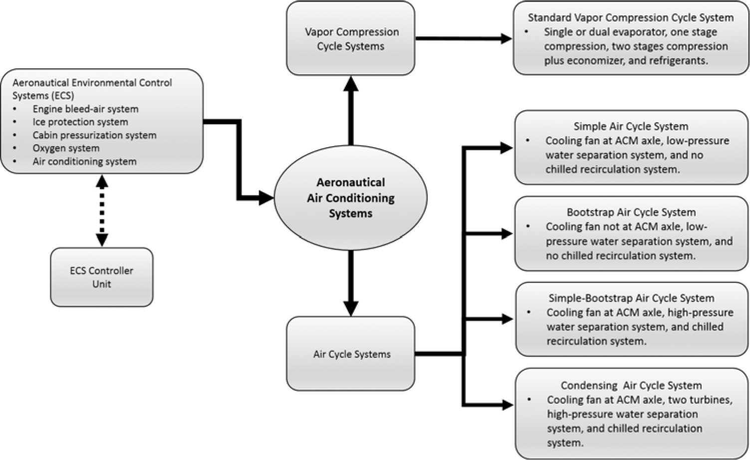
Figure 1. Overview of aeronautical air conditioning systems.
2.0 AERONAUTICAL ENVIRONMENTAL CONTROL SYSTEMS
The ambient conditions outside a commercial aircraft flying at high altitude and high speed, present without doubt, formidable challenges that need to be overcome so that occupants can reach their destination without even realizing how harsh atmospheric conditions can be. Moreover, besides the fact that inside an aircraft the occupants must find a habitable zone, the aircraft systems, including the ECS, need to operate according to their design conditions during the entire flight.
Environmental control systems are present in virtually all aerospace vehicles, whether for military or civil (commercial or executive) application, manned or unmanned, including fixed or rotary wing designs. This is because any vehicle of this nature operates under controlled parameters associated with, for instance, the temperature of avionics equipment, protection against ice formation on leading edges of the wings, pressurized airflow to the cabin, fresh air to occupants, cabin temperature and humidity, and emergency oxygen supply in case of cabin decompression.
In general, the source of energy for the wing anti-ice system is the main engine compressor (intermediate stages) bleed air, but new concepts are emerging, like electrically-powered carbon nanotube heaters installed in the leading edge of the aircraft semi-wings with good “proof of concept” results(Reference Affonso, da Silva, da Silva, Thomas, Kessler and Domingos7).
With regard to the engine bleed air system (EBAS), also known as the pneumatic system, a portion of the compressed air of the gas turbine engine is extracted and may be used as a power source for many systems, including: (a) air conditioning; (b) pressurization; (c) ice protection; (d) cross engine starting; (e) air turbine motors; (f) air-driven hydraulic pumps; (g) on-board inert gas generating systems (OBIGGS); (h) on-board oxygen generating systems (OBOGS); and other pneumatic power consumers, depending on the aircraft design(8).
In many cases, the temperature and pressure of the engine bleed air are far too high to be used by the ECS. Bleed air pressure and temperature in a military fighter aircraft can be in the region of 4,000kPa and 800K, respectively. This is sufficient to cause the ECS components to melt. The first task of the ECS is to reduce the pressure by means of a pressure regulating valve (PRV) and the temperature by means of a pre-cooler (PREC)(Reference Lawson, BLOCKLEY and SHYY3).
An important aspect of bleed air is that it acts as the main source of “fresh air” used to ventilate the aircraft compartments. If the EBAS is completely shut down, the only other possible source of fresh air (besides the oxygen system) comes from the ram air ventilation system (part of the air conditioning system design), which consists of a specially designed circuit that conveys fresh air from ram air inside the aircraft zones. The nominal performance of the ram air ventilation system occurs at 10,000ft (3,048m) by design, since this is an acceptable flight level for unpressurized aircraft (abnormal operation) without compromising human survivability. At this flight level, the effects of a deficiency in the oxygen supply to the body and brain tissues (hypoxia) is not pronounced and a safe flight is possible(Reference Moir and Seabridge9).
During a rapid decompression from complete loss of inflow and subsequent emergency descent (to FL100), cabin pressure will approach ambient pressure(10). If the airplane is equipped with an emergency ram air ventilation system (RAVS), the cabin pressure will be maintained at a positive gauge pressure approximately equal to the aerodynamic pressure minus the ram air inlet, ducts, and outflow valve (OFV) pressure losses.
At high latitude and altitude flights, ozone can be brought inside the cabin by the EBAS, which can cause airway irritation and reduced lung function(11). To cope with these health effects, the EBAS may include an ozone converter (as optional) for aircraft intended to operate in such environments.
Acceptable levels of ozone inside the cabin can peak at 0.25 parts per million (ppm) and on average should not exceed 0.1ppm. In the atmosphere, aircraft can encounter ozone concentrations as high as 0.8ppm(Reference Lawson, BLOCKLEY and SHYY3).
In addition to the EBAS, the aircraft generally has an auxiliary power unit (APU), which is basically a separate (smaller) gas turbine engine fitted to the aircraft designed to provide: (a) compressed air for engine starting, the air conditioning system (ACS) and the cabin pressure control system (CPCS), when the main pneumatic source is not available or during special aircraft operating conditions; (b) electrical power from shaft-driven generators; and (c) hydraulic power for various applications.
APUs are generally used in ground operations in cases where the main aircraft engines are off and no ground support equipment (GSE) is available as a high pressure pneumatic ground cart or ground power unit (GPU).
The APU is used for many purposes, for instance: (a) to run the air cycle air conditioning system, during ground operations (pull-down), take-off, landing, and even up to 15,000ft (4,572m); (b) to start an engine at up to 20,000ft (6,096m); and (c) to replace a faulty main engine electrical generator up to 41,000ft (12,497m) of altitude.
The CPCS continuously monitors the aircraft altitude and flight modes (take-off, climb, cruise, descent and holding) and controls the air mass flow that exits the pressurized cabin by means of an OFV to maintain the cabin pressure within acceptable levels for passengers and crew members during the entire flight(Reference Hunt, Reid, Space, Tilton, Hunt, Reid, Space and Tilton12). The cabin air inflow, as previously mentioned, is provided by the EBAS.
The CPCS is responsible for constantly determining and adjusting the cabin altitude (pressure altitude) with respect to the aircraft altitude, to guarantee the required comfort inside the cabin. This kind of “map” is the pressurization schedule(13). A typical commercial aircraft pressurization schedule can be found in Moir and Seabridge(Reference Moir and Seabridge9).
The human physiology is such that for survival humans must have a gaseous oxygen supply available(13). In addition, oxygen levels must be at a minimum concentration or vapor partial pressure to avoid symptoms related to lack of oxygen (hypoxia). Oxygen at a reduced partial pressure can seriously compromise human performance and, if acceptable conditions are not re-established in time, this may compromise the flight safety. In this regard, supplemental oxygen systems are designed to provide a secondary source of oxygen, in case the primary source is compromised for any reason.
Although the oxygen that reaches the aircraft occupants is always gaseous, its storage and distribution may be in the form of high pressure gaseous, liquid or chemical block sources or it can be concentrated from air by the OBOGS for use in aircraft systems. The most common oxygen sources for commercial airliners are chemical oxygen and gaseous systems(Reference Lawson, BLOCKLEY and SHYY3).
Ice and rain protection systems are a relatively extensive subject in the context of the ECS.
Many configurations are available depending on the type of application and the power source (pneumatic or electric). In addition, the ice and rain protection can be separated into in-flight and ground operations, where ice formation is prevented or eliminated making use of different types of equipment.
Regarding ice and rain protection during a flight, the methods currently in use are: (a) anti-icing systems in which ice formation is prevented from occurring; and (b) de-ice systems in which ice is eliminated in cycles during the system operation; in this case, ice formation to a certain extent is allowed until it is eliminated in a cyclic pattern.
Anti-icing systems can be divided into: (a) hot bleed air; (b) electric heat; (c) exhaust heat; and (d) freezing point depressants (anti-icing fluids). De-icing systems can be divided into: (a) pneumatic boots; (b) electro-impulsive; (c) electro-expulsive; (d) pneumatic-impulsive; (e) microwave systems; (f) freezing point depressants; and (g) hot bleed air(Reference Heinrich, Ross, Zumwalt, Provorse and Padmanabhan14).
Airborne air conditioning systems, another important integrant of aeronautical environmental control systems, will be discussed in the following sections.
Lastly, the ECS controller unit integrates all of the ECS control functions in a single box, although some designs may include more than one unit to control the ECS functions.
3.0 AERONAUTICAL AIR CONDITIONING SYSTEMS
The following sections provide a review of vapor compression cycle systems as well as air cycle systems suitable for aeronautical applications.
3.1 Vapor compression cycle systems
Vapor compression cycle systems are based on the closed vapor compression refrigeration cycle, which is a modified Rankine cycle operating in reverse(Reference Çengel and Boles15). The working fluid is a chemical refrigerant that changes phase during the cycle processes.
In a vapor compression cycle air conditioning system, the main power source comes from an electric motor-driven refrigerant compressor, which provides power to run the refrigeration cycle. In this cycle, the working fluid is no longer air but rather a chemical refrigerant, thus no fresh air is provided by the air conditioning system (in contrast to the air cycle) and therefore, fresh air must be supplied by the EBAS that feeds the CPCS. Typically, a vapor compression cycle system “re-circulates” air from the cabin and cockpit to remove the required heat load.
3.1.1 Standard vapor compression cycle
Figure 2 shows a schematic of a typical vapor compression cycle system with two evaporators. In a standard vapor compression cycle system, for a sub-sonic airplane, the main components are: compressor (C), receiver filter drier (RECFD), evaporator (EVAP), thermostatic expansion valve (TXV), condenser (CON), ground cooling fan (GCF) and recirculation fan (RF), that promotes the air recirculation through the evaporator. The ground cooling fan promotes the air flow across the condenser during ground operations when ram air is not available.
In the vapor compression cycle air conditioning system configuration, most aircraft manufacturers make use of two evaporators (one for the cockpit and one for the cabin), a swash plate compressor type unit with variable displacement driven by a brushless DC electric motor, and R134a as the refrigerant. This applies to the following cases: Eclipse 500 (Eclipse Aviation); Citation Mustang; Citation CJ1 (Cessna); Phenom 100; Phenom 300 (Embraer); and Honda Jet (Honda Aircraft Company). Some configurations may also involve the use of an economizer and a second-stage compression in order to improve the coefficient of performance (COP) values, but in this case, the weight penalty may be an issue. Modern designs may use a scroll compressor as well as a micro-channel heat exchanger, specially for the condenser since there is no formation of condensate on its fins which may be a issue for this type of heat exchanger. With regard to aeronautical applications, for a small jet engine aircraft, a reasonable COP value would be between 3 and 4.
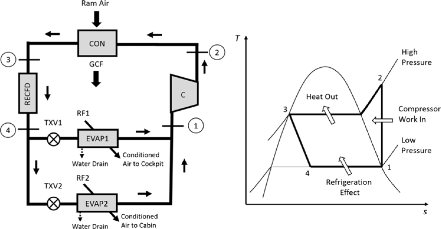
Figure 2. Schematic and the ideal T-s diagram of an aeronautical vapor-compression cycle system.
The power source for vapor compression cycle systems is typically electricity and ambient air is generally used as a heat-sink. The refrigerant compressor and fans for the air supply are typically driven by an electric motor but geared shafts, hydraulic motors and air motors may also be used.
Vapor compression cycle systems are relatively complex in terms of design and operation, especially if they make use of modern variable displacement compressors, brushless DC electric motors and controllers. Some problems are associated with vapor compression cycle systems under extreme environmental conditions, like the effects of a rapid change in ambient temperature and pressure, heat load, control of the cycle pressure during condensation, and vibration levels(Reference Gurney16).
For aeronautical purposes, it is important to keep the whole system as lightweight as possible and thus careful design of the system components is paramount. In this regard, the airflow level throughout the condenser provided by the GCF during ground operations or the ram air circuit are notable examples. It can be demonstrated that the cycle COP increases and compressor power is reduced on increasing the condenser cooling air flow. However, this effect is observed only up to a certain value for the condenser airflow(Reference Kang, Jaehyeok and Kim17). Above this value, an increase in the condenser airflow is not efficient and may cause the GCF to be oversized, which ultimately will increase costs, weight, and GCF noise levels, which is undesirable.
A relatively advanced vapor compression cycle system controls the compressor capacity by means of its suction pressure (the variable displacement compressor mechanically controls the suction pressure at a certain value) and evaporator superheat (TXVs control the evaporator outlet refrigerant superheat).
Proper selection of the refrigerant fluid for a specific system is vital for efficient, safe, and reliable operation of the designed system(18). A typical environmentally-friendly refrigerant with zero ozone depletion potential (ODP) that is suitable for aeronautical applications is R134a. However, its global warming potential (GWP) is rated at 1300(Reference Tamura, Yakumaru and Nishiwaki19,Reference Verma, Satsangi and Chaturani20) .
There has been considerable effort in the industry directed towards the use of low GWP refrigerants in current and new vapor compression cycle systems. Potential replacements for R134a (COP of 3.315) include the refrigerant RE170 (COP of 3.523) and other eco-friendly refrigerants like HC600a, HC1270, HC290, HFC32 and HFC152a(Reference Baskaran and Koshy Mathews21).
3.2 Air cycle systems
Aeronautical air conditioning systems are based on the open reversed Brayton cycle. The working fluid is atmospheric air and there is no phase change during the thermodynamic cycle.
The most common air conditioning system used in both military and civil aviation is based on the air cycle system. In this case, the main power source is the compressed air extracted from the initial stages of the aircraft engines, more specifically, air from the EBAS. A schematic of the air cycle ACS is shown in Fig. 3.
Cold air from both air conditioning units (ACU1 and ACU2) is mixed with recirculated air from conditioned areas inside the pre-mixer (PM) and provided to conditioned cabins by means of the air conditioning distribution system which includes a mixing manifold (MM). A zone temperature sensor (ZTS) is used for each conditioned zone to monitor the desired temperature. Fine temperature control is obtained by the trim air system, which is responsible for heating the inlet air for the conditioned zones as required, by means of trim air valves (TAVs), as shown in Fig. 3 based on ASHRAE(2).
The pressure of the bleed air available for the TAVs is regulated by the trim air pressure regulating valve (TAPRV) and as a result the airflow is choked at the TAPRV, which is in a non-pressurized zone, instead of at the TAVs, which are in a pressurized zone. This reduces cabin noise levels due to trim air flow, and in this sense a muffler downstream each TAV may also be used to improve cabin comfort. In addition, a trim air check valve (TACKV) shall be used depending on safety margins of the design.
The ram air circuit through the ACU provides air as a heat sink source for the air cycle and may be regulated by means of a ram air regulating valve (RARV), downstream the ram air cooling circuit. This circuit should not be mistaken for the emergency ram air circuit, which includes the emergency ram air valve (ERAV) and the emergency ram air check valve (ERACKV), which provides fresh air to the cabin if there is a complete loss of the engine bleed air inflow to the cabin. Dividing the non-pressurized from the pressurized zone is the bulkhead check valve (BCKV).
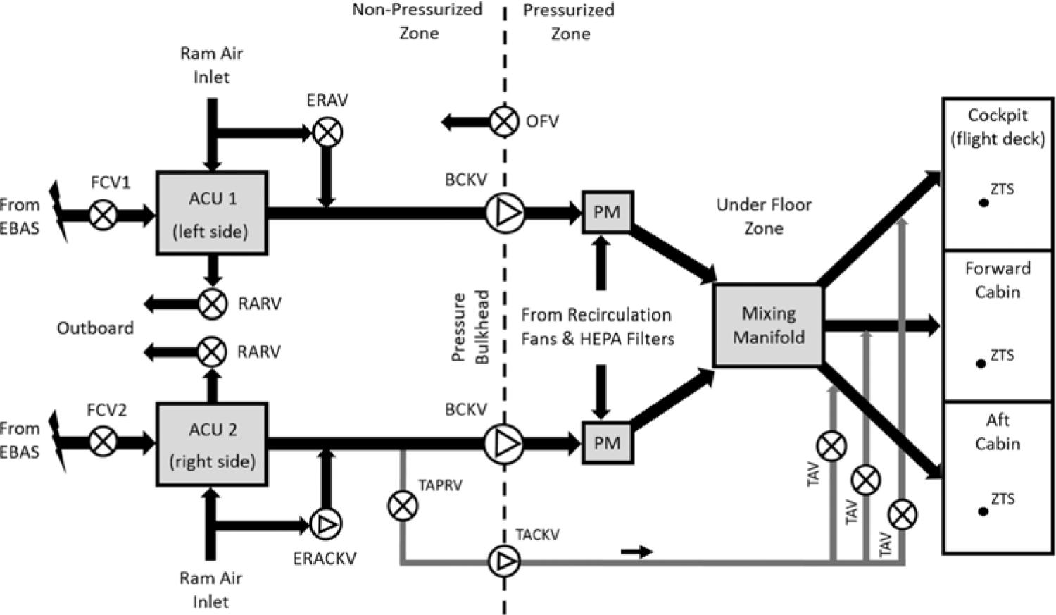
Figure 3. Schematic of a typical commercial aircraft (air cycle) air conditioning system.
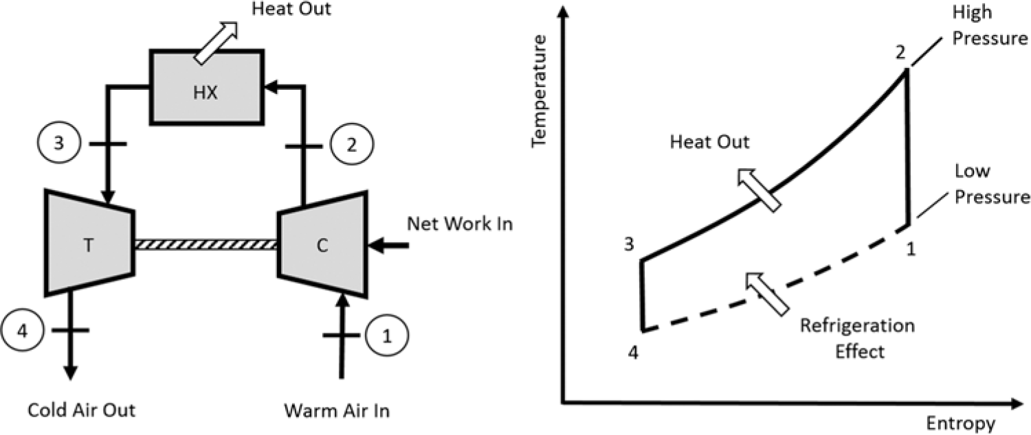
Figure 4. Basic ideal aircraft air cycle refrigeration system.
The main energy source for air conditioning systems based on gas (air) refrigeration cycle units is the compressed air from the gas turbine engine, which is provided to the ACS by the EBAS. The amount of bleed air mass flow that passes to each ACU is controlled by the flow control valve (FCV). Air leaves cabin through the OFV.
As previously mentioned, air cycle refrigeration systems for aeronautical purposes basically operate in an open reversed Brayton (or Joule) cycle(Reference Çengel and Boles15). Figure 4 shows a basic ideal aircraft (air) refrigeration cycle. The ambient air (working fluid) is compressed by the main engine compressor and represents the power input for the air cycle air conditioning system. The external aircraft environment (ambient air) is typically used as the heat sink, but some designs may use fuel as the heat sink.
In a ram air coolant-based system the air may be forced through a heat exchanger by means of a fan or a jet pump (this is more common in military applications). In a fuel coolant-based system, fuel is forced through a heat exchanger by means of a pump(Reference Lawson, BLOCKLEY and SHYY3).
There are limitations associated with air cycle units, because these configurations need a high cooling capacity, requiring large airflow levels from ram air and large-diameter ducts, leading to strong ram air drag(22). In addition, as the engine bleed air requirements increase so does the main gas turbine engine fuel consumption, which incurs fuel consumption penalties.
Open-loop air cycle systems can be responsible for a 5% increase in fuel consumption associated with providing engine bleed air to overcome the ram air drag and to power the ECS and related sub-systems.(23)
Several air cycle system configurations for aeronautical purposes are available and the selection is dependent on the type of application. The most common configurations are: simple cycle, bootstrap cycle, simple/bootstrap cycle (3-wheel), and condensing cycle (4-wheel).
3.2.1 Simple cycle
The most common simple air cycle system based on engine bleed air supply is basically a Brayton (or Joule) open cycle operating in reverse, comprised of a high-pressure air source, a heat exchanger, a fan to increase the cooling air flow through a heat exchanger, and a high-speed turbine. This configuration allows the system to provide a certain degree of cooling air during ground operations, since the fan can provide cooling ambient air flow to the heat exchanger when ram air is absent or during low speed flight.
Simple air cycle air conditioning systems are commonly used for military aircraft (due to the availability of high-pressure engine bleed air) and a typical COP value of 1.2 is achieved for aircraft flying at Mach 1.5 in the tropopause region. The cooling capacity is a direct function of the pressure ratio(22).
Figure 5 shows a typical configuration of a simple air cycle when the power source is provided by the main engine primary compressor (PC) bleed air. In addition, the schematic shows the diffuser (D), engine turbine (ET) and nozzle (N) of the main engine.
Hot bleed air from the engine PC passes through a PREC heat exchanger that uses ram air as a heat sink to limit the bleed air temperature entering the simple cycle ACU.
The bleed air also passes through a PRV and a FCV, which controls the mass flow to the simple cycle ACU, before it enters the simple cycle heat exchanger (HX) and turbine (T). A temperature control valve (TCV) is used to adjust the conditioned air temperature that is provided to the cabin.
Ram air is also used as a heat sink for the simple cycle HX and on the ground a cooling fan (F) guarantees a minimum cooling mass flow for the HX. Also, a check valve (CV) is used to avoid reverse flow to the cooling circuit.
The cooling fan is generally installed downstream of the heat exchanger, providing air flow through suction, to avoid an additional increase in the temperature due to the air compression, which would negatively influence the heat exchanger effectiveness(Reference ARORA24). An example of the pressure and temperature variation in a simple cycle of the engine bleed air prior to the HX and after the T can be found in Lawson(Reference Lawson, BLOCKLEY and SHYY3).
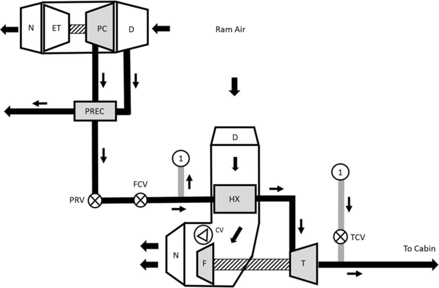
Figure 5. Simple (open) air cycle.
3.2.2 Bootstrap cycle
In the bootstrap cycle architecture, the turbine drives a compressor instead of a cooling air fan as in a simple air cycle. In this case, a secondary heat exchanger (SHX) or intercooler is required to reduce the temperature of the air coming from the compressor and entering the turbine. Once again, ambient air is used as a heat sink.
Figure 6 shows a schematic of a bootstrap cycle in which a secondary compressor (SC) and a SHX have been included in addition to the primary heat exchanger (PHX). The cooling fan in this type of arrangement is driven by an electric motor (EM).
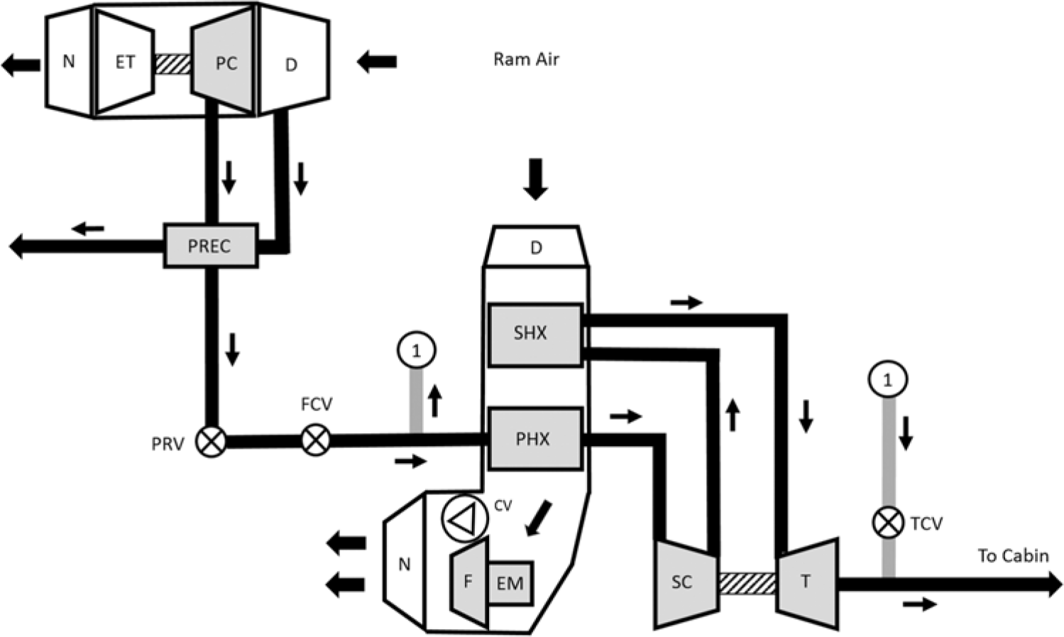
Figure 6. Bootstrap cycle.
In general, an electric motor-driven fan is used to accelerate the air in the heat exchangers to help the system to provide cooling air during operation on the ground or at low speeds, when the ram air flow is limited. An alternative to the electric fan is a jet pump (e.g., for a military strike aircraft)(Reference Shetty, Lawson and Shahneh25).
Bootstrap air cycle air conditioning systems are also commonly used for military aircraft, in cases where the available engine bleed air pressure levels are limited. A typical COP value of 1.0 is achieved for aircraft flying at Mach 1.5 in the region of the tropopause(22).
According to Moir and Seabridge(Reference Moir and Seabridge9), there are two variations of the bootstrap cycle, called the reversed flow bootstrap cycle and the ram air-powered reversed bootstrap cycle. The term ‘reversed’ is used because the charge air passes through the air cycle machine (ACM) turbine prior to the compressor. The reversed bootstrap makes use of a regenerative heat exchanger to cool the turbine inlet air and a heat load removal system (for the air downstream of the turbine) may be used to remove the heat load from the radar system. After the ram air-powered reversed bootstrap cycle, the air passes directly to the turbine, then to a heat load removal system and the compressor before going outboard. In this system, cooling is a problem on the ground and in low-speed flight mode, therefore it is typically used as a standalone cooling system for equipment that is operated during a flight.
3.2.3 Simple/bootstrap (3-wheel) cycle
The simple-bootstrap cycle, or simply 3-wheel cycle, is a combination of the simple cycle and the bootstrap cycle. It incorporates both the simple cycle cooling fan and the bootstrap cycle secondary compressor. Therefore, the turbine shaft drives the secondary compressor as well as the cooling fan; hence, it is also known as the three-wheel air cycle machine. As previously mentioned, the term air cycle machine is used to refer to the turbine, secondary compressor, and fan in a single shaft. The schematic in Fig. 7 shows a simple/bootstrap cycle.

Figure 7. Schematic of a simple/bootstrap cycle.
Typical COP values for the simple/bootstrap cycles for a commercial aircraft may range from 0.17 to 0.43, depending on the cycle arrangement, as discussed in the following sections.
3.2.3.1 Air cycle water separation systems
Basically, in an air cycle unit there are two types of water separation systems, namely: (a) low pressure water separation (LPWS) system; and (b) high pressure water separation (HPWS) system.
In a LPWS system, the water extractor (WE) is located downstream of the cooling turbine (T), driven by the ACM axle, that expands air from a HX, which means that it operates at a relatively “low pressure”. Moisture is condensed right after the cooling turbine due to the expansion process. This process results in the moisture being in the form of fog or extremely small water droplets. In this case the WE makes use of a coalescing device in order to remove the condensate and prevent it from entering the cabin. The dry bulb temperature exiting the turbine is controlled by the TCV using bleed air from the EBAS and, in general, must be limited to a minimum of 1.7°C, or its equivalent dry air rated (DAR) temperature, in order to avoid ice formation, which can lead to clogging of the coalescing device. As in the Boeing 737, the coalescer bag is made of polyester and if it is dirty or full it needs to be replaced. In addition, if the coalescer bag is clogged, there is a mechanism that mechanically bypasses the water separation system in that aircraft.
Periodic maintenance is required for the coalescing element (bag) since it needs to be regularly cleaned to ensure its efficiency and to avoid problems the maintenance time interval must be adjusted if the aircraft operates in a region where bleed air contaminants, such as sand and dust, are present. The schematic in Fig. 8 shows a low-pressure water separation system.

Figure 8. Schematic of a low pressure water separation system.
In an HPWS system, the WE is located upstream of the cooling turbine (T), which means that it operates at a relatively high pressure. Furthermore, regenerative heat exchangers are used to further reduce the air flow temperature downstream of the SHX. In this case, a condenser or both a condenser and a re-heater (REH) heat exchangers may also be used, depending on the configuration of the air cycle unit, to reduce even further the temperature of the air exiting the SHX. This is limited by the TCV whenever required.
In the process described above, due to the reduction in the condensing temperature, the condensation of moist air into liquid droplets that are sufficiently large so that a coalescing device (coalescer bag) is not required to collect and remove them from the air stream. In this case, an inertial WE is used.
The fact that there is no coalescing device in an HPWS system (with no icing problems causing the coalescer bag to clog) means that lower temperatures can be reached downstream of the cooling turbine and, consequently, for the same cooling capacity, lower air flow is required compared to the LPWS systems. Figure 9 shows a full-flow HPWS system, including a REH. A HPWS system configuration without a REH as well as a partial-flow configuration is also possible(26).

Figure 9. Schematic of a high pressure water separation system.

Figure 10. Simple bootstrap air cycle unit with high pressure water separation and chilled recirculation.
The water collected in the water separation systems, is usually “sprayed” upstream of the SHX of air cycle systems (when applicable) to increase the cycle efficiency, as shown in Fig. 10 in the next section. Reducing the ram air heat sink temperature increases the cycle efficiency. If there is too much water, there is an “overflow” port, which is a calibrated hole lin the upper part of the WE that drains water directly to the atmosphere, avoiding excessive water entering cabin.
Ice may form in the condenser of a high-pressure water separation system and thus the system includes a de-icing cycle. During the de-icing cycle, the TCV is opened for a limited time until ice on the condenser fins is melted. The de-icing cycle is either activated or de-activated based on the condenser pressure drop. Thus, in this case, there is a closed control loop involving the TCV and the condenser pressure drop.
Although the main disadvantage of a high-pressure water separation systems is the heavy weight, it has the benefits of no need for maintenance action and a high water removal efficiency.
The water sprayer (WS) can increase the cycle COP by roughly 4%, when there is enough free moisture leaving the WE and being sprayed upstream of the SHX. If the water sprayer becomes clogged, the condensate water level in the WE will increase to above the nominal value until it reaches an overflow port through which it is drained overboard to avoid excess water entering the cabin. This overflow port also increases the total bleed air leakage of the system, which can reach 5% of the total bleed air flow throughout the air cycle unit (from FCV to BCKV).
Some low-pressure water separation systems can also make use of a WS or some sort of water injection system upstream of the SHX to improve the cycle efficiency, but with limited pressure compared to the high-pressure water separation systems.
3.2.3.2 Air cycle recirculation systems
The recommended temperature range of air entering occupied compartments in a commercial aircraft, during normal operation, is not less than 2°C (36°F) or more than 71°C (160°F)(26).
As previously mentioned, for an air cycle unit with a low-pressure water separation system, the temperature downstream of the cooling turbine, for maximum cooling purposes, is around 1.7°C (35.1°F). In this case, the requirement of 2°C (36°F), mentioned above for air entering the cabin, can be easily met since the temperature can be adjusted by heat transferred through the cooling duct to the cabin zone (through the cabin distribution duct system), which normally occurs because the thermal insulation of the ducts is not completely effective.
When the air cycle unit operates with a high-pressure water separation system, temperatures downstream of the cooling turbine can reach levels of around −13.8°C (7.2°F), for maximum cooling purposes(Reference De Francesco27). In this case, in order to guarantee that the temperature of the cooled air entering the occupied zones is within the recommended limits, a recirculation system can be implemented, increasing the total air flow to the cabin as well as its temperature, respecting the minimum recommended temperature of 2°C (36°F) for air entering the cabin, so that the air cycle capacity can be fully used without limiting the temperature leaving the cooling turbine and consequently not using the total available cooling capacity of the system. As a reference, it is common that the recirculated air mass flow represents around 50% of the total air mass flow entering the cabin in a chilled recirculation system, but this can vary depending on the design criteria. The minimum fresh air mass flow required to the cabin has priority over the level of recirculated air mass flow.
The schematic in Fig. 10 shows a simple-bootstrap cycle with a HPWS system, which includes a WS and chilled recirculation characterized by the PM downstream of the condenser. This promotes the adiabatic mixture of the turbine cold outlet air with air coming from the conditioned zone (cabin) by means of a recirculation fan and an upstream high efficiency particulate air (HEPA) filter. Some configurations including a PM upstream the condenser as well as a compressor recirculation (shoestring) cycle are also possible(26).
Cabin air recirculation systems for commercial aircraft usually employ a HEPA filter upstream of each recirculation fan, namely left-hand and right-hand recirculation fans.
Figure 11 shows a simplified thermodynamic diagram for a simple/bootstrap cycle with a high-pressure water separation system. The heat exchangers have no pressure drop, the isobars are straight, rather than curved, and there are compression and expansion processes. The PM effect is also shown.

Figure 11. Simplified T-s diagram for a simple/bootstrap cycle.
It is important to note that the design of an aeronautical air conditioning system is a complex task subject to optimization. Thermo-economic optimization of an aeronautical air conditioning system has been proposed and the best engine bleed air pressure level was determined for a cost-efficient design(Reference Leo and Pérez-Grande28).
Moreover, based on the thermodynamic optimization of a bootstrap cycle it is possible to reach an ideal cabin inlet temperature in order to guide the system design engineer during the preliminary or conceptual design phase of an aeronautical air conditioning system to pursue a more realistic design(Reference Ordonez and Bejan29).
Some bootstrap systems are powered by high-pressure engine bleed air and make use of ambient air (ram air) and/or the on-board fuel as the heat sink. Hybrid systems can also be used (vapor compression cycle and air cycle), applying the same approach in a more integrated environmental control system, which can significantly reduce the engine bleed-air consumption as well as heat sink demand, both of which are very important in terms of achieving an aircraft that is energy-efficient(Reference Lui, Quan and Wong30).
3.2.4 Condensing (4-wheel) cycle
The condensing cycle can be seen as an improvement to 3-wheel systems, in which an additional turbine (T2) has been included in the cycle as well as an altitude vent valve (AVV), a condenser low limit valve (CLLV), an additional check valve (CV2), and a second-stage turbine bypass valve (SSTBV).
The CLLV is used to maintain the condenser inlet temperature at above freezing levels. The SSTBV is operated in cases of a heating requirement or to allow the minimum fresh air mass flow to the cabin to be achieved. The AVV is also used to provide the minimum fresh air mass flow to the cabin. In addition, this valve is related to ram air savings during high altitude flight. The AVV essentially makes the cycle operate in this mode as a 3-wheel cycle with a large turbine nozzle area(Reference De Francesco27).
Figure 12 shows a schematic of a condensing cycle (4-wheel), with additional components in comparison to the 3-wheel cycle architecture.

Figure 12. Schematic detailing the condensing cycle system.
A condenser and a WE are used in the cycle in a HPWS system. Also, a REH is used to guarantee acceptable levels of liquid water to feed into the first turbine.
Typical COP values for a condensing cycle for a commercial aircraft may range from 0.33 to 0.44. Condensing (4-wheel) cycles are commonly used in commercial aviation and produce colder turbine discharge temperatures than simple-bootstrap cycles(Reference De Francesco27).
4.0 COMPARISON BETWEEN VAPOR CYCLE AND AIR CYCLE SYSTEMS
In general, vapor compression cycle refrigeration systems provide a much higher COP than air cycle systems. Due to the simplicity of the air cycle systems, they tend to be lighter than vapor compression cycle systems for the same cooling capacity.
Vapor compression cycle refrigeration systems are the classical choice for small aircraft in which the availability of engine bleed air, required for air cycle systems, is limited to the point that the use of air cycle systems is not possible. In addition, for small aircraft with relatively high refrigeration loads, a more efficient refrigeration system (higher COP) is a possible solution for the design and in this case a vapor compression cycle system can be used. In general, the COP for a vapor compression cycle system is five times the COP of a comparable closed-loop air cycle system(Reference Moir and Seabridge9).
Air cycle systems are generally powered by compressed air, while vapor compression cycle systems are shaft powered or, more commonly, electrically powered. In this case, care must be taken during the design phase because bleed air-powered systems have a relatively greater impact on the specific fuel consumption than shaft-powered extraction.
For relatively larger aircraft, the classical choice for the air conditioning system concept is based on air cycle units because the use of a bleed air-powered system is less detrimental to the performance compared with small aircraft with small engines. Combined solutions, making use of air cycle and vapor compression cycle units, are also possible in this case.
Air cycle systems provide, in addition to the cooling air for the cabin, the benefit of air supply for pressurization and ventilation (fresh air). In cases where there is a shortage of compressed air, that must be bled from the engines to run an air cycle unit and achieve the required cooling capacity, vapor compression cycle systems constitute an appropriate alternative.
In the case of larger aircraft, compressed bleed air may be readily available at the required level and in this case air cycle systems are more suitable due to their simplicity and weight savings, even though they present a lower COP and will require more power to deliver the same cooling capacity, compared to vapor compression cycle systems.
When the required fresh airflow is lower compared to the required recirculation air (from the cabin), vapor compression cycle systems are more suitable, while for other cases air cycle systems are used(22).
Vapor compression cycle systems are recommended when there is a need for full recirculation, i.e., no fresh air supply is required. This may be the case when the air conditioning unit is dedicated to equipment cooling only, which is more common in military than in commercial applications.
Air cycle systems are usually associated with higher noise levels caused by high rotational speed of the ACM, which requires noise treatment, accomplished using mufflers downstream of the air cycle unit airflow ducts. The ACM is the commonly used term that encompasses the cooling fan, turbine and the secondary compressor in a 3-wheel ACU. In a 4-wheel ACU an additional turbine is used. These components lie along the same rotating axis.
Mufflers are installed in each air duct branch that enters the cabin zone, so that noise level requirements inside the cabin may be achieved. In addition, mufflers must be installed downstream of the air cycle unit ram air path, in order to satisfy external noise level requirements during ground operations.
Vapor compression cycle systems present relatively larger ground cooling capacity, allowing better pull-down capability. However, these systems with high capacity are associated with high complexity due to the need to control the variable displacement high power compressor. The controller for the compressor in this case is complex and susceptible to overheating, an issue that, if not identified and addressed at the development phase, may cause premature failure. This can lead to low equipment mean time between failures (MTBF) and costly corrections after aircraft entry into service.
One disadvantage of vapor compression cycle systems is that their heat sink temperature (for most of the refrigerants used) is considered to be unacceptably low, typically between 65°C (149°F) and 70°C (158°F), which means that the cycle can only reject heat to an ambient below this reference temperature and this could be a problem in certain areas of the world(Reference Moir and Seabridge9).
5.0 COMPARISON BETWEEN AIR CYCLE SYSTEMS
Simple cycles are typically used due to their simplicity and reliability, and their relatively low weight is also a key factor. The bootstrap cycle can be an option for aircraft operating at very high altitudes when the bleed air pressure from the engine compressor is too low. Moreover, because a relatively low flow passes through the turbine, the turbine wheel diameter and nozzle throat areas must be small, requiring high rotational speed operation to achieve the required temperature and pressure ratios. The turbine rotational speed, for instance, can range from approximately 17,000rpm to 57,000rpm, or reach even higher values, in a simple/bootstrap cycle.
The bootstrap cycle operating with ducted ram air as the heat sink (compressor to turbine inter-stage cooling) becomes suitable for flights at above Mach 1.2 at sea level(Reference Gabbay31). For regular commercial flights where velocities are subsonic at sea level, this limitation does not apply, and the bootstrap cycle is still of great relevance during the system selection process.
The bootstrap cycle is generally used in aircraft where available air pressure levels are limited because low pressure results in insufficient cooling when the simple cycle is used. This is because when a compressor (driven by the turbine) is used, it increases the pressure of the air supplied to the cooling turbine, which also increases both the turbine pressure ratio and the temperature drop across the turbine.
The simple/bootstrap cycle (3-wheel) offers some advantages over the simple cycle. During ground operations, full cooling capacity can be attained with the engines close to the minimum power, leading to lower engine noise levels as well as reduced wear and lower fuel consumption. Moreover, the simple/bootstrap cycle can deliver its full cooling capacity in cases where either a pneumatic ground cart or an APU is used, which cannot be achieved by a simple cycle system operating under the same conditions due to limitations in the pressure available to the air cycle. In addition, in contrast to the ACM of a simple cycle, the simple/bootstrap cycle ACM is not prone to overspeed because the compressor would absorb most of the turbine power(32).
The simple/bootstrap cycle (3-wheel configuration) presents advantages over the bootstrap cycle. It does not make use of a separate electrically or hydraulically driven fan to promote cooling air flow throughout the heat exchangers (ram air circuit); instead it incorporates the fan along the same axle as the turbine and compressor, which reduces the weight and improves the system reliability(32).
For current commercial applications, the classical choice for an air cycle air conditioning system is based on the simple/bootstrap cycle (3-wheel) with high pressure, water separation and chilled recirculation system.
The commonly cited advantages of the 4-wheel cycle over a 3-wheel cycle are basically: (a) lower system weight due to higher cycle efficiency; (b) improved moisture removal, due to the fact that in a 4-wheel system the moisture removal rate remains steadier for different operating points than in a 3-wheel system, which means that moisture is removed more efficiently in a 4-wheel system; (c) the condenser operates at temperatures above freezing, simplifying its design; and (d) ram air savings at high altitude, which basically translates into lower drag and consequently lower fuel consumption(Reference De Francesco27).
Table 1 provides information on the air cycle systems used for different types of aircraft, including the arrangement in terms of water separation and recirculation systems.
Table 1 Air cycle units used for different types of aircraft

6.0 CONCEPTUAL DESIGN PHASE & SYSTEM SELECTION CRITERIA
In the selection of the most appropriate air conditioning system for a commercial aircraft several factors are important. The following paragraphs summarize the most relevant aspects for selecting an air conditioning system that must be considered during the system conceptual design phase, namely: (a) performance; (b) aspects related to operational costs; (c) cabin comfort, temperature control, air quality, air distribution system and noise levels; (d) system function and reliability; and (e) fault diagnosis.
When selecting an air conditioning unit in the context of the environmental control system, exergy analysis is a valuable tool as it can highlight inefficiencies (irreversibilities) in the design and indicate how the system architecture could be changed to improve them(Reference Gandolfi, Pellegrini, Silva and Oliveira33).
The required capacity (heat load) of a system for both cooling and heating purposes must be clearly defined along with the air mass flow rate that will be used to run the ACM. Thus, based on these requirements it is possible to determine whether or not there is enough engine bleed air available for an air cycle unit to operate.
Cabin temperature control models can be used to improve the environmental control system design and performance (air conditioning unit included) under transient conditions. The objective is to improve the ECS controller response time and the cabin temperature control stability(Reference Romani and de Góes34).
It is important to mention that the same level of thermal comfort (thermal neutrality) for passengers inside the cabin of a commercial aircraft flying at high altitude can be achieved with a different cabin dry bulb temperature compared to the environment conditions inside a commercial building. This is because on a high-altitude flight, the cabin relative humidity is lower than on ground (between 15% and 20%), the mean radiant temperature is lower than the air temperature, and the air density is lower than 1.18kg/m3. In this case, for the same level of comfort on flights at high altitude, the dry bulb temperature inside the cabin should be higher than that in a commercial building environment(Reference Turcio and Neto35). This fact can directly affect the air conditioning design in terms of required heat load for both heating and cooling at different altitudes and consequently the selection of the air conditioning system.
If the design is based on a more electric aircraft (MEA), the approach described above is valid, but rather than bleeding compressed air from intermediate stages of the main engine compressor (conventional air conditioning system design), air is obtained from a dedicated electric motor-driven compressor (MEA concept).
It should be noted that the aircraft wing anti-ice or wing de-ice system, cabin pressurization system, and cabin ventilation (fresh air flow), which are all part of the ECS, compete with the air cycle air conditioning system for the air mass flow available during the design phase of the air conditioning system.
In general, anti-ice and de-ice systems, which are essentially engine bleed air consumers by nature, have priority over the definition of the air conditioning system. In this regard, if engine bleed air is not available for an air cycle air conditioning unit or the design does not account for an MEA concept, then the use of a vapor compression cycle system is the appropriate choice.
The required minimum air mass flow for cabin pressurization purposes also imposes a requirement in relation to sizing the air cycle unit, since it establishes what should be the minimum mass flow that an air cycle system should provide based on the cabin pressurization needs at different altitudes (aircraft operational envelope).
The minimum fresh air flow rate for each aircraft occupant is also an important requirement that may directly affect the design of an air cycle air conditioning system. As the cabin air inflow during normal aircraft operation must go through the air cycle unit, it is necessary to check if there will be situations in which the minimum required fresh air flow for occupants will not be achieved due to lack of EBAS pressure. This includes operations with both the main aircraft engine and APU bleed air flow.
If a vapor compression cycle unit is selected, an engine bleed air mass flow is also required so that the system can comply with heating requirements. Vapor refrigeration cycle systems for aircraft applications are only used for cooling purposes (as a refrigerator), and not as a heat pump for cabin heating purposes. In this case, a bleed air source is required for heating purposes because heating from a readily available bleed air source is a more efficient use of the available energy.
In general, for a small aircraft, there will not be enough engine bleed air available to run an air cycle unit and the common choice is to make use of a vapor compression cycle system.
The options available in the market for selecting air cycle systems are not seamless in terms of cooling capacity. This means that in some cases only one air cycle unit would satisfy all of the required cooling capacity, due to the lack of intermediate capacity options. In most cases, two air cycle units are used (two independent sources of inflow) per aircraft, on the left-hand and right-hand sides, due to safety considerations involving the loss of inflow that directly affects the aircraft pressurization system.
Should a vapor compression cycle system be selected, two independent sources of inflow are generally required to be available, as described above, since the vapor compression cycle system only recirculates the cabin air without providing fresh air for cabin ventilation.
Considering that vapor compression cycle systems are generally powered by an electric motor-driven compressor, in contrast to air cycle units that are powered pneumatically, electrical power consumption for a vapor compression cycle system is an important factor that must be carefully evaluated during the development phase.
Furthermore, system weight is critical especially when it comes to small aircraft and, as previously mentioned, vapor compression cycle systems are heavier than air cycle systems of equivalent cooling capacity, even though they present a much higher COP.
For ground operations, air cycle systems are operated in the great majority of cases by the APU bleed air source, instead of bleed air from the main engines of the aircraft. Therefore, the APU must be sized accordingly in order to allow a sufficient bleed mass flow for the air cycle operation. In fact, in relation to the cooling performance (pull-down) or heating performance (pull-up), the highest cooling and heating capacities are achieved when the APU is the bleed air source by design.
In cases where a vapor compression cycle system is used, pull-down can be accomplished by means of an electric GPU, which provides electrical power to the air conditioning system. In this case, a separate electric fan and ducting system may be used to provide a fresh air flow to the cabin.
The cabin air distribution system is responsible for distributing the air conditioning air flow that enters the cabin and ducts must be designed in order to avoid external condensation. This usually involves the use of thermal insulation, and any condensate that is formed needs to be collected by means of specific water drains at regular duct length sections, otherwise, if external condensation occurs, water drips may fall onto the passengers, which is not acceptable. Moreover, if condensation is not drained from inside the ducts it could accumulate in large amounts and, in some situations (e.g. during take-off) it may be driven to the back of the aircraft air distribution system (aft cabin region) and fall onto seated passengers; in this case not only as drips but as a stream of condensate.
Noise requirements also play a role during the selection phase and, as noted above, air cycle systems are associated with high noise levels, although vapor compression cycle systems may also present high noise levels during ground operations because on the ground a cooling fan must be used to provide air flow at ambient temperature (heat sink) to the vapor compression cycle system condenser (heat exchanger). In addition, the electrical motor that drives the compressor is an important source of noise that needs to be considered during the design phase in order to minimize the noise level inside the cabin.
Fuel consumption is also of key importance during the development phase of an air conditioning system and there are means to estimate the fuel weight penalty imposed on an aircraft, depending on the type of system selected(36).
Vapor compression cycle and air cycle systems operate based on a certain choice of heat sink. In this regard, for subsonic commercial airplanes, outside (ambient) air is the common choice for this task.
For aircraft operating at supersonic speeds, some factors may play a role in precluding either the use of the simple cycle or bootstrap cycle, namely: (a) little air is available at high altitudes; (b) high ram air temperatures limit the use of outside (ambient) air for heat sink purposes; and (c) the drag penalty caused by ram air at the heat exchangers is relevant. In this case, the use of regenerative air cycle systems is of great importance to overcome the problems associated with high speed and high altitude(22).
To improve the air conditioning unit reliability and performance, transient response as well as off-design performance must be considered(Reference Zhao, Hou, Zhu, Chen and Chen37).
The following tests related to performance and reliability can be applied during the development phase of an air cycle air conditioning unit:
(a) start/stop time and minimum number of cycles: this can reveal a potential problem of excess friction in the air bearing of the ACM (when applicable) that could damage it and make the unit operation unbalanced, which can cause the fan to touch the case or the ACM to brake;
(b) wind-milling effect: this is associated with the potential flow of ram air through the air path of the heat exchangers used to run the ACM, even when it is turned off, causing a problem in the ACM air bearing;
(c) overspeed of the ACM: when there is a fast fluctuation in the bleed air pressure, for instance, on opening of the bleed air high pressure valve, this can accelerate the ACM to speeds above its limit, should the flow control system not actuate fast enough to regulate the mass flow to the ACM, potentially causing damage to the unit;
(d) ACM fan surge: this may be caused by the obstruction of the ram airflow through the heat exchangers (cold side) and has the potential to stall the ACM fan and damage its blades.
Significant cooling problems are associated with flights at high speeds, despite the advantages of the aircraft refrigeration systems based on air cycle and vapor compression cycle systems(Reference Leech38). The heat sinks available for aircraft and missiles can vary, depending on the design requirements, as follows: (a) outside air: either from engine bleed air or ram air; (b) fuel: sensible heat or latent heat of vaporization of the fuel can be used; (c) expandable cooling medium: any pure substance carried in the aircraft for cooling purposes that is discharged overboard, for instance, water and liquid hydrogen; (d) heat capacity of aircraft structure: used for a short period; and (e) radiation to space: based on the very low temperature of outer space(22). A more in-depth study of aircraft refrigeration systems for supersonic aircraft is outside the scope of this paper. For commercial subsonic aircraft, ram air is used as a heat sink.
It is important to evaluate the effects of coupling between the aircraft main engines, engine bleed-air system, and the air cycle air conditioning unit in the early stage of the design phase. Thermal demands (heat and power loads) are greatly influenced by the aircraft speed and can cause, for instance, a significant reduction in the range should the ACM be running at maximum capacity(Reference Allison, Alyanak and Shimmin39).
The ECS is one of the main aircraft sub-systems that need to be evaluated during the conceptual design phase, since it has a strong influence on and interaction with other aircraft systems, greatly penalizing the propulsive system(Reference Chakraborty40).
According to Wright(Reference Wright, Andrews and Sabir6), major aircraft manufacturers and a United Kingdom airline have recently indicated that the air conditioning system overheat causes regular failures under specific operational conditions, which considerably affects the aircraft dispatch reliability. The cited author produced a review on known pollutants at airfields and analysed the potential use of electrostatic filtering as a solution to prevent fouling on the aircraft air conditioning unit heat exchangers due to airborne particulates.
According to statistics related to civil transport aviation, an air conditioning system based on a 3-wheel ACM with a low pressure water separation system or a 3-wheel ACM with high pressure water separation system are the most common choices for the 150-seat airliners(Reference Peng41).
During the conceptual design phase, the key drivers are system weight, maintenance cost, total cost of ownership (TCO), fuel cost associated with the design concept, logistics, and performance requirements based on different missions. TCO is the main driving factor in most of the programs and includes both, acquisition and operating costs. A TCO analysis is generally used to assess the viability of the capital investment. In order to minimize total acquisition costs, the ECS is generally purchased as a package containing as many sub-systems as is practical. Optimization of the life cycle costs (LCC) should be done at an early stage of the program. The best tool for estimation of the life cycle cost is a system design trade-off study, including the major impact of the ECS on the entire aircraft system during the total lifetime. Appropriate aircraft performance analysis should be conducted for trade-off studies of various ECS configurations, including the air conditioning system.
Wagner(Reference Wagner42) discussed the concept of the design of the life cycle cost (DTLC) of military aircraft, applied to propulsion sub-systems. The paper describes the resources necessary for DTLC during various engine life cycles. The results suggest that aircraft engine DTLC pays off by allowing a reduced LCC and lower lifetime fuel consumption. In addition, attention must be given to: (a) the effect of maintenance due to design decisions; (b) trade-offs associated with LCC, considering cost, weight, and system complexity versus maintenance man-hour savings; (c) aircraft-sizing missions that can push designs beyond cost-effective limits; (d) trade-offs involving fleet sizes, maintenance costs and over-utilization.
Eckels(Reference Eckels43) proposed a design methodology for civil transport aircraft considering market requirements and configuration development, which considers: (a) airplane range requirements; (b) technology level; (c) passenger amenity level; (d) configuration sizing; and (e) configuration optimization. The cited author concluded that design considerations involve more than drag, weight and thrust. Designers must understand the impact of passenger appeal, maintenance costs and airport compatibility as well as development costs associated with the configuration as the design evolves.
Cavalcanti(Reference Cavalcanti and de Andrade44) performed a comparative study between a conventional air cycle air conditioning unit based on a 3-wheel air cycle machine with a low pressure water separation system and a more electric aircraft (MEA) architecture that makes use of an electrically-driven compressor to provide compressed air to run the air conditioning ACM instead of air bled from the aircraft engine compressor. The results showed that the direct operating costs (DOC) of an MEA can be reduced by 14% compared to a conventional architecture of the air conditioning system.
SAE AIR1812B(23) provides information on the life cycle cost elements defined from the initial design phase through operational use, as well as key ECS cost factors. It also provides information on primary factors affecting ECS costs and how ECS designs can affect the overall aircraft cost. Life cycle costs for ECS are divided into three categories: (a) research, development, testing and evaluation; (b) procurement; (c) operations and support. To exemplify the importance of the ECS life cycle cost, two thirds of the ECS life cycle cost is related to operational and support costs, while procurement and development costs account for the remaining third.
Puttini(Reference Puttini45) discussed the correlation of integrated vehicle health management (IVHM) as an emerging aerospace discipline and the Big Data paradigm, which is greatly discussed in the information technology industry. He also proposed how the aircraft design process can be modified to incorporate IVHM trade studies that are detailed enough to allow companies to evaluate development costs related to savings on operations, sustaining efforts, and long-term maintenance.
When it comes to airline costs associated with maintenance, repair and overhaul (MRO), the value is around 9% of the annual operating cost, following closely behind fuel and labour costs, respectively. In order to reduce the operating costs, airline companies are outsourcing MRO activities. By doing so, the company can focus on its high value-added services and use the savings generated in other areas. It is estimated that from the mid-1990s to 2012, the percentage of outsourcing has increased from 25% to around 70% of maintenance activities(Reference Qin, Wang, Chan, Chung and Qu46). Fuel costs can reach 40% of an airline annual operating cost. Moreover, according to Knotts(Reference Knotts47), aircraft maintenance downtime and maintenance activity durations associated with man-hour expenses are very important factors that contribute to two kingpins of airline and civil aircraft performance: dispatch reliability and maintenance costs. The cited author also offers a means to provide timely and cost-effective fault diagnosis.
Leão et al.(Reference Leão, Fitzgibbon, Puttini and de Melo48) presented a methodology for cost-benefit analysis based on the use of prognostics and heath management (PHM) for legacy (existing) commercial aircraft. The methodology considers the characteristics of aircraft operation and evaluates the feasibility of applying PHM technology to these platforms. The PHM technology advocates numerous benefits, such as improved troubleshooting, maintenance schedules for condition-based parts, and logistic supply chain optimization. A knowledge of this methodology could be used to improve the aircraft design during the conceptual design phase, creating provisions for the use of this technology in the future.
A more in-depth approach to ECS life cycle costs is outside the scope of this review, since the intention here is to focus on ECS air conditioning architectures. Information regarding operations and support costs as well as procurement, research, development, test and evaluation is generally classed as proprietary information and is not available in the open literature. To obtain further details regarding the factors that affect the ECS life cycle costs, the reader is referred to SAE AIR1812B(23).
Ma et al.(Reference Ma, Lu and Liu49) developed a method for the fault detection and failure mode classification of a plate and fin air cycle heat exchanger. They made use of a parameter adaptive estimation method based on a strong tracking filter and modified Bayes classification algorithm. The heat exchanger faults considered were leakage, blocking and fouling. The results demonstrated that the proposed method could be used to diagnose slow drift as well as abrupt heat exchanger faults, identify the severity of the fault, and provide an accurate fault amplitude.
The reliability of an ECS greatly affects the operational and support costs. Dynamic components, such as turbines, compressors and fans, as well as components related to control, such as valves and system controllers, are the most common reliability drivers. In general, a system containing fewer parts will have higher reliability, which results in lower unscheduled maintenance costs. Higher costs related to research, development, testing and evaluation, to reduce the complexity and the number of system parts, can have positive and significant effects in reducing the operation and support costs associated with an ECS(23).
A better overall reliability of an air cycle air conditioning system can be achieved by means of cutting-edge technologies, particularly the use of airfoil bearings in the ACM. The use of airfoil bearings can increase the reliability of turbomachines by more than ten-fold. It also enables the turbomachines to rotate at higher speeds(Reference Mahindru and Mahendru50).
Jenab and Rashidi(Reference Jenab and Rashidi51) proposed a model based on the flow-graph method to calculate the time-to-failure data and the system failure probability of an environmental control system (air conditioning units and emergency ventilation line). The results show that the method can be used for maintenance optimization based on a limited failure strategy.
There is a lack of information available in the open literature on the reliability of the air conditioning system and most studies are focused on the ECS components.
In indoor environments, such as offices and homes, people are exposed to a mixture of recirculated and outside air. However, the aircraft cabin environment is different in relation to many aspects, namely: (a) the inability of occupants to leave at will; (b) the high occupant density; and (c) the need for pressurization. Inside the cabin, people may encounter a variety of environmental factors including biological agents, organic chemicals, carbon monoxide (CO), carbon dioxide (CO2), ozone (O3), air contaminants, low air pressure and low air humidity. These factors can cause sore throat, dry eyes, sinus and ear problems, headaches, dizziness, fatigue, and sometimes nervous system disorders and even incapacitation(11). Thus, careful attention must be given to each of these factors during the preliminary design phase of the air conditioning system.
Aircraft cabin air distribution is also of great concern. Temperature stratification, air draft, cross contamination, pollutant dilution, particulate matter retention and noise level are among the various aspects that must be addressed so that the air conditioning distribution can be considered ideal, promoting comfort and a healthy environment for passengers and crew members. Farag and Khalil(Reference Farag and Khalil52) studied two air distribution methods in the aircraft cabin of a Boeing 767, in the economy class zone, namely: (a) mixing, under-floor displacement; and (b) aircraft personalized ventilation (PV), but these could not guarantee a constant circulation of fresh and humidified air around each passenger’s breathable zone. There is always a risk of contracting an airborne disease, such as flu, tuberculosis and severe acute respiratory syndrome (SARS) inside an aircraft. The results showed that the personalized ventilation system could effectively reduce the risk of spreading infectious diseases but could also create temperature stratification.
Giaconia et al.(Reference Giaconia, Orioli and Di Gangi53) conducted an experimental study on the indoor air quality of an Airbus A319 during 14 flights of 1.5h, monitoring the temperature, relative humidity and carbon dioxide concentration. The objective was to establish a correlation between carbon dioxide concentration and relative humidity with the aim of reducing the rate of outside air input to obtain better levels of relative humidity inside cabin. The measured values for relative humidity ranged from 17.9% to 27.0%. They concluded that relative humidity values could be raised to 30% for a carbon dioxide concentration of 2,000ppmv and 40% for a carbon dioxide concentration of 3,000ppmv.
Shetty et al.(Reference Shetty, Lawson and Shahneh25) developed a method to be used in the early design stage of a military aircraft to analyse the ECS performance in avoiding thermal stress of the pilot.
Conceição et al.(Reference Conceição, Pereira and Tribess54) reviewed the methods applied to investigate airborne bio-contaminants inside aircraft cabins. The study identified the main type of equipment and methodology needed to properly determine the spread of airborne expiratory contaminants inside aircraft cabins and initiate a discussion on appropriate methods to evaluate solutions for aircraft cabin ventilation with respect to indoor air quality.
Alvarenga et al.(Reference Alvarenga, Andrade and Zaparoli55) and Conceição et al.(Reference Conceição, Zaparoli and Turcio56) conducted thermodynamic analysis of 3-wheel and 4-wheel air cycle machines, without either water separation or chilled recirculation systems, assessing the performance of the units only under static conditions. They concluded that the performance of a -wheel air cycle machine in terms of COP is better than that of a 3-wheel design, mainly because of the higher amount of work done by the primary compressor of the 4-wheel ACM.
7.0 SCIENTIFIC AND TECHNOLOGICAL ADVANCES
Although the most common power source for aeronautical air cycle systems is the compressed air of the aircraft engine, a relatively new concept named MEA has emerged to provide an alternative for this type of system.
In the MEA concept, the compressed air required to run the air cycle unit is obtained from an electrically driven compressor. No engine compressed bleed air is required. This change in concept may reduce fuel consumption when compared to conventional architecture by 3%(Reference Cavalcanti and de Andrade57). MEA is a broad concept that applies not only to aircraft air conditioning systems but could also be used to replace traditional pneumatic, hydraulic and mechanical power sources with electrical sources whenever applicable. The advantages are reduced operating and maintenance costs, system reliability, reduced weight and fuel consumption, increased aircraft efficiency in general, and reduced carbon dioxide (CO2) and nitrogen oxide (NOx) emissions. An example of an MEA concept is the Boeing 787-8 (Dreamliner)(Reference Baharozu, Soykan and Ozerdem58).
Since all energy for the system, either conventional or more electric, comes ultimately from the main aircraft engine, a comparison of the two approaches is directly related to the energy conversion efficiency that each system is capable of accomplishing, whether it is pneumatic (conventional bleed air from engines) or mechanical (engine power converted into electrical power to run the air conditioning compressor). In this regard, since inefficiency is directly related to the size of the air conditioning compressor in the MEA concept (the greater the compressor the more efficient it will be) the greater the size of the aircraft the more evident are the advantages gained from making use of the MEA concept(Reference Cavalcanti and de Andrade57).
One of the advantages of the MEA concept is the possibility to compress the air only to the pressure required to operate the air conditioning air cycle unit and eliminate the bleed air system inefficiency, such as that associated with the heat exchangers (pre-coolers) and control valves, used for that specific purpose. However, if an exergy analysis is used to evaluate the MEA concept in relation to the conventional design, the thermodynamic gains of more electric systems can be cancelled by additional weight and drag penalties imposed by these systems(Reference Gandolfi, Pellegrini and De Oliveira59,Reference Gandolfi, Pellegrini, Silva and Oliveira60) .
System reliability and the direct operational and maintenance costs must also be considered in evaluating the applicability of an MEA concept that would bring benefits in the design of a specific air conditioning system. This analysis should be carried out not only considering the air conditioning system itself but also the implications for the entire environmental control system in relation to aircraft performance. In addition to the MEA concept, some studies propose the use of liquid hydrogen (LH2)-fuelled aircraft to reach better overall aircraft efficiency(Reference Baharozu, Soykan and Ozerdem58).
A report on a Cessna Citation CJ2 with a more electric engine (MEE) stated that an electric environmental control system (air conditioning) weights 50lbm (22.7kg) less than a conventional bleed air system. The more electric engine is characterized by replacing the hydraulic, mechanical and/or pneumatic systems with equivalent systems that are electrically driven, which in turn eliminates the need for an accessory gearbox. The gearbox can be replaced by a high-speed brushless starter-generator(Reference Ensign61).
There are design concepts that, in addition to the use of the MEA concept, include an energy recovery unit to improve the COP of the air conditioning system compared to a pure MEA approach. If the fuel weight penalty due to air conditioning is not considered, this arrangement can improve the system COP by more than 30%. However, if the fuel weight penalty due to air conditioning is considered, then the weight penalty of the system can be reduced by 8.9%(Reference Long, Zhang and Yang62).
Hybrid systems that make use of both vapor-compression cycle and air cycle systems to provide the cabin with conditioned air are still a proprietary concept of companies (e.g., Honeywell) and are becoming increasingly popular(Reference Mahindru and Mahendru50). In this type of design an APU is not used and this is basically a trade-off between system weight and cooling performance (mainly on the ground) compared to a pure air cycle system with an APU (no vapor-compression cycle).
Regarding vapor compression cycle systems, efforts have been made to substitute a commonly used refrigerant like R134a, which presents a zero ODP but a GWP of 1,300, as previously mentioned. In this regard, another possibility is the use of carbon dioxide (CO2) as a refrigerant, also with a zero ODP but with a GWP of 1, which can present a relative heating/dehumidifying COP 31% higher than R134a(Reference Tamura, Yakumaru and Nishiwaki19). However, vapor compression cycles based on carbon dioxide can reach high pressures that are roughly five times higher than those for operation with R134a. High pressure (condensing pressure) for R134a is below 2MPa while for a carbon dioxide cycle it can reach values above 10MPa (which is above the CO2 critical point pressure, with no condensation).
A relatively new aeronautical vapor compression cycle control strategy has been proposed that directly controls the compressor saturated suction temperature (modulating its speed). It also directly modulates the TXVs to manage two evaporators with dissimilar and dynamic heat loads, controlling the outlet temperature. The results obtained for this method are promising(Reference Michalak, Emo and Ervin63).
Another proposition for the vapor compression cycle control strategy is based on the control of the evaporator outlet pressure rather than the conventional control based on the superheat. This is because the conventional capacity control fails to steadily regulate the superheat because of frequent violent oscillations due to dynamic heat load changes during certain situations, particularly in military aircraft. It has been demonstrated that the proposed new control strategy can satisfactorily control the system capacity and maintain a stable evaporation pressure(Reference Went, Zhan, Zhang and Lu64). In addition, Jain and Alleyne(Reference Jain and Alleyne65) have proposed the implementation of an exergy-based multiple degrees of freedom (MDOF) optimization and control methodology for VCS operation, with the aim of improving the system operational efficiency regarding both second and second law of thermodynamics efficiency metrics. The results show an improvement in the COP values for the cases studied and demonstrate that although the VCSs are designed to operate at their design point, the suggested optimization method can improve the system energy efficiency when operating under off-design conditions. This concept can be extended to aeronautical air conditioning systems.
Ejector refrigeration cycles are better than vapor compression cycles based on the energy saving point of view although they present a lower COP. As an example, a basic ejector refrigeration cycle working with R134a presents a COP of 0.178 at best with a condensing temperature of 33°C (91°F), evaporating temperature of 3°C (37°F) and generator operating temperature between 82°C (180°F) and 92°C (198°F). The total capacity of the system analysed was 1kW(Reference Memet and Preda66). The ejector refrigeration system (ERS) is a promising field of study. This technology generates a cooling effect by means of low-grade sources of energy and using different working fluids that can be applied to different operating conditions and applications(Reference Besagni, Mereu and Inzoli67). More studies in this field, with a focus on aeronautical applications, should be encouraged.
Another new technology that has been the subject of recent studies is magnetic refrigeration systems, which are based on the magneto-caloric effect (MCE). In this type of system, permanent magnets and magnetic fields are used to create a cycle that approaches the reversed Carnot refrigeration cycle efficiency. It is an environmentally-friendly technology with high thermodynamic efficiency and silent design (no vibration), that offers cost savings. However, a few problems remain unsolved, for instance, how to obtain permanent magnets that can produce a strong magnetic field and problems associated with magnetic and thermal hysteresis(Reference Mezaal, Osintsev and Zhirgalova68). Further studies in this field, with a focus on aeronautical applications, should also be encouraged.
New design methodologies can be used to size and optimize an environmental control system. Finn and Sangiovanni-Vincentelli(Reference Finn and Sangiovanni-Vincentelli69) used a design methodology, based on platform-based design to address the challenges related to the next generation of cyber physical systems (CPS). He optimized a simplified environmental control system to demonstrate the methodology. The CPS design methodology is a series of three steps, namely: (a) architecture selection; (b) control synthesis; (c) verification/optimization. The results showed that the methodology could be useful for sizing and optimizing the simplified ECS while also minimizing the costs.
One of the major concerns regarding the development of new technologies is that the system power consumption must be minimized as far as possible, considering that the air conditioning system is the second greatest power consuming system, after propulsion(Reference MARTINEZ70).
8.0 CONCLUSIONS
A review of the air conditioning systems currently available was presented and discussed herein, considering the particularities related to aeronautical applications and/or requirements, which differ greatly from those of units in stationary environments.
During the conceptual design phase of an aircraft air conditioning system, the heat load for both cooling and heating purposes must be properly defined, since it will directly affect the equipment selection.
The availability of engine bleed air can determine the selection of an air cycle or vapor compression cycle unit. The lack of sufficient mass flow of engine bleed air may lead directly to the selection of a vapor compression cycle unit rather than an air cycle system. However, the use of an APU can increase the potential for the selection of an air cycle unit, especially for ground operations (pull-down or pull-up).
Air cycle systems are far less efficient than vapor compression systems, but they are of lighter weight for an equivalent cooling capacity and are also more reliable. In general, small aircraft make use of vapor compression cycle units due to the lack of available engine bleed air.
For subsonic commercial airplanes, outside (ambient) air is the common choice for the heat sink, for both vapor compression and air cycles. For aircraft operating at supersonic speeds, some factors may play a role in precluding either the use of the simple cycle or bootstrap cycle, namely: (a) little air is available at high altitudes; (b) high ram air temperatures limit the use of outside (ambient) air for heat sink purposes; and (c) the drag penalty caused by ram air at the heat exchangers is relevant. In this case, the use of regenerative air cycle systems is advised.
Simple air cycles are commonly used by the military due to their simplicity and high reliability, in cases where high-pressure engine bleed air is readily available. Bootstrap cycles are used in both, military and civilian applications where engine bleed air pressure levels are limited. Condensing cycles (4-wheel) are commonly used in commercial aviation and produce colder turbine discharge temperatures than simple-bootstrap cycles (3-wheel).
Cabin thermal comfort is of extreme importance and requirements may significantly vary for applications outside the aeronautical industry, since at high altitudes the air humidity levels are very low.
Cabin noise levels for vapor compression cycle systems during ground operations tend to be higher than those for an air cycle unit of equivalent cooling capacity.
Attention must be given to air quality inside the cabin with respect to biological agents, organic chemicals, carbon monoxide (CO), carbon dioxide (CO2), ozone (O3), air contaminants, low air pressure and low air humidity. Adverse effects associated with these factors include sore throat, dry eyes, sinus and ear problems, headaches, dizziness, fatigue, and in some cases nervous system disorders and even incapacitation.
The air distribution system is also a concern. Temperature stratification, air draft, cross contamination, pollutant dilution, particulate matter retention and noise level are among the various aspects that need to be addressed so that the air conditioning distribution can be considered ideal for promoting comfort and a healthy environment for passengers and crew members.
It is important to evaluate the coupling effects between the main aircraft engines, engine bleed-air system, and the air cycle air conditioning unit in the early stage of the design phase. Moreover, the transient behaviour of the air conditioning unit itself and its relation to the aircraft engines must be considered due to the potential impact on system performance and reliability.
The selection of a specific ACS may be detrimental to reducing the overall operating cost of the aircraft. In this case, the most efficient ACS may not be the direct choice, since the focus is to keep the overall costs as low as possible. In fact, most suppliers offer aircraft systems in a bundle package and sometimes the package chosen does not include the most efficient ACS but rather the system that leads to the lowest overall aircraft operating costs.
To improve the air conditioning unit reliability and performance, a transient response as well as the off-design performance must be considered. A better overall reliability of the air cycle air conditioning system can be achieved by means of cutting-edge technologies, particularly the use of airfoil bearings in the air cycle machine.
During the development of new technologies, the system power consumption must be minimized as far as possible, since the air conditioning system is the second greatest power consuming system of an aircraft, after propulsion.
ACKNOWLEDGMENTS
This manuscript is part of a Master’s degree research project conducted at the Turbomachines Department of the Aeronautics Institute of Technology (ITA).


