I. INTRODUCTION
Due to the increasing communication traffic, there have been considerable interests to reduce the number of antennas on satellite communication platforms in the past few years. The multi-band integration can contribute to mass and volume reduction, more communication capacity and lower ground station cost. Reflector antennas are widely used in satellite communications due to high gain and low cost of manufacture on a large scale. The reflectors are typically frequency independent, while the system bandwidth is mainly limited by that of the feed antennas.
Many different types of dual-band feeds designed for satellite bands have been presented previously. The traditional method to achieve the low cross-polarization level is to employ radially corrugated horns, which are bulky and difficult to manufacture, particularly for multi-band operation [Reference Takeda and Hashimoto1]. Therefore, different techniques for the low cross-polarization level were combined for multi-band design, such as “Potter” dual-mode step, scalar rings [Reference Ramesh, Khagindra and Rajeev2], and dielectric loading [Reference Olver, Clarricoats and Raghavan3].
In certain applications, dual-band feed systems have to offer simultaneous transmitting and receiving operation in both bands. Once Rx/Tx sub-bands are widely separated in either the lower or upper frequency band, or both bands, the feed systems should be treated as tri-band or quad-band systems. A multi-slope smooth-walled horn was presented to cover 20/30/45 GHz, providing optimal illumination on the reflector over all three bands [Reference Chan and Rao4]. The cross-polarization discrimination is always better than 20 dB. The maximum phase deviation of the radiation patterns within the illumination angle is approximately 75°. Feeds with hybrid coaxial feeding networks are also employed extensively. BAE Systems Australia proposed several coaxial-type multi-band feed systems covering S/X bands and X/Ka bands [Reference Granet, Davis, Kot, Pope, Verran and Mellor5, Reference Granet, Davis, Kot, Pope and Verran6]. The band separation is large enough, so that the upper band horn can be embedded into the inner conductor of the lower band coaxial horn. A smaller band ratio, however, results in a different configuration, where the inner waveguide of the coaxial horn should be loaded with low-loss dielectrics, otherwise the bandwidth of the coaxial horn will be sufficiently limited. Targonski presented a compact wide-illumination-angle feed, which can operate in K/Ka/Q bands simultaneously [Reference Targonski7]. Combination of corrugated flange and dielectric loading contributed to tri-band low cross-polarization radiation and the multi-polarization properties were realized by the incorporation of corresponding orthomode transducers (OMTs) and polarizer. A similar prototype was proposed to cover X band (7/8 GHz) and Ku band (11/14 GHz) [Reference Targonski8]. Optimization of the primary feeds abovementioned is mainly based on full-wave simulation tools, which is quite time-consuming due to various performance requirements. Commercial software packages based on modal matching method (MMM), such as MICIAN, are generally more efficient for feed antenna designs. However, referring to dielectric-loading feeds, global scattering matrices are difficult to obtain by these tools due to the absence of several key waveguide blocks in the component libraries.
For efficient performance prediction and optimization of the dielectric-loading multi-band feeds, a method combining cylindrical MMM and spherical wave expansion is presented to obtain the global scattering matrix, and then the characteristics including return loss, isolation and radiation patterns. Closed-form coupling coefficients between different waveguide junctions help accelerate the calculation significantly. Meanwhile, to investigate the application of common-aperture coaxial-type multi-band horns in Ku/Ka-band satellite communications, a feed antenna featuring the combination of dielectric rod loading and axially corrugations is proposed in this paper as a design example. Stable radiation patterns and low cross-polarization levels are achieved across Ku/Ka-band downlinks and uplinks: 12.25–12.75, 14.0–14.5, 19.6–21.2, and 29.4–31.0 GHz. The rest of this paper is organized as follows. In Section II, the hybrid numerical algorithm is introduced briefly to conduct the following analysis. The feed construction is discussed, including both the horn antenna and the feeding network. In Section III, performance optimization is carried out by our method, and the results are compared against those by commercially available electromagnetic (EM) simulation solvers and those from experiments.
II. FEED DESIGN
A) Hybrid numerical algorithm
The remarkable separation between the frequency bands of concern has made the feed synthesis extremely challenging. Commercially available full-wave EM simulation solvers, such as those based on finite-element or finite-difference approaches, can offer very accurate results for corresponding components in the feed systems [Reference Targonski7, Reference Targonski8]. The cost for a high degree of accuracy is, however, long computation time and high memory requirements. MMM, as an alternative approach, is often preferred for feed system designs. It is computationally more efficient and able to provide physical insight into the components.
The feed interior can be represented by the cascading connection of uniform waveguides in the form of circular, coaxial, or dielectric-loaded waveguides. The generalized scattering matrix for each discontinuity is calculated by cylindrical MMM, in consideration of only TE 1n and TM 1n modes in circular or coaxial waveguides, and HE 1n and EH 1n modes in the inhomogeneous waveguides, due to the TE 11 mode excitation at the circular or coaxial waveguide input ports [Reference Zhang, Qi and Qiu9]. Coupling coefficients between junctions included in the horn are all in closed form, including the self-derived ones as shown in Fig. 1(a), and those available in literatures (Fig. 1(b)). The MMM-based commercial tools abovementioned are, however, unable to calculate the junctions related to dielectric loading analytically. Numerical integration will result in longer computation time and possibly inaccurate results. Once the scattering matrices of all junctions in the feed are evaluated, a global multi-mode equivalent network can be calculated. The excitation of the input port will determine the mode conversion inside the feed and the modal contents at the horn aperture.
Fig. 1. Waveguide junctions included in the horn antenna.
The radiation patterns can then be computed by the Kirchhoff–Huygen integration of the tangential fields over the waveguide aperture, which does not take into account the aperture edge diffraction and the aperture discontinuity interaction. This will bring in certain error if the aperture dimension is not electrically large enough. For accurate radiation pattern and overall scattering matrix prediction, spherical wave expansion should be employed for the aperture discontinuity calculation, taking into account the effect from the horn outer shape [Reference Reiter and Arndt10]. Once the excitation at the input port is determined, amplitude coefficients of corresponding spherical modes can be calculated, and the radiation patterns can be given in the form of typical spherical mode expressions as those in [Reference Olver, Olver, Clarricoats, Kishk and Shafai11]. Only a few spherical modes are required for adequate convergence, which is of high computational efficiency.
B) Horn antenna design
Compared with typical radially corrugated feeds in high-gain Cassegrain or Gregorian earth station antennas, the axially corrugated horns are suitable for applications where moderate directivity is required over a wide bandwidth, such as the multi-band design here. A cross-section view of the proposed feed is shown in Fig. 2(a). The three-port hybrid junction acts as a frequency diplexer. The coaxial waveguide defined by the outer radius a 2 and inner radius b supports dual-band signal propagation in Ku band, while the inner circular waveguide with the radius a 1, loaded with low-loss dielectric material Rexolite 1422 whose permittivity is 2.53, propagates K/Ka-band signals. The common inhomogeneous circular waveguide with the radius a 3, which is critical to Ku-band and K/Ka-band impedance matching, is then connected to the axially corrugated horn.

Fig. 2. The configuration of the proposed feed antenna system.
The coaxial waveguide Ku-band channel has inherently low return loss, due to the reflection at the coaxial-waveguide-to-horn junction. By introducing a matching component in the form of waveguide step or iris, matching can be achieved within a narrow frequency band. Multi-steps can contribute to impedance matching over a larger bandwidth or dual bands. By reasonable feeding, only TE 11 mode is excited in the coaxial waveguide, other than the fundamental mode TEM. Moreover, low-pass-filtering function is also realized by setting the dimensions of these steps properly, to stop K/Ka-band signals from interfering the Ku-band operation. The isolation of Ka-band signals is mainly determined by a 2 and a 3, while K-band isolation is mainly determined by the following coaxial steps. It allows more independent structure design above the junction in K and Ka bands, regardless of the following Ku-band feeding components. The optimized geometrical parameter values are listed in Table 1.
Table 1. Specific geometrical parameter value of the multi-band horn.
C) Feeding network
As is known, X/Ka/Q-band satellite communication systems employ circular-polarization operation, while commercial Ku-band services generally adopt linear polarization. Referring to Ku-band operation, a coaxial waveguide stacked iris OMT is adopted as a frequency diplexer, where the two ports corresponding to downlink and uplink frequency bands, respectively, are orthogonal, as shown in Fig. 2(b). The simulated VSWR is always below 1.09 and the isolation is higher than 32 dB within the band of interest. The insertion loss is <0.015 dB, assuming perfect conductor construction. Better polarization isolation can be realized by employing OMTs based on symmetrical structures, which will be, however, at a higher manufacture cost.
A high-performance dual-band polarizer and high cross-polarization isolation of the multi-band horn antenna will contribute to satisfactory circular-polarization radiation characteristics in K/Ka band. The reflection coefficient at the inner circular waveguide port should be low enough to minimize its influence on the following feeding network. The smaller the return loss of the feed is, the larger the variation in the axial ratio. Therefore, stepped dielectric-loaded waveguides are added after the inner circular waveguide port for better impedance matching. Since it is difficult to manufacture the metallic wall of the non-uniform dielectric-filled waveguide, the dielectric rod is silver plated partially, as shown in Fig. 2(a).
Various designs concerning dual-band polarizer have been proposed previously, making use of dielectric slab [Reference Targonski7], bi-phase shifter [Reference Leal-Sevillano, Ruiz-Cruz, Montejo-Garai and Rebollar12], or OMT-junction [Reference Garcia, Mayol, Montero and Culebras13]. Since we primarily focus on the horn antenna design and optimization in this paper, only the cross-polarization isolation level is validated in Ka band, based on linear-polarization operation. Besides a transition from the dielectric-loaded waveguide to a hollow circular waveguide, two transitions from the circular waveguide to WR42/WR28 rectangular waveguides are utilized for experimental comparison, with the simulated VSWR of lower than 1.1 and 1.03, respectively (Figs 2(c) and 2(d)).
III. RESULTS AND DISCUSSION
A) Performance optimization and numerical validation
The desired characteristics can be achieved only by multi-parametric optimization in terms of low cross-polarization level (below −30 dB), low VSWR (below 1.3) over four bands, and high isolation between Ku and K/Ka bands (better than 20 dB). The Ku- and K/Ka-band inputs are TE 11 modes at the dielectric-loaded circular waveguide and the coaxial waveguide ports, respectively. Besides, for an integrated multi-band feed, the phase center over all frequency bands must coincide with the focal point of the reflector system, otherwise efficiency loss and higher side lobes will arise. Thus, a constant phase center is required as another optimization goal, together with stable beamwidth. A genetic algorithm optimization routine is written in Matlab, which has been used together with the MMM and spherical wave expansion for the performance optimization over all frequency bands.
Thereafter, based on the optimized horn antenna model with two concentric waveguide ports, the self-built code is validated by comparison with frequency-domain finite-element method (FEM) solver in CST Microwave Studio. Since the cross-polarization isolation is at the level of higher than 30 dB, the precision criteria are set as 0.005. The wideband analysis (12–15, 18–22, and 28–32 GHz with a frequency step of 0.1 GHz) performed by our method required 45.1 min on a Dell T7600 workstation, which is limited to 8 CPU cores for comparison. 15 TE and 15 TM modes are included at the horn throat with the radius a 3, referring to the cutoff frequency of 275.3 GHz. Mode number in other sections is then determined based on the same cutoff frequency. To obtain the same accuracy, CST took 51.2 min for the mesh refinement and 469 min for the wideband calculation, respectively. MMM save approximately 91% of the computation time. As shown in Fig. 3, simulation results by MMM and CST Microwave Studio are in excellent agreement over the whole frequency range, which demonstrates the accuracy of our proposed hybrid calculation method. Figure 3(d) shows the computed phase patterns by FEM when the phase center is located 16.5 mm behind the horn aperture. Stability within the illumination angle of ±36° is guaranteed across the bands of interest, with the maximum phase deviation of approximately 32°.

Fig. 3. Simulated results by the self-built MMM code and FEM in CST MWS. S 21 refers to the scattering parameter between the K/Ka-band circular and Ku-band coaxial waveguide ports.
B) Experimental results and discussion
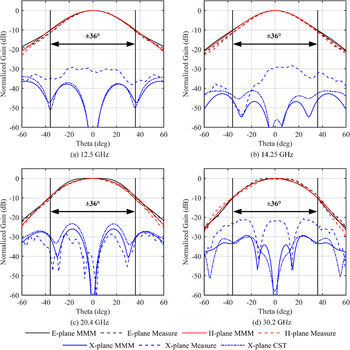
After the demonstration of the full-wave EM simulation, a prototype is then manufactured and measured in our anechoic chamber. Comparison between FEM-based simulation and measurement is carried out with respect to reflection coefficient and port isolation between corresponding standard rectangular waveguide ports, as shown in Fig. 4. The feed model takes into account corresponding feeding devices, which is in accordance with the manufactured prototype. Meanwhile, the radiation patterns at 12.5, 14.25, 20.4, and 30.2 GHz (typical center frequency of each band) by MMM, CST, and measurement, respectively, are compared in Fig. 5. Results by MMM are based on the individual horn in Fig. 2(a), while those by CST and measurement are based on the whole feed antenna in Fig. 2(b).
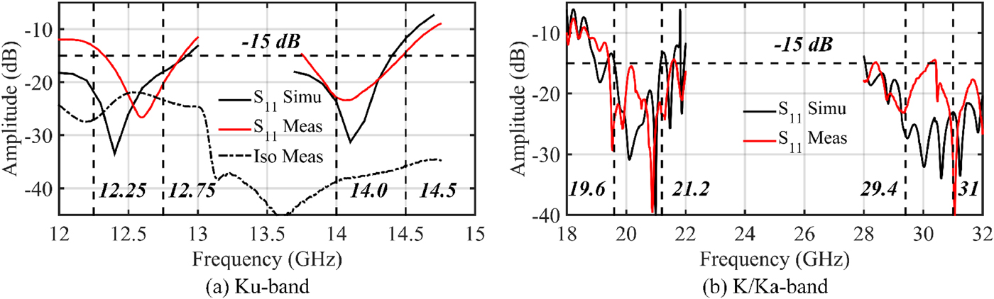
Fig. 4. Comparison between simulation and measurement with respect to reflection coefficient and isolation.

Fig. 5. Radiation pattern comparison between results by simulation and measurement.
The measured reflection coefficient is better than −13.3, −14.3, −15.5, and −14.4 dB in 12.25–12.75, 14.0–14.5, 19.6–21.2, and 29.4–31.0 GHz, respectively. The isolation between the Ku-band OMT ports 1 and 2 is better than 22.0 dB from 12.25 to 12.75 GHz and 35.8 dB from 14 to 14.5 GHz, while the simulated result is always higher than 40 dB. TE10 mode at port 3/4 is set to have the same polarization as port 1. The isolation between port 3 and ports 1/2 is better than 24.9 dB in K band compared with the simulated result of 33.3 dB, while that between port 4 and ports 1/2 is better than 33.3 dB in Ka band compared with the simulated result of 27.6 dB.
Measured E and H planes co-polarization radiation patterns coincide excellently with those by MMM within ±90° at all the frequencies of concern. A constant taper level is achieved at the illumination angle of 36° in all principal planes, which is around −10 dB. Slight differences arise referring to cross-polarization patterns in the 45° planes between simulation and measurement. Results by MMM and CST are, however, in great agreement, which demonstrates the polarization purity of the feeding network. The higher level may result from manufacture tolerance of the dielectric rod, the misalignment between the rod and the metal corrugated horn, or measurement errors. The dielectric rod is, particularly, difficult to maintain the same manufacture tolerance as metal components. Tolerance analysis with respect to the dielectric rod only was carried out, and the results show that ±0.2 mm random manufacture error will result in the worst cross-polarization discrimination of 21 dB at 30.2 GHz, approximately 10 dB lower than the optimized one. The maximum cross-polarization levels, which are approximately −30 dB in Ku band, −25 dB in K band, and −20 dB in Ka band here, can still meet the requirements of common practical applications.
Measured gain equals to 13.37, 13.92, 12.49, and 11.67 dB, compared with simulated results of 13.66, 14.23, 13.32, and 13.6 dB at 12.5, 14.25, 20.4, and 30.2 GHz, which correspond to the insertion loss of 0.29, 0.31, 0.83, and 1.93 dB, respectively. Dielectric loss and conductive loss from the thin nickel layer between the rod and the silver plating layer result in the high loss in Ka band, which could be improved further by redesigning the feeding network for a shorter dielectric-loaded waveguide.
IV. CONCLUSION
A coaxial-type Ku-/Ka-band feed antenna is proposed in this paper. For high operational efficiency in reflector antennas over all bands, the feed takes advantage of the constant phase center and beamwidth. MMM is utilized for multi-band performance optimization, which is of highly computational efficiency compared with commercial full-wave tools. Radiation pattern prediction by spherical wave expansion takes into account the interaction between the feed interior and outer configuration, which results in a complete antenna diagram. The final design promises low cross-polarization and high return loss over all bands, and high isolation between Ku and K/Ka bands. Comparison between our method, CST Microwave Studio, and experimental results shows great agreement, demonstrating its potential in multi-parametric optimization of coaxial-type dielectric-loaded axially corrugated horns.
ACKNOWLEDGEMENT
This work was supported by National Natural Science Foundation of China (NSFC): under the Grant No. 61671178 and “the Fundamental Research Funds for the Central Universities” (Grant No. HIT. NSRIF. 201619).
 Pengyu Zhang was born in Heilongjiang Province, China in 1987. He received the B.E. degree in Communication Engineering and the M.E. degrees in Electromagnetics and Microwave Technology from the Harbin Institute of Technology, Harbin, China, in 2009 and 2011, respectively. He is now pursuing the Ph.D. degree in the Harbin Institute of Technology, majoring in Information and Communication Engineering. His research interests include satellite communication antenna systems, ultra-wideband antennas, and reflectarrays.
 Jiaran Qi was born in Harbin, China, in 1981. He received the B.E. degree in Communication Engineering and the M.E. degrees in Electromagnetics and Microwave Technology from the Harbin Institute of Technology, Harbin, China, in 2004 and 2006, respectively, and the D.Sc. degree from the Aalto University School of Science and Technology (formerly the Helsinki University of Technology), Espoo, Finland, in 2011. He is currently with the Department of Microwave Engineering, Harbin Institute of Technology. His current research interests include electromagnetic wave interaction with complex media, modeling of complex materials, and design of passive millimeter-wave imaging system.
 Jinghui Qiu was born in Heilongjiang Province, China in 1960. He received the B.S., M.S., and Ph.D. degrees in Electrical Engineering from the Harbin Institute of Technology (HIT), China, in 1982, 1987, and 2008, respectively. He jointed HIT in 1987, and is currently a Professor and the Head of the Department of Microwave Engineering, School of Electronics and Information Engineering. His research interests include the developments of ultra-wideband antenna, pulsed antenna, high-power EM pulse technologies, airborne antenna, passive millimeter wave imaging technologies, and communication technologies for the applications of near-space high-speed aircrafts. He has published more than 200 journal and conference papers. Professor Qiu received a number of awards to recognize his distinguished contributions in promoting academic researches for industrial applications including the Science and Technology Progress Awards from the Department of Space and from Aerospace Industry Corporation of China, respectively.