Introduction
Dielectric resonator antennas (DRAs) are gaining more attention due to their attractive features such as zero conduction losses, high gain, and radiation efficiency [Reference Keyrouz and Caratelli1, Reference Divya, Jagadeesh Babu, Madhu, Anguera, Chandra Satapathy, Bhateja and Sunitha2]. Long et al. in [Reference Long, McAllister and Shen3] addressed that, when a dielectric resonator of low Q-factor (10–10 000) is placed on a metallic ground plane and excited, the radio waves enter into the dielectric material. The resonator allows the radio waves to bounce back and forth between the walls of the resonator, which allows to form standing waves in the resonator. As the resonator walls are partially transparent to radio waves, they are radiated into free space.
Multiple-Input-Multiple-Output (MIMO) DRAs are drawing much more attention due to the improved data rate and channel capacity in wireless communication systems [Reference Babu and Krishna4]. The main problem observed in the MIMO system is mutual coupling. When the antennas are compact, the problem of mutual coupling arises, which alters the radiation pattern and degrades the efficiency. Reduction of mutual coupling plays a vital role in the MIMO system. This research article focuses on isolation enhancement in a multi-band MIMO DRA for wireless applications in S, C, and X-bands.
Literature survey discloses the number of conventional techniques [Reference Selvaraju, Jamaluddin, Kamarudin, Nasir and Dahri5–Reference Mukesh Kumar, Binod Kumar and Kumar11] to reduce the effect of mutual coupling. Complementary split-ring resonator (CSRR), floating parasitic elements, electromagnetic band gap structures, neutralization lines, metamaterials, decoupling networks, and defected ground structures (DGS) are used to mitigate the mutual coupling effect. CSRR that acts as an LC tank circuit, when placed between the antenna elements in a MIMO system, blocks the ground surface currents and enhances the isolation.
In this contemporary wireless era, researchers are mainly focusing on multi-band antennas [Reference Chetal, Nayak and Panigrahi12], as a single aerial can be used for a number of applications. The two techniques to achieve multi-band characteristics are hybrid DRA and generation of orthogonal modes. In the proposed design, multi-band characteristics are achieved with hybrid DRA [Reference Gangwar, Sharma, Gupta and Chaudhary13], where a hybrid DRA is the combination of both DRA and microstrip antenna.
The proposed design is termed as hybrid DRA due to the fact that it contains a taper microstrip line with rhombic ring feed, which acts as a microstrip patch antenna and is used along with DRA. The MIMO structure is investigated with and without DRA for multi-band applications. After achieving multi-band characteristics, for enhancing the isolation levels, the structure is investigated with and without defected ground. By incorporating DGS in the partial ground plane, maximum isolation enhancement of 18 dB is achieved. The proposed hybrid DRA resonates at four frequency bands 2.5, 5.09, 6.8, and 9.0 GHz with isolation levels of 22, 34.22, 30.55, and 18.55 dB. The simulations are performed in CST MWS software and the measurements are carried out using vector network analyzer MS2037C.
Antenna design
The proposed MIMO hybrid DRA is developed in three different stages. The first stage comes with the design of feed. The second stage corresponds to feed along with DGS without dielectric loading. The third stage is the proposed design, which involves a DRA-loaded tapered microstrip line feed with a rhombic ring structure and defected partial ground. The design and development of the three configurations are shown in Fig. 1.
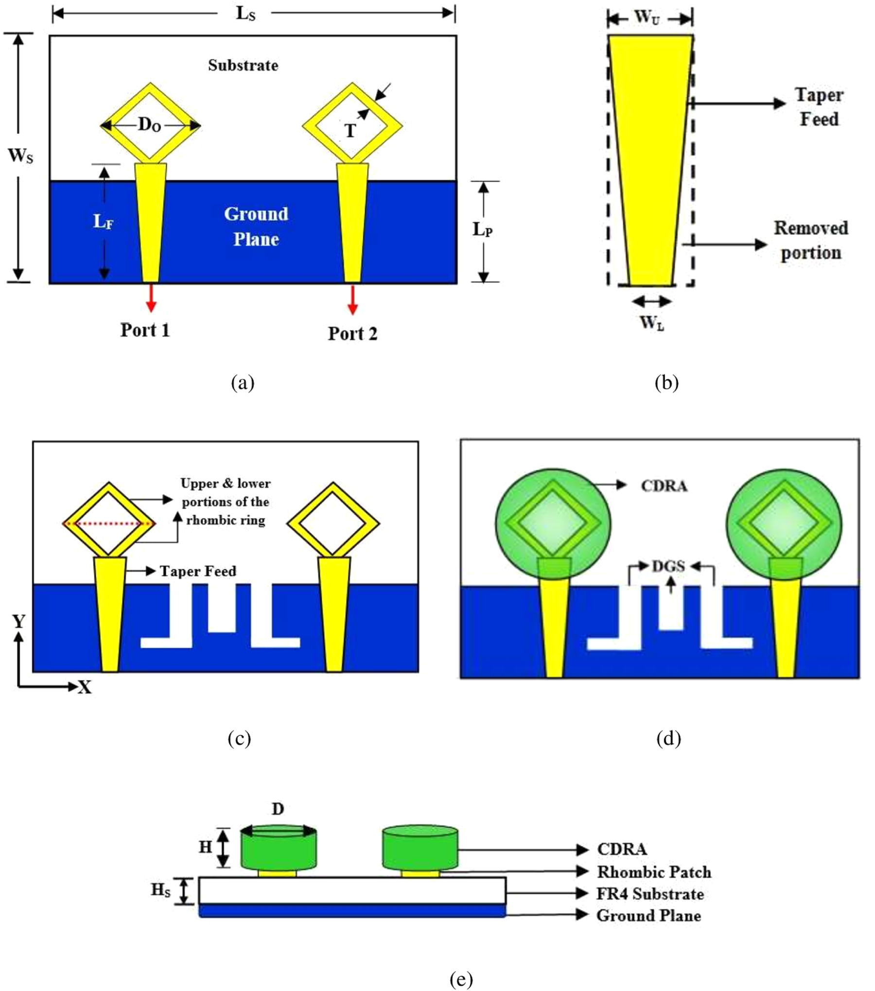
Fig. 1. Evolution of proposed design. (a) Rhombic ring tapered feed along with the partial ground plane, (b) tapered feed mechanism, (c) feed design with DGS in the partial ground, (d) proposed design, (e) side view of the design.
Figure 1(a) shows the taper feed mechanism with a rhombic ring and partial ground plane. Partial ground plane [Reference Lee14] is employed in the design to suppress the back lobe radiation and reduce the mutual coupling in MIMO. Figure 1(b) illustrates the construction of a taper feed. The idea of using taper feed is to provide good impedance matching. The slope of the taper feed [Reference Ramya and Rama Rao15] is calculated by taking the ratio of the width of the wider end to the narrower end of the taper W U/W L. Figure 1(c) exhibits a partial ground plane with DGS and without DRA. To improve the performance of the MIMO system, the partial ground plane is modified. DGS are usually preferred to reduce the mutual coupling in MIMO systems. In the proposed design “L” shaped slots are placed back-to-back with a center slot, which plays a key role in the isolation enhancement. Figure 1(d) shows the proposed hybrid 2 element MIMO DRA, which contains a tapered feed mechanism along with a rhombic ring structure. This overall feed design is used to excite DRA, which resonates at four frequency bands. Figure 1(e) shows the side view of the design.
The construction of the MIMO system is as follows. The cylindrical DRA is placed on FR4 substrate with ɛr = 4.3 and tan δ = 0.025. The dielectric resonator is a ceramic material, which is made up of Alumina (Al2O3) with ɛr = 9.9 and tan δ = 0.0001. Tapered rhombic ring feed excites the cylindrical dielectric resonator antenna (CDRA), which is placed beneath the antenna. The two radiators are placed at a distance of 0.416 λ 0. The hybrid radiator resonates at four frequency bands 2.5, 5.09, 6.8, and 9.0 GHz.
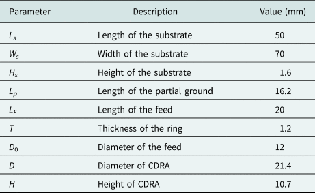
The optimized dimensions of the proposed antenna are listed in Table 1.
Table 1. Optimized dimensions

Antenna analysis and results
The analysis of the proposed hybrid radiator is carried out in two ways.
A. Parametric analysis of feed
B. Parametric analysis of DGS
Parametric analysis of feed
The proposed hybrid antenna resonates at four bands based on the feeding structure along with dielectric loading. The parametric analysis of the reflection coefficient curves for different feed configurations without and with DRA is shown in Fig. 2. Different resonant frequencies are emerged by changing the feed design. The first (violet color) and second (green color) reflection coefficient curves are with the full rhombic ring tapered feed and half rhombic ring tapered feed structures, respectively, without DRA. The third (blue color) and fourth (red color) reflection coefficient curves are with half rhombic ring and full rhombic ring tapered feed structures, respectively, with DRA.

Fig. 2. Reflection coefficient versus frequency.
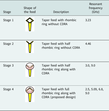
Resonant frequencies excited for four different feed configurations without and with DRAs are shown in Table 2. The first stage shows a tapered microstrip line along with the rhombic ring. This is a feed structure, which acts as a microstrip antenna and the lower resonant frequency 3.23 GHz is excited. In the second stage, the taper microstrip line along with the lower part of the rhombic ring feed without DRA is shown. Here another resonant frequency 4.46 GHz is originated. The other two resonant frequencies 3.0 and 9.0 GHz are excited when DRA is placed above the taper feed with the half rhombic ring as shown in stage 3. Finally, the proposed hybrid MIMO DRA resonates at four frequency bands 2.5, 5.09, 6.8, and 9.0 GHz as shown in stage 4. The %bandwidth achieved at the four frequency bands are 14.6, 10.7, 4.2, and 5.3%, respectively. In stage 4, a slight shift in the first two resonant frequencies is observed. TM11 and TE01δ modes are generated at the first two resonant frequencies in stages 1 and 2, respectively. In stage 3 when DRA is loaded on the half rhombic ring structure (lower part of the rhombic ring), another HE21δ-like mode is excited. According to reference [Reference Guha, Gajera and Kumar16], HE21δ mode is the main source of cross-polarization. Sharma and Gangwar in [Reference Sharma and Gangwar17] mentioned that the cross-pol level is suppressed with another “U” shaped printed line in the annual ring. Here in the proposed design, cross-polarization levels are suppressed by adding the upper part of the rhombic ring, which becomes a full rhombic structure. This full rhombic ring structure along with CDRA not only suppresses the cross-polarization levels but also excites another radiating mode HE12δ.
Table 2. Feed analysis

The resonant modes excited with the proposed design are explained as follows. The configuration of the feed structure is responsible for generating the lower resonant frequency fr 1 = 2.5 GHz. The surface current distribution of the feed is shown in Fig. 3. From [Reference Das, Sharma and Gangwar18], it is evident that the TM11 mode is generated at 2.5 GHz due to two half variations of surface current and the resonant frequency of fundamental TM11 mode for the annular ring is calculated from [Reference Das, Sharma and Gangwar19]. For the proposed tapered rhombic ring feed, the empirical formula to calculate the resonant frequency of TM11 mode is given by


where v represents the velocity of light, r 0is the radius of the rhombic ring, ɛr,sub is the permittivity of the substrate, ɛrs,eff is the effective permittivity of the substrate.
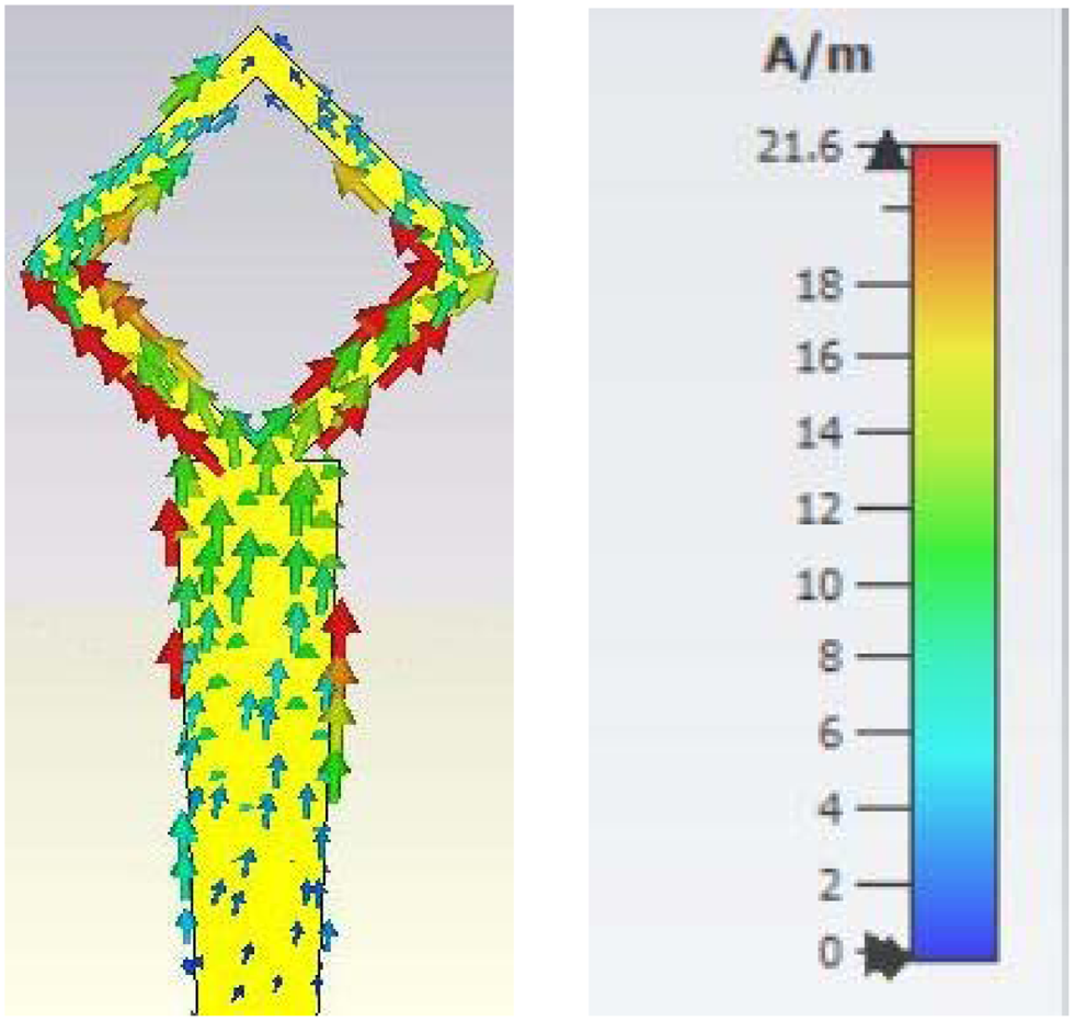
Fig. 3. Surface current distribution of the feed at 2.5 GHz.
The electric field distributions of other resonating modes are shown in Figs 4(a)–4(c). Due to dielectric loading of the tapered feed, another three resonant frequencies are originated. At 5.09 GHz, feed acts like a vertically placed magnetic dipole [Reference Mongia and Bhartia20] and TE01δ mode is generated. The mathematical formula to calculate TE01δ mode in DRA [Reference Gupta, Sharma, Das and Gangwar21] is given by

where,


where d = D/2 represents the radius of CDRA. H eff and ɛdr,effare the effective height and effective permittivity of the proposed radiator.
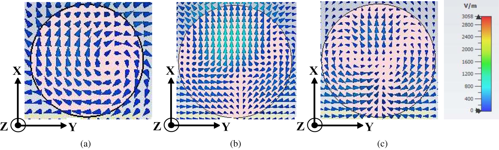
Fig. 4. Electric field distribution in CDRA: top view at 5.09, 6.8, and 9.0 GHz, respectively.
HE21δ-like and HE12δ modes are generated at 6.8 and 9.0 GHz, respectively. At these two frequencies, feed behaves like a magnetic quadrupole and electric dipole, respectively, oriented along the transverse direction. There is no comprehensive formula to calculate the resonant frequency of HE21δ-like and HE12δ available in the literature. But in [Reference Kajfez, Glisson and James22], it is given that the ratio of the resonant frequency of HE12δ to HE11δ is 1.14. The empirical relation to calculate HE11δ mode in CDRA is given by

Parametric analysis of DGS
DGS is one of the simplest and efficient techniques to improve the isolation in MIMO systems. DGS is a defect intentionally placed on the ground plane. It acts as a band pass filter. It alters the direction of the surface currents on the ground plane. Due to DGS, the currents flowing from antenna 1 to antenna 2 decreases, thus enhancing the isolation. The shape and size of the DGS slot control both the fundamental resonant frequency and higher order resonances.
The optimization of DGS is shown in Fig. 5. With a view to reduce the mutual coupling, the initial step in the design process is reducing the length of the ground plane, shown in Fig. 5(a). The partial ground plane reduces the back-lobe radiation by suppressing the surface wave, enhances bandwidth, and provides good impedance matching. After optimizing the partial ground plane, a rectangular-shaped slot with dimensions WSL = 4 mm and LSL = 11.2 mm are etched at the center of the partial ground plane, shown in Fig. 5(b) as DGS1. Altering the position of DGS1 from the center creates an impedance mismatch. So, for proper impedance matching, the slot has to be placed at the center of the partial ground. The isolation achieved with the center slot is 21.49 dB. For further enhancement of isolation, dual L-shaped slots with dimensions WSSL = 3 mm, LSSL = 13.2 mm, WS = 1 mm, and LS = 6 mm are cut from the ground plane on either side of the center slot. The two L-shaped slots are placed in the partial ground, facing and opposing each other, respectively, as DGS2 and DGS3, illustrated in Figs 5(c) and 5(d). After consenting with the dimensions of the feed structure and DGS, a parametric analysis is performed to optimize the dimensions of DGS to get better isolation.
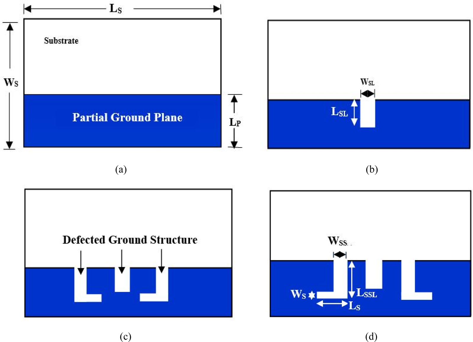
Fig. 5. Optimization of defected ground structure: (a) partial ground plane without DGS, (b) DGS1, (c) DGS2, (d) DGS3.
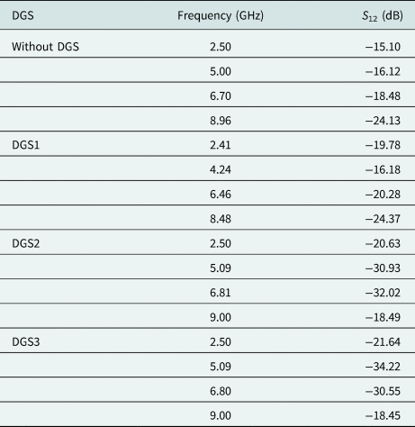
A rigorous parametric analysis is performed to optimize the dimensions of the ground plane, DGS slot positions and dimensions. As seen in Fig. 6, change in the length of the ground plane shifts the resonant frequencies and affects the reflection coefficient as well. Change in the width of L-slot Ws in DGS not only shifts the resonant frequency but also lowers the isolation level. The parametric analysis graph of the transmission coefficient is shown in Fig. 7. It illustrates the improvement in the isolation levels without DGS and with DGS1, DGS2, and DGS3 at the four resonant frequencies. Isolation improvement in the four frequency bands without and with DGS is shown in Table 3.
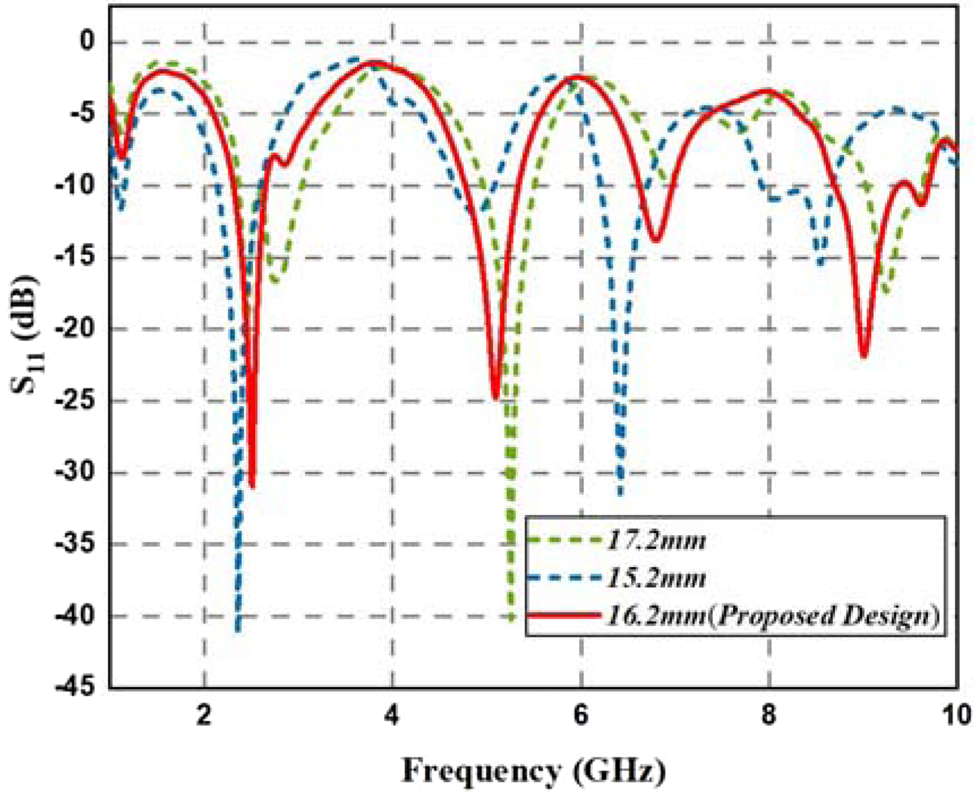
Fig. 6. Parametric analysis of partial ground.
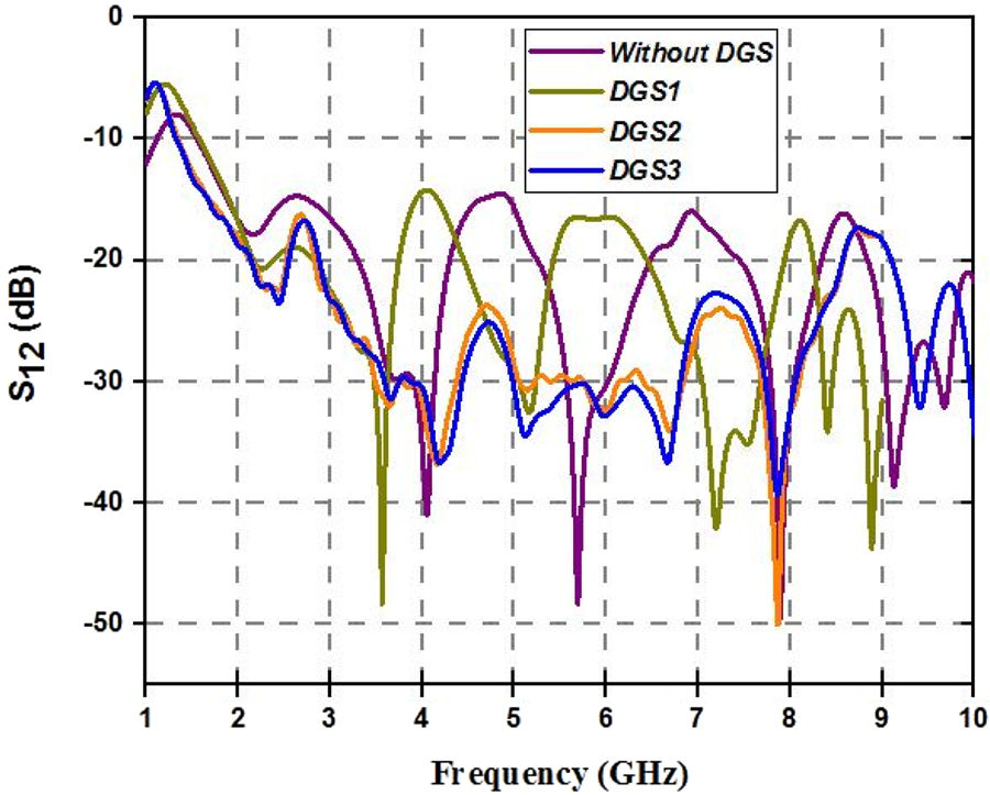
Fig. 7. Transmission coefficient of MIMO antenna.
Table 3. Isolation analysis due to DGS
The surface current distribution at 2.5 GHz with DGS is shown in Fig. 8. It is observed that on both sides of the center slot and L-shaped slots in the ground plane, surface currents flow in opposite directions along the length of the slot and get cancelled at the edges. Due to this, the currents flowing in the ground plane take a longer path to travel from antenna 1 to antenna 2, thus enhancing the isolation.

Fig. 8. Surface current distribution at 2.5 GHz.
The prototype of the fabricated antenna is shown in Fig. 9.

Fig. 9. Fabricated proposed antenna structure: (a) top view, (b) bottom view, (c) feed design.
The simulated and measured scattering parameters of the proposed MIMO DRA are shown in Fig. 10. In the measured results, the resonant frequencies are slightly shifted due to the fabrication tolerances at the feed point.
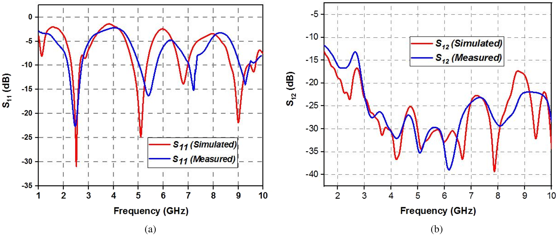
Fig. 10. Scattering parameters: (a) reflection coefficient, (b) transmission coefficient.
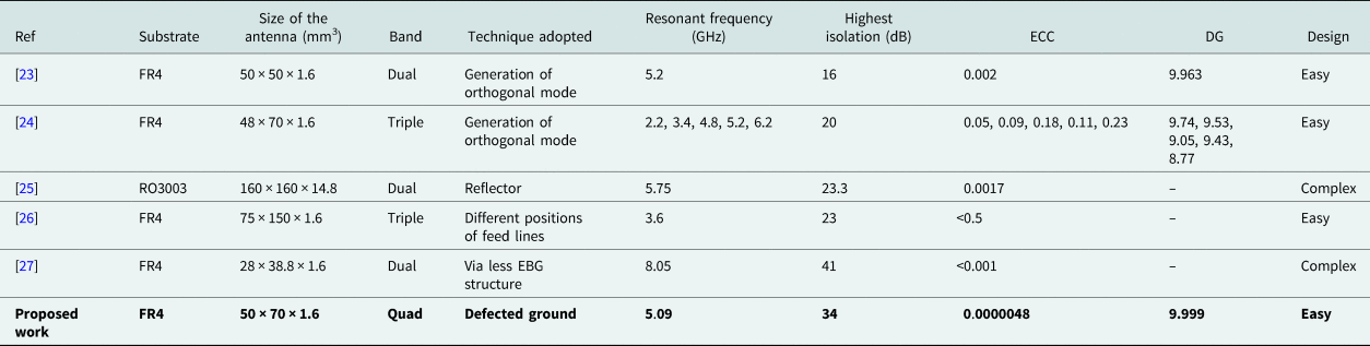
The comparison of the proposed MIMO antenna with other multi-band antennas in terms of isolation is detailed in Table 4.
Table 4. Comparison of the proposed MIMO work with other multi-band MIMO systems

The simulated and measured Co-Pol and X-Pol radiation patterns of E-plane and H-plane of the proposed hybrid MIMO antenna are shown in Fig. 11. The cross-pol level is below 20 dB compared to the Co-Pol at all the four resonant frequencies.
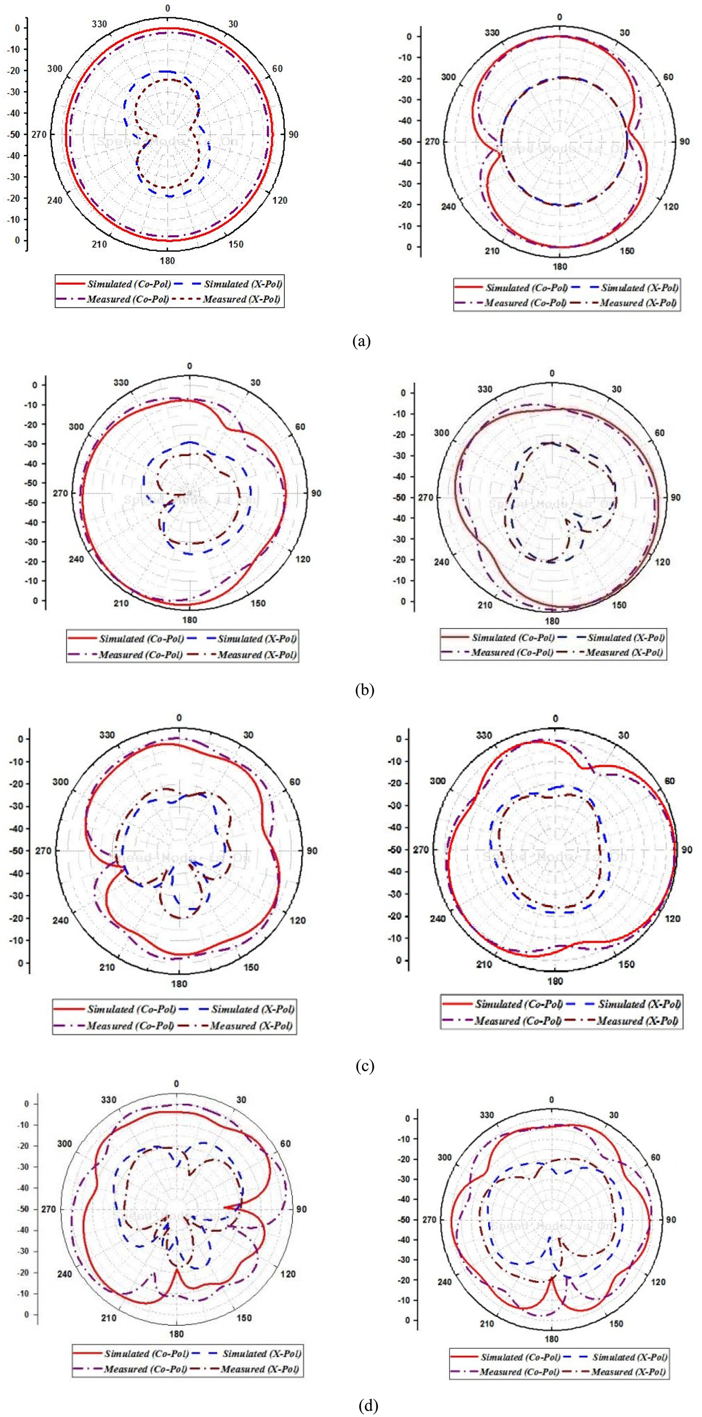
Fig. 11. E-plane and H-plane Co-Pol and X-Pol radiation patterns at (a) 2.5 GHz, (b) 5.09 GHz, (c) 6.8 GHz, and (d) 9.0 GHz.
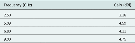
The gain of the proposed MIMO antenna is shown in Fig. 12. At the four resonant frequencies, the respective gain values are shown in Table 5.
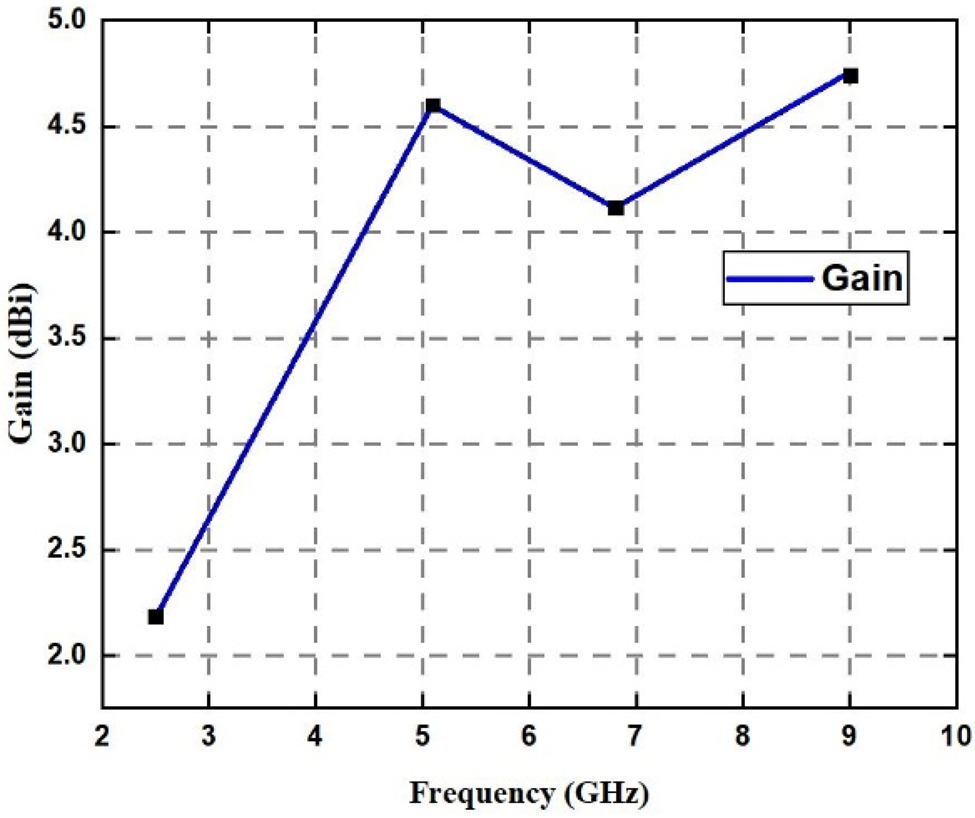
Fig. 12. Gain versus frequency plot.
Table 5. Gain versus frequency

The diversity performances of the MIMO system are evolved from envelope correlation coefficient (ECC) and diversity gain (DG) [Reference Mohammad Saadh, Ashwath, Ramaswamy, Ali and Anguera28].
ECC is a parameter used to find how much the adjacent signals are correlated to each other. In terms of S-parameters, ECC (ρ e) is given in equation 9. The practical value of ECC should be <0.5 for a good radiator. For the proposed antenna, simulated and measured ECC is <0.05, shown in Fig. 13. The measured values of ECC are calculated by substituting the S-parameters in equation 9.

where S 11 is the reflection coefficient and S 12 is the isolation.

Fig. 13. Envelope correlation coefficient (ECC).
DG is another diversity parameter that shows us an increase in the signal-to-noise ratio of a MIMO system. In terms of ECC, DG is given by the formula

For a MIMO system, a DG of 10 is acceptable. The simulated and measured DG performance curve is shown in Fig. 14.
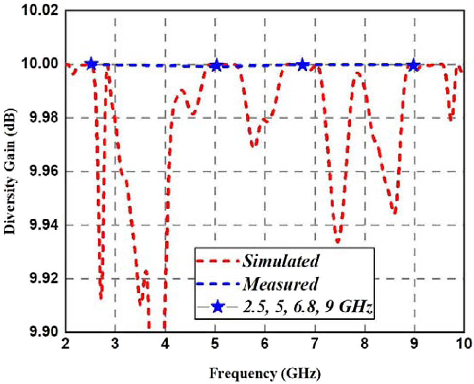
Fig. 14. Diversity gain.
Conclusion
A quad-band MIMO CDRA for RF communication applications is presented in this paper. The proposed radiator resonates at 2.5, 5.09, 6.8, and 9.0 GHz covering applications in S, C, and X-bands. Different radiation modes are excited at different frequencies. DGS technique is employed in this paper to improve the isolation. A high isolation of 34.22 dB is achieved and is more than 18.45 dB in the entire frequency band. Agreeable results are obtained with the diversity performance metrics ECC and DG.
 G. Divya is a Research Scholar, pursuing Ph.D. in the field of Antennas from Jawaharlal Nehru Technological University, Kakinada, Andhra Pradesh, India. She has been working as an Assistant Professor in the Department of Electronics and Communication Engineering at Bapatla Women's Engineering College, Bapatla, Andhra Pradesh, India. She received the B.Tech. (ECE) degree from Jawaharlal Nehru Technological University, Hyderabad and the M.Tech. (Communication Systems) degree from Andhra University. She has published over 15 technical publications in reputed international journals and conferences. She received the best paper award at the IEEE International Conference in 2018. She is a student member of IEEE, one of the largest technical professional organization. Her research areas include microstrip antennas and dielectric resonator antennas for MIMO systems.
 K. Jagadeesh Babu was born in Chirala, Andhra Pradesh, India in 1978. He received the B.Tech. degree from SVH College of Engineering, Machilipatnam in the year 1999, and the M.Tech. and Ph.D. degrees from Jawaharlal Nehru Technological University, Hyderabad, India in 2006 and 2013, respectively. Presently, he is working as a Professor and Head of the Department at St. Ann's College of Engineering & Technology, Chirala, India. Also, he is a Postdoctoral researcher under the Certificate of Excellence in Research program from the Indian Institute of Technology Kharagpur, India. He received Travel Grant from SERB, Department of Science and Technology (DST), India to attend International Conference PIERS-2017 in Singapore. He received the Best Researcher Award from JNTUK University in the year 2018. He is a senior member of IEEE and a life member of IE and ISTE, India. He published nearly 50 research papers in various reputed journals and conferences. His research areas include printed antennas, dielectric resonator antennas, meta-materials, ground-penetrating radar and characteristic mode analysis.
 R. Madhu was born in Warangal district, India in 1980. He received the B.E degree in Electronics and Communication Engineering from Osmania University, Hyderabad, India, in 2003 and the M.Tech degree in Communication Systems from Jawaharlal Nehru Technological University, Hyderabad, India, in 2009 and the Ph.D. degree in Electronics and Communication Engineering from Andhra University, Visakhapatnam, India, in 2014. He is presently working as an Assistant Professor in the Department of Electronics and Communication Engineering, University College of Engineering Kakinada (A), JNTUK Kakinada, India. He has 10 years of teaching experience. He has published more than 40 research papers in various reputed national and international journals and conferences. His research interests include mobile and cellular communications, satellite communications, and GNSS. He is a member of IEEE.