


Introduction
Electron jets (Chen et al., Reference Chen, Park, Hong, Kim, Zhang and Nam2002; Hu et al., Reference Hu, Lei, Wang, Wang, Huang, Wang, Xu, Liu, Yu, Shen, Li and Xu2010), which are collimated outflows from plasma, have potential applications as a compact source of high-energy-density relativistic electrons (Yu et al., Reference Yu, Yu, Shao, Luan, Zou, Ge, Zhang, Wang, Wang, Li, Liu, Ouyang and Wong2015). The electron flows have been widely studied based on the conventional accelerator and laser-driven plasma acceleration (Katsouleas and Dawson, Reference Katsouleas and Dawson1983; Nakajima et al., Reference Nakajima, Fisher, Kawakubo, Nakanishi, Ogata, Kato, Kitagawa, Kodama, Mima, Shiraga, Suzuki, Yamakawa, Zhang, Sakawa, Shoji, Nishida, Yugami, Downer and Tajima1995, Reference Nakajima, Kim, Jeong and Nam2015; Sprangle et al., Reference Sprangle, Esarey and Krall1996; Wagner et al., Reference Wagner, Chen, Maksimchuk and Umstadter1997; Yu et al., Reference Yu, Bychenkov, Sentoku, Yu, Sheng and Mima2000; Salamin and Keitel, Reference Salamin and Keitel2002), especially in direct laser acceleration (Gahn et al., Reference Gahn, Tsakiris, Pukhov, Meyer-ter-Vehn, Pretzler, Thirolf, Habs and Witte1999; Shaw et al., Reference Shaw, Tsung, Vafaei-Najafabadi, Marsh, Lemos, Mori and Joshi2014, Reference Shaw, Lemos, Amorim, Vafaei-Najafabadi, Marsh, Tsung, Mori and Joshi2017), and laser-driven wakefield acceleration (Ting et al., Reference Ting, Moore, Krushelnick, Manka, Esarey, Sprangle, Hubbard, Burris, Fischer and Baine1997; Nakajima et al., Reference Nakajima, Deng, Zhang, Shen, Liu, Li, Xu, Ostermayr, Petrovics, Klier, Iqbal, Ruhl and Tajima2011; Zhang et al., Reference Zhang, Shen, Ji, Wang, Xu, Yu, Yi, Wang, Hafz and Kulagin2012; Albert et al., Reference Albert, Thomas, Mangles, Banerjee, Corde, Flacco, Litos, Neely, Vieira, Najmudin, Bingham, Joshi and Katsouleas2014; Salehi et al., Reference Salehi, Goers, Hine, Feder, Kuk, Miao, Woodbury, Kim and Milchberg2017; Woodbury et al., Reference Woodbury, Feder, Shumakova, Gollner, Miao, Schwartz, Baltuška, Pugzlys and Milchberg2018) schemes. In the conventional accelerator, which is usually of a large scale due to the limited acceleration gradient, charged particles are injected into the electric field and gain energy directly from this acceleration field. In laser-driven plasma acceleration, which can be a relatively compact system, both accelerated charged particles and quasi-neutral plasma flows (Kang et al., Reference Kang, Lin, Shen, Liu, Lei, Fan, Zhou and Wang2016) can be obtained from plasma driven by the high-frequency electromagnetic field. Here, instead of the laser as the driver, we propose a very different method of obtaining the collimated axial electron jets from the cylindrical plasma in the presence of inward radial electrostatic field and axial magnetostatic field. According to the well-known cross-field plasma rotating effect (Wilcox, Reference Wilcox1959; Baker et al., Reference Baker, Hammel and Ribe1961; Fahleson, Reference Fahleson1961; Lehnert, Reference Lehnert1971), the motion of the non-relativistic charged particles can be described as a superposition of three simple motions: a uniform rectilinear drift velocity (Baker et al., Reference Baker, Hammel and Ribe1961) given by  $\! \mathop{E}\limits^{\rightharpoonup} \times \! \mathop{B}\limits^{\rightharpoonup} /B^2$ leading to the rotation of the plasma, a cyclotron motion about an axis parallel to the magnetic field, and a uniform rectilinear velocity in the direction of the magnetic field. Among the three kinds of velocities, only the first is determined by the fields while the others are closely related to the instantaneous fields, which is produced by the interaction of the applied electromagnetostatic field with plasma. Under the applied electromagnetostatic field, the electrons move spirally toward the center of the cylindrical plasma in the transverse plane. Considering the high density of the electrons in the center, the electrons are expected to eject out from the plasma. Here we should note that the jets could be found under the Z-pinch effect (Haines, Reference Haines2011; Zhai et al., Reference Zhai, Li, Bellan and Li2014), resulting from the radial Lorentz force, which originates from the intense current in the axial direction. While jets are generated in both Z-pinches and our cases, the mechanism is different. The experiments of rotating plasma (Wilcox, Reference Wilcox1959; Baker et al., Reference Baker, Hammel and Ribe1961; Fahleson, Reference Fahleson1961; Lehnert, Reference Lehnert1971) have been carried out in the laboratory. With similar structure of axial magnetic field and radial electric field as that in our proposal, the phenomenon of electron rotating is both observed. With the electric field and magnetic field in 108 V/m and 10 T scale, respectively, which are far higher than that in the previous experiments where the jets have not been observed, we found electron jets from our performed particle-in-cell (PIC) simulations and gave the qualitative explanation of the jet formation. With similar setup in the rotating plasma device (Fahleson, Reference Fahleson1961), our proposed model could be achieved in the laboratory when the applied electric field is matched. In our scheme, the coaxial disc-annulus electrode is set along the axis of the cylindrical plasma to produce a radial electrostatic field, which would accelerate the electrons into the center and induce the electron jets. Meanwhile, the axial magnetostatic field is set to collimate the electrons (Bridle, Reference Bridle1986; Zhai et al., Reference Zhai, Li, Bellan and Li2014; Wang et al., Reference Wang, Pei, Han, Wei, Yuan, Liang, Zhao, Zhong, Zhang, Zhu, Li, Li, Li, Zeng, Zou and Zhang2016). The plasma is set as cold state initially, to avoid the effect of the initial temperature of the plasma on the electron jet formation, since the initial temperature of the plasma is conducive to the electron jet formation. (With the plasma of a temperature T = 1 keV at time t = 0 ps, the electron jets with better collimation and higher intensity shown in online Supplementary Figure S1d–1f are achieved than that with the plasma in the cold state at t = 0 ps, shown in online Supplementary Figure S1a–1c, respectively.) The collimated plasma jet could be formed on the plasma focus device (Kasperczuk et al., Reference Kasperczuk, Paduch, Tomasszewski, Zielinskka, Miklaszewski and Szymaszek2016, Reference Kasperczuk, Paduch, Tomaszewski, Miklaszewski, Jach, Swierczynski, Szymaszek, Zielinska and Szymaszek2017), where the conical geometry contributes to the jet formation. Considering the simplification configuration of the system, the plasma in our simulations is cylindrical. (The cubic configuration is also simulated and the electron jets have also been observed.) The absorbed boundary conditions for both fields and particles are set in the simulation. Under the absorbed boundary conditions, the fields transmit totally through the boundary, and the particles are omitted when they contact the boundary material. As is well known, axial magnetic fields exist in celestial bodies, and radial electric fields will be formed owing to the rapid expansions or contractions of the celestial bodies. As the structure of these electric and magnetic fields may be similar to that in our proposed model, the jets observed in celestial bodies may be somewhat related to our model.
In this paper, the validity of the model is confirmed through full three-dimensional PIC simulations in the millimeter scale based on VORPAL (Nieter and Cary, Reference Nieter and Cary2004). Under the application of proper electrostatic and magnetostatic field parameters, electrons eject out from the plasma to form collimated jets, which are perpendicular to the applied electrostatic field. Compared with the jets formed without the application of a magnetostatic field, the jets in the present model is better collimated, as the applied magnetostatic field contributes considerably to the jet collimation. The electric field is found to play a vital role in the jet formation process, according to the distinct distributions of the transverse and longitudinal energy gains of all electrons. Moreover, the ejecting velocity of the jets is close to the speed of light, when the applied electrostatic field reaches 3 × 10¹⁰ V/m.
Simulations and discussions
PIC simulation
In our model, the x direction is noted as the longitudinal direction whereas the yz plane is in the transverse direction. The anode, which is on the axis of the cylindrical cold plasma, has infinite length and uniform charge distribution. According to Gauss’ law, the radial electric field E r is obtained as below
 $$E_{\rm r} = \left\{ {\matrix{ {{{E_{\max} \times r} / {r_0}}} & {r \le r_0} \cr {{{E_{\max} \times r_0} / r}} & {r_0 \lt r \le R_0} \cr}} \right.,$$
where  $r = \sqrt {y^2 + z^2} $. The radii of the anode and plasma are r 0 = 10−2R 0 and R 0 = 3.0 mm, respectively. The cold plasma with the density n 0 = 1.3 × 1014 cm−3 is initially located in the region of
  $-0.5\,{\rm mm} \le x \le 0.5\,{\rm mm,}\,\sqrt {y^2 + z^2} \le R_0$. For simplicity, we assign E max = q l/(2π ε0r 0), in which q l is the amount of charge per unit length and ε0 is the dielectric constant of vacuum. In the simulation, E max = 3 × 10⁸ V/m and the applied longitudinal uniform magnetic field B 0 = 11 T. The simulation box is in the range of −1.0 mm ≤ y, z ≤ 1.0 mm and −3.1 mm ≤ y, z ≤ 3.1 mm, corresponding to a window with 250 × 250 × 250 cells containing five particles per cell. Under the effect of the applied electrostatic and magnetostatic fields, the electron flows eject from both ends of the cylindrical plasma symmetrically and in opposite directions, as illustrated clearly in Figure 1.
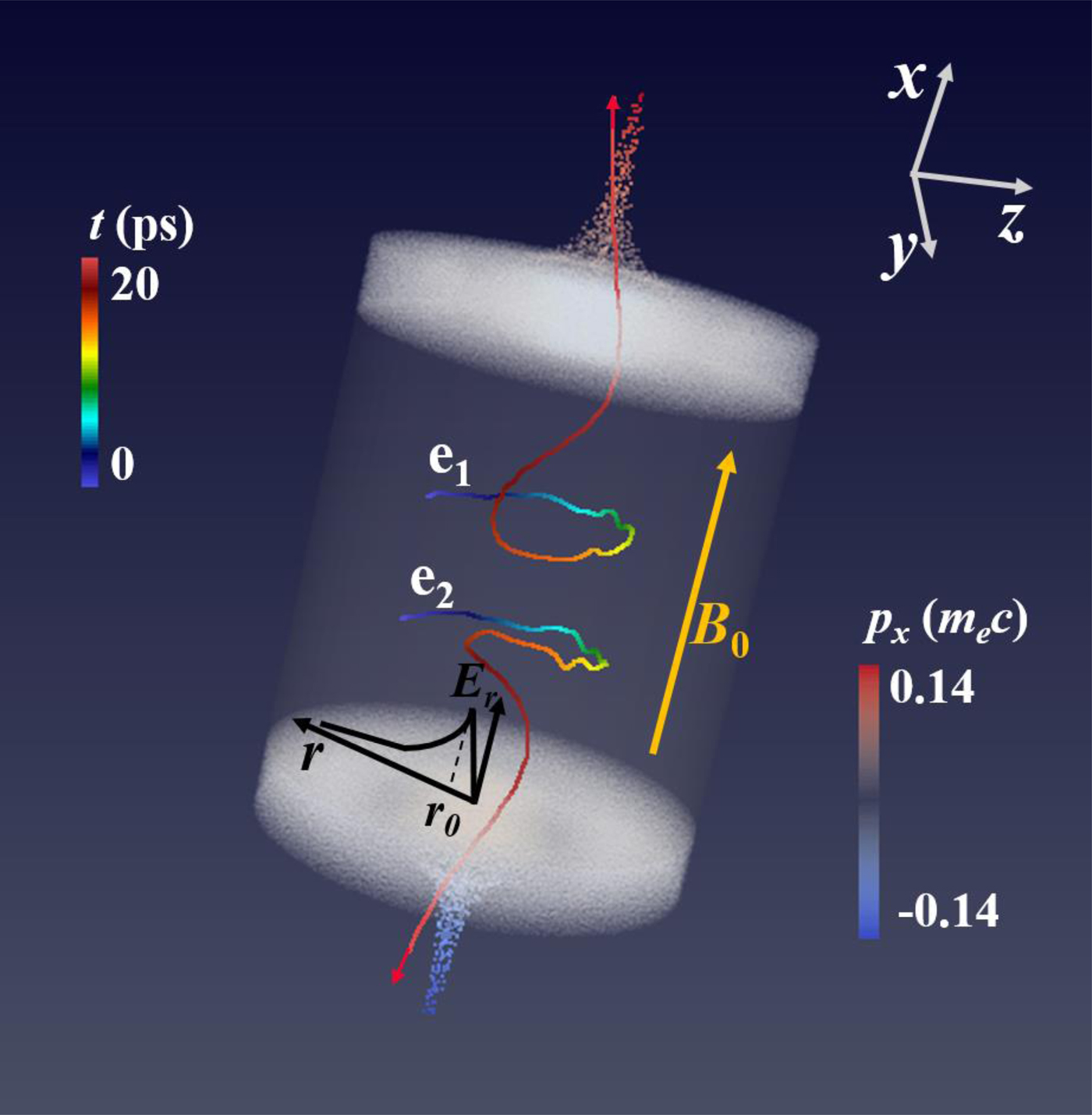
Fig. 1. Simulation results of the jet model. Electron jets are clearly seen at the two ends of the cylindrical plasma, which is shown from the higher longitudinal electron momentum P x at time t = 20 ps, where the origin of the coordinate is at the plasma center. The applied uniform magnetostatic field is B 0 = 11 T in the x direction, and the maximum of the applied radial electrostatic field is E max = 3 × 10⁸ V/m. For a clear demonstration of the tracked localization of electrons, the middle part is left empty to show the tracks of two typical electrons e1 (0.22, −0.19, 0.016 mm) and e2 (−0.17, −0.19, 0.016 mm) from time t = 0 ps to t = 20 ps. The tracks are shown as curved lines colored from blue (cold) to red (warm), respectively.
Illustration of the model results
The simulation results in Figure 1 clearly show that the longitudinal electron momentum P x manifests the formation of the jets. Under the effect of the applied electrostatic and magnetostatic fields, the electrons move toward the center of the cylindrical plasma along spiral tracks. Two spiral lines denote the tracks of two typical electrons e1 and e2 ejecting along the +x and −x directions, respectively, as shown in Figure 1. Their color variations from blue to red indicate the time lapse from 0 to 20 ps. During this period, some electrons are ejected out from the plasma in the longitudinal direction with spiral motion in the transverse direction (also shown in Fig. 2a). Here we should note that some other electrons are ejected away from the plasma in the longitudinal direction with little transverse motion because of their initial localization with intense electric field, whereas others remain in the plasma because of their initial localization with weak electric field.

Fig. 2. Transverse velocity vectors of the electrons in the yz plane of r ≥ 0.5 mm (chosen for clear demonstration) at x = 0.25 mm (within the plasma) when t = 2 ps (a) with the applied magnetostatic field and (b) without the applied magnetostatic field.
As shown in Figure 1, the jet is well collimated, when compared with that under the same condition but without the applied magnetostatic field (shown in Fig. S2), which indicates that the applied magnetostatic field is of great significance in the jet collimation process. The motion of the electrons at x = 0.25 mm in the presence of the applied magnetostatic field B 0 = 11 T is displayed in Figure 2a and the equivalent motion when B 0 = 0 T is displayed in Figure 2b. Here only the transverse velocity of the electron is considered. In the case of B 0 = 0 T, the electrons are accelerated directly into the plasma center and later disperse in the transverse direction. The electrons experience very different motion while in the presence of the applied magnetostatic field. They move spirally in the transverse plane as shown clearly in Figure 2a, which leads to the collimation of the jets. Here we note that the direction of the force imposed on the electrons initially is transverse, but eventually they gain longitudinal velocity and some of them eject from the plasma. The induced electric field (IEF) and the induced magnetic field (IMF) play important roles in the electron jet formation, which will be discussed below.
IEF and IMF
At time t = 2 ps, the longitudinal current and IEF are already formed as shown in Figure 3a and 3d, respectively. The IEF E x is formed at x = ±0.5 mm around the center of the yz plane, as shown in Figure 3d; it is conductive to accelerate the electrons to form the currents in Figure 3a. The jets are formed with a small divergence angle and small cross-section later, as shown in Figure 3b and 3c at t = 6 ps and t = 14 ps, respectively. Meanwhile, some return electrons are generated, which induce the additional return current shown in Figure 3c and the additional inverse electric field shown in Figure 3e and 3f, which are not beneficial for the jet formation.

Fig. 3. Distribution of the longitudinal current density (first row) and the longitudinal IEF E x (second row) in the xoy plane at time t = 2 ps in (a), (d), t = 6 ps in (b), (e), and t = 14 ps in (c), (f). The black rectangular box denotes the outline of the plasma in the xoy plane. The third row shows the distribution of transverse IMF in the yz plane at x = 0.25 mm (one-quarter of the longitudinal length of the plasma from x = 0 mm) at time t = 2, 6, 14 ps in (g), (h), and (i), respectively, where the blue-yellow scale in the background shows the strength of the transverse IMF and the superimposed white arrows indicate the transverse IMF vectors.
The IMF is simultaneously formed. Here the transverse IMF at x = 0.25 mm is shown in Figure 3g–3i. In Figure 3h and 3i, the toroidal IMF around the jet implies the collimation of the jet. The rotation direction of the transverse IMF in the outer toroid is opposite to that in the center shown in Figure 3i, which indicates the phenomenon of return current seen in Figure 3c. At the symmetric longitudinal positions of the plasma, the rotation directions of such transverse IMF are opposite and the strengths are almost the same. These characteristics are in accordance with that of the IEF E x. Therefore, the transverse IMF in the middle plane of the plasma is also close to zero.
The evolutions of the IEF and IMF with time have been verified at three different positions of the plasma. Within 2 ps, the IEF reaches high amplitudes, which is clearly illustrated in Figure 4a–4c. Moreover, the induced B x, B y, and B z in Figure 4d–4f have trends similar to those of the induced E x, E y, and E z, respectively, in spite of an approximate phase difference of π. Overall, the IMF and IEF oscillate strongly inside the plasma and weakly outside the plasma. After 2 ps, the amplitude of E x gradually reduces with time. Especially at x = 0.7 mm (outside the plasma) shown in Figure 4a, E x is always negative, which is beneficial for the acceleration of the electrons outside the plasma and the formation of the jets. More interestingly, the periodical oscillation of the IMF appears related to certain waves produced in the plasma, which is worthy of further study.

Fig. 4. Evolutions of (a–c) the IEF normalized to E max = 3 × 10⁸ V/m and (d–f) the IMF normalized to 10−3 B 0 in (a, d) x, (b, e) y, and (c, f) z directions at different locations along the x-axis at x = 0.3 mm (within the plasma), x = 0.5 mm (on the top surface of the plasma), and x = 0.7 mm (outside the plasma).
Explanation of electron jet formation
To check the effects of the IEF and IMF shown in Figure 3 on the jet formation, we focus on the dependence of electron ejection on the electric field. We divide the electric field into two components,  $E_x\hat{x}$ and
  $\! \mathop{E}\limits^{\rightharpoonup} \!\!_{\bot} $ (
 $\! \mathop{E}\limits^{\rightharpoonup}_\!\!\!_{\bot} = E_y\hat{y} + E_z\hat{z}$), where
  $\hat{y}$ and
  $\hat{z}$ denote the unit vectors in the y and z directions, respectively. The equation of electron motion is
  $dp^2/dt = 2eE_xp_x + 2e \! \mathop{E}\limits^{\rightharpoonup}\!\!_{\bot} \times \mathop{p}\limits^{\rightharpoonup}\!\!_{\bot} $, where
  $ \! \mathop{E}\limits^{\rightharpoonup}\!\!_{\bot} \! \times \! \mathop{p}\limits^{\rightharpoonup}\!\!_{\bot} = E_yp_y + E_zp_z$. In addition, the energy of each electron is γ2 = 1 + (p 2/m 2c 2) = 1 + Γx + Γ⊥ (Gahn et al., Reference Gahn, Tsakiris, Pukhov, Meyer-ter-Vehn, Pretzler, Thirolf, Habs and Witte1999). According to the position and momentum of all electrons in the PIC simulation, we calculate
 $${\rm \Gamma} _x = \int_0^t {\displaystyle{{2eE_xp_x} \over {{(mc)}^2}}dt{\rm ^{\prime}},} $$
 $${\rm \Gamma} _\bot = \int_0^t \displaystyle{2e\! \mathop{E}\limits^{\rightharpoonup}\!\!_{\bot} \times \! \mathop{p}\limits^{\rightharpoonup}\!\!_{\bot} \over {{(mc)}^2}} dt^{\prime},$$
where Γx is the longitudinal energy gain owing to the acceleration of the electric component  $E_x\hat{x}$ (the IEF in the longitudinal direction), and Γ⊥ represents the transverse energy gain from
  $\! \mathop{E}\limits^{\rightharpoonup}\!\!_{\bot} $ (including the applied electrostatic field and transverse IEF). As shown in Figure 5a, the energy gain of the electron Γ⊥ is much larger than Γx at t = 0.4 ps when the electrons obtain longitudinal velocity and the jet is not formed clearly, as illustrated in Figure 5b. The electrons with energy gain Γ⊥ larger than Γx constitute 98.31% of the total electrons, which proves that the transverse electric field acceleration is the dominant acceleration mechanism. Under the condition p x = 0 and with no longitudinal force imposed on the electrons at t = 0 ps, it can be seen that the increments of p ⊥ are converted into those of p x through the effect of the transverse IMF (shown in Figure 3g–3i), that is, the
  $\mathop{v}\limits^{ \vskip2pt {\scale75% \rightharpoonup}}\!\!{_{\vskip2pt \bot} \!\times \mathop{B}\limits^{ \vskip2pt {\scale75% \rightharpoonup}}\!\!{_{\vskip2pt \bot} $ interaction. Therefore, the power source of the electrons ejecting from the plasma results from the transverse IMF, and the distribution of E x (shown in Figure 3d–3f) clearly verifies the ejection of the jets in the opposite directions from the two ends of the cylindrical plasma, as shown in Figure 1.

Fig. 5. (a) Distribution of the accelerated electrons in the energy gain space (Γx, Γ⊥) at t = 0.4 ps within the range 1.0 × 10⁻¹⁷ < Γx < 5.0 × 10⁻¹² and 1.0 × 10⁻⁵ < Γ⊥< 3.0 × 10⁻⁵ chosen for distinct display. The color bar represents the number of electrons (N). (b) Distribution of the longitudinal electron momentum P x normalized to m ec within −0.2 mm ≤ y, z ≤ 0.2 mm at t = 0.4 ps, where the dashed lines on the left and right denote the locations of x = −0.5 mm and x = 0.5 mm, respectively.
In order to obtain larger longitudinal electron momentum P x, we study the relationship between P x and the applied electrostatic field shown in Figure 6. The jets can be formed when E max is in a wide range of  $10^4 \, {\sim \!\! 1} 0^{12}\,{\rm V/m}$. As shown in Figure 6, we can find that the higher the applied electrostatic field is, the higher P x is. Especially, when E max approaches 3 × 10¹⁰ V/m, the electron momentum P x could reach 0.5m ec.

Fig. 6. Distribution of the longitudinal electron momentum P x normalized to m ec within −0.074 mm ≤ y, z ≤ 0.074 mm (around the x-axis) at t = 20 ps under different applied electrostatic fields.
Considering that the strong electric and magnetic fields are difficult to be synchronously applied on the time scale of ps, two simulations with 2 ps delay of (1) the applied magnetostatic field and (2) the applied electrostatic field are carried out, respectively. For the former case (2 ps delay of the applied magnetostatic field), the electron jets achieve better collimation and higher intensity shown in Figure 7a–7c, compared with that with the electrostatic and magnetostatic fields applied on the plasma synchronously shown in Figure 3a–3c, respectively. It indicates that the plasma with directed transverse velocity is beneficial for the formation of the electron jets. Compared with another case of 2 ps delay of the electric field (only the applied magnetostatic field interacting with the cold plasma within 2 ps), the magnetostatic field makes no effect on the electron jets in 2 ps. As shown in Figure 7d–7f, the results of the simulation are almost the same as that in the proposed scheme (shown in Figure 3a–3c) except for 2 ps delay. All these results indicate that the applied electrostatic field play a significant role of the jet formation, and the applied magnetostatic field only contributes a lot on the collimation of the jets.

Fig. 7. Distribution of the longitudinal current density in the xoy plane at time t = 2 ps in (a), (d), t = 6 ps in (b), (e), and t = 14 ps in (c), (f). The black rectangular box denotes the outline of the plasma in the xoy plane. In the first row (a)–(c), 2 ps delay of the applied magnetostatic field. In the second row (d)–(f), 2 ps delay of the electrostatic field.
Based on the role of the electric and magnetic fields for the electron jet formation, a 2 ps delay of the applied magnetostatic field is set with the applied electrostatic field E max = 3 × 10⁹ V/m. The longitudinal electron momentum P x could reach 0.7m ec at t = 20 ps as shown in online Supplementary Figure S3a, owing to the time delay of the applied magnetostatic field to great extent. The total charge of the ejected electrons (with energy above 10 keV) Q e reaches 2 × 10¹⁰e at time around t = 8 ps as shown in online Supplementary Figure S3b, and later keeps stable, which may be of great value for the stable and high total charge. The electron jets obtain good collimation at t = 20 ps, shown in online Supplementary Figure S3c, which confirms the stability of the output of the total charge. If the parameters such as the plasma density are optimized, higher charge could be obtained.
In the above analysis, we showed that the collimated jets are formed when proper electric and magnetic fields are applied in the cylindrical plasma. We also notice that in the active galactic nuclei (AGN) jet (Marscher, Reference Marscher2006; Zhai et al., Reference Zhai, Li, Bellan and Li2014), the density is approximately 103 m−3 and the length is in the 1020 m scale. According to the scaling law of the particle motion equations of the system, the voltage and magnetic fields in the celestial bodies should be 1018 V and 10−8–10−9 T, respectively, for similar jets to be formed. These values are reasonable, as the voltage is 1.1 × 10¹⁸ V and the magnetic field is 2 × 10⁻⁹ T in the AGN jet. Owing to this set of parameters being consistent with that of electric and magnetic fields in the celestial bodies, our model may provide theoretical explanations for the jet formation in the celestial bodies (Stehle et al., Reference Stehle, Ciardi, Colombier, Gonzalez, Lanz, Marocchino, Kozlova and Rus2009) to some extent.
Conclusions
In conclusion, the electrons gather into the center of the plasma spirally and collectively under the condition of proper applied electrostatic and magnetostatic fields. Initially, the transverse electric field acceleration is the dominant acceleration mechanism. Meanwhile, the transverse energy of the electrons is converted into the longitudinal energy via the effect of the transverse IMF. The electrons gain longitudinal momentum, thus forming the jets. The longitudinal electron momentum varies considerably under different applied electrostatic fields. Notably, the maximum velocity of electrons is close to the speed of light when the maximum applied radial electrostatic field reaches 3 × 10¹⁰ V/m. Based on the scaling law, the jets observed in the celestial bodies can be explained by our model to some extent, as the electric and magnetic fields in the celestial bodies are similar to the conditions in our model.
Supplementary material
The supplementary material for this article can be found at https://doi.org/10.1017/S0263034618000381.
Acknowledgments
This work is supported by the National Natural Science Foundation of China (Grant No. 11335013, 11374319, 11575274, 11127901, and 11674339), the Ministry of Science and Technology of the People's Republic of China (Grant No. 2016YFA0401102), and the Strategic Priority Research Program of the Chinese Academy of Sciences (Grant No. XDB16).


