


Introduction
The electromagnetic waves carry information including amplitude, phase, direction, frequency, and polarization information. Using polarization information on processing technology to develop polarized radar is an effective approach, which solves four intimidations of military radar facing and improves the capability of radar detection and anti-jamming. Dual-polarized antenna can form a pair of work mode with orthogonal polarization and equal frequency at the same time, and then it can receive all of the polarization information, have a strong capability of anti-jamming, improve system sensitivity and work in some application fields such as passive electronic reconnaissance, passive radar, and wideband communication and detection. The design and realization of dual-polarized antennas have become the focus of research in the field of the antenna. Nowadays, the commonly used dual-polarized antenna elements are dual-polarized dipole antennas, dual-polarized micro-strip patch antennas, dual-polarized waveguide slot antennas, and so on. In the design of dual-polarized antenna element, beam width and the isolation between two polarization ports should be considered, besides working frequency range, bandwidth, return loss, gain, and so on. For example, Yang et al. researched a wideband ±45° dual-polarized directional antenna with high gains. The isolation between two polarization ports was better than 32 dB and gains were higher than 9.2 dBi at the range of 2.5–3.8 GHz [Reference Yang, Jiao, Zhou and Luo1]. Yu et al. researched a new type of antenna element for wideband wide-angle dual-polarized phased array antennas which was composed of Vivaldi antenna, and achieved electrical connection by using metallic posts [Reference Yu, Wu, He and Zhu2]. Ren et al. presented a wideband and high-gain dual-polarized antenna based on split-ring resonators. The purpose of using metamaterials was to improve antenna gain and broaden the bandwidth [Reference Ren, Ding and Guo3]. Wang et al. presented an antenna merging inverted-cone monopole and cross bow-tie dipole to achieve dual polarizations while maintaining a wide bandwidth [Reference Wang, Shen and Zhao4]. Zhu et al. researched a novel dual-polarized patch antenna for ultra-wideband applications which was composed of a square patch and four capacitively coupled feeds to enhance the impedance bandwidth, and the antenna has achieved an impedance bandwidth of 112% [Reference Zhu, Gao, Ho, Abd-Alhameed, See, Brown, Li, Wei and Xu5]. In the literature [Reference Adamiuk, Zwick and Wiesbeck6], the advantages of proposed antenna, which adopted Vivaldi antenna element, were ultra-wideband, low cross-polarization, and small dimensions within working frequency range of 3.1–10.6 GHz. In the literature [Reference Ding, Gao, Wu, Qu, Zhang and Wang7], a dual-band dual-polarized end-fire antenna was proposed, that its ISR structure was loaded to improve the gain in end-fire direction. In the literature [Reference Saxena, Kanaujia, Dwari, Kumar and Tiwari8], a simple compact dual-polarized ultra-wideband MIMO antenna was presented with the circularly polarized band for WiMAX (5.5 GHz) and WLAN (5, 5.2 GHz) applications which adopted feed points of micro-strip slot coupling. In conclusion, the common dual-polarized antenna structures are symmetric and asymmetric structures by using basic antenna. The symmetric structures with two antenna elements implementing dual-polarized antenna are same and orthogonally placed. The asymmetric structures are that the two antenna elements to implement dual-polarized antenna are different, but this way can implement dual polarization. At the same time, the antenna performance can be improved by adding metamaterials in the antenna, using metamaterials structures and so on.
The feature of Vivaldi antenna includes wideband, low cross-polarization, wide wave beam, and end fire. Its main performance is determined by a slot line which is graded according to the exponential curve. Different open widths radiate different electromagnetic signals. Thus, the maximal opening width of the radiation patch is determined by the minimum operating frequency of the Vivaldi antenna, i.e. the maximal slot size of the radiation patch is λ/2 (λ is the wavelength value of the lowest working frequency), and the minimal opening width of the radiation patch is determined by the maximum operating frequency. According to the radiation mechanism of Vivaldi antenna, work mechanism is similar to the TEM mode horn antenna. In other words, the E-plane metal of the horn antenna is equivalent to the cover on the substrate directly, and the waveguide part of the horn antenna is equivalent to the coupling slot line. The energy is transmitted to the matching cavity by electromagnetic coupling, then passes through the coupling slot line to the open slot line, then along the open slot line direction, and finally is radiated at the corresponding resonant slot line according to a different frequency. Vivaldi antenna is a kind of common antenna in wideband antenna field. The research focuses on the following directions: wideband, multi-band frequency, circular polarization, mode of feeding, and dual polarization. For example, in the literature [Reference Sonkki, Sánchez-Escuderos, Hovinen, Salonen and Ferrando-Bataller9], a wideband, dual-polarized Vivaldi antenna or tapered slot antenna with over a decade of bandwidth was presented which was composed of inserting two orthogonal Vivaldi antennas in a cross-shaped form without a galvanic contact. In the literature [Reference Yan, Gogineni, Camps-Raga and Brozena10], an ultra-wideband 2–18 GHz dual-polarized Vivaldi antenna array was presented where the whole of slot line is curved, but this antenna structure was not easy to assemble and an SMP connector was used instead of a typical SMA connector. In the literature [Reference Hung Loui, Weem and Popovic11], an optimized-taper antipodal Vivaldi slot with a bandwidth of 2.5:1 was the dual-polarized antenna element which adopted exponential tapered balun within the operating frequency range of 0.8~4 GHz. In the literature [Reference Yang, Liu and Geng12], a miniaturized ultra-wideband double-layered Vivaldi antenna was proposed, in which optimized slots are inserted in the radiation patches to obtain a low-frequency resonance at the range of 2.5–11 GHz. Wu et al. researched a new wideband circularly polarized antenna array with high gain and low side lobe working in the total X-band; that element was Vivaldi antenna and the method of matching slot line to coaxial line was using Chebyshev impedance convertor [Reference Wu, Wei, Zhao and Li13]. Xu et al. presented a novel cross circular-polarized antenna array in which the element was Vivaldi antenna and the edge of the element adopted a sawtooth structure [Reference Xu, Zhang, Wang, Zhu and Lan14]. Kang et al. researched a dual-polarized orthogonal Vivaldi antenna with high port isolation in which its structure was a novel exponentially tapered slot-edge structure [Reference Kang, Chen and Li15]. Zhang et al. researched an ultra-wideband dual-polarized Vivaldi antenna with low cross-polarization and a choke-slot was added to suppress the surface wave of the antenna to reduce the rear flap of the antenna [Reference Zhang, Wang, Huo, Yang and Wang16]. To sum up, there are three main features as follow: firstly, many Vivaldi antenna elements commonly adopt slot structure or printed dipole structure; secondly, slot line structure is usually linear; finally, antenna structure is simple and easy to assemble. The antenna structure using curved slot line from the literature [Reference Yan, Gogineni, Camps-Raga and Brozena10] was not easy to assemble. One of the technical difficulties of Vivaldi antenna is the design of balun and feed structure. In this paper, a dual-polarized Vivaldi antenna is presented, which is easy to assemble and has an improved new balun. The improved balun consists of two bent coplanar strip lines and a slot line. The improved balun structure avoids the intersection of transmission lines and reduces size.
In this paper, a wideband dual-polarized Vivaldi antenna with improved balun feed is presented, which is suitable to use in some fields. Then the structure of dual-polarized Vivaldi antenna element is designed and simulated through electromagnetic simulation software, CST. After that, the designed dual-polarized Vivaldi antenna is fabricated and measured, and the measured results of impedance characteristics and radiation patterns are provided. Finally, a research conclusion is drawn.
Structure design of the dual-polarized Vivaldi antenna with improved balun feed
In this paper, the structure model of wideband dual-polarized Vivaldi antenna with improved balun feed is presented in Fig. 1. The designed antenna is composed of two Vivaldi antenna elements, which are orthogonally located. The employed dielectric substrate is FR-4 (εr = 4.3), for which the substrate thickness is 1 mm and the metal copper foil thickness is 0.036 mm. In order to achieve dual-polarized operating model, each element is fed by employing the electromagnetic coupling from micro-strip line to slot line. The micro-strip line is located on the other side of the dielectric substrate, and a sector-shaped branch structure at the end of the micro-strip line is adopted to achieve impedance matching. The output part of the micro-strip line is connected to the inner conductor of a coaxial cable. The outer conductor of the coaxial cable is connected with the metal ground plane of Vivaldi antenna to achieve the conversion of the micro-strip line to the coaxial cable. Adopting the theory of electromagnetic coupling, a micro-strip line is converted to the resonant cavity on the side of the dielectric substrate and slot line. The most prominent advantage of the feed structure is that it avoids the intersection of lines and saves lines.
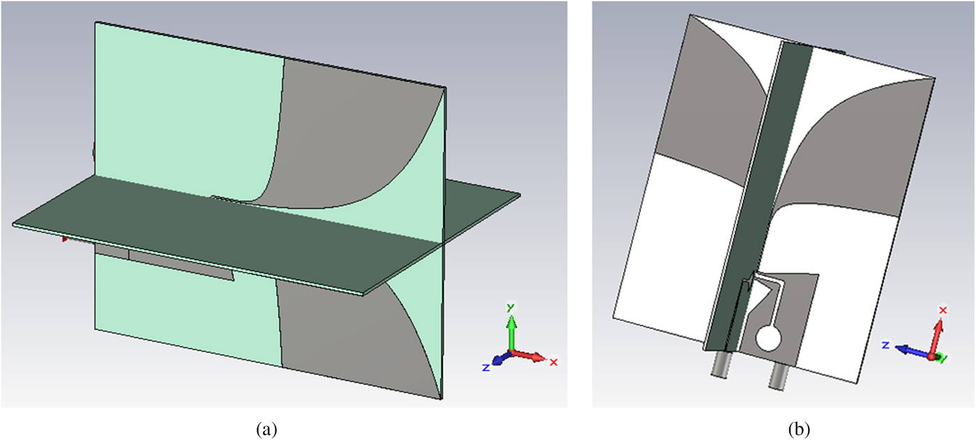
Fig. 1. The perspective of the proposed antenna model.
The exponential printed dipole structure is determined by highest and lowest of working frequency. The exponential tapered curve can be determined by (1) and (2) [Reference Bian, Lv, Jin and Sun17]. p 1(x 1, y 1) and p 2(x 2, y 2) are the beginning and the end points of the exponential tapered curve.
 $$y = C_1e^{\alpha x} + C_2,$$
 $$C_1 = \displaystyle{{y_2 - y_1} \over {e^{\alpha x_2} - e^{\alpha x_1}}},C_2 = \displaystyle{{y_1e^{\alpha x_2} - y_2e^{\alpha x_1}} \over {e^{\alpha x_2} - e^{\alpha x_1}}}.$$
The size of coplanar strip line depends on the calculation formula of micro-strip impedance [Reference Yu, Li, Wu, Wu and Qian18],
 $$Z = \displaystyle{{87} \over {\sqrt {\varepsilon _r + 1.41}}} \ln \left( {\displaystyle{{5.98H} \over {0.8W + T}}} \right),$$
where H is the thickness of the dielectric substrate, W is the width of the coplanar strip line, and T is the thickness of the coplanar strip line. The size of slot line is determined by the calculation formula of slot line impedance [Reference Janaswamy and Schaubert19] when 3.8 ≤ εr ≤ 9.8,  $0.0015 \le w\_sl/\lambda _0 \le 0.075$,
 $$\eqalign{ Z_0 =\,& 73.6 - 2.15\varepsilon _r + \left( {638.9 - 31.37\varepsilon _r} \right)\left( {w\_sl/\lambda _0} \right)^{0.6} \cr & {\rm +} \left( {36.23\sqrt {\varepsilon _r^2 + 41} - 225} \right)\displaystyle{{w\_sl/H} \over {\left( {w\_sl/H + 0.876\varepsilon _r - 2} \right)}} \cr & {\rm +} 0.51\left( {\varepsilon _r + 2.12} \right)\left( {w\_sl/H} \right)\ln \left( {100H/\lambda _0} \right) \cr & {\rm} - {\rm 0}{\rm. 753}\varepsilon _r\left( {H/\lambda _0} \right)/\sqrt {w\_sl/\lambda _0},} $$
where  $w\_sl$ is the width of the slot line. The calculation formulas help to establish a preliminary antenna model, and the final model is decided by simulated results. The size of coplanar strip line and slot line is determined by impedance, and there is no effective method for slot position, which is determined by simulated results.
In this paper, the optimal structure is shown in Fig. 2 and the optimal size is shown in Table 1. The diameter of the inner conductor is 1.27 mm, and the influence of coaxial cable on the antenna performance is as small as possible. In the curvature of exponential taper, α is 0.06 and 0.35. W is 0.5 mm.
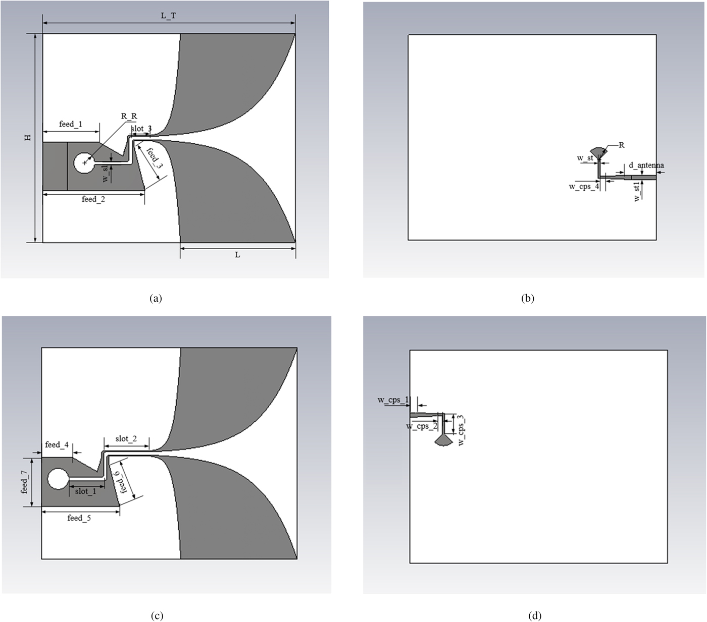
Fig. 2. The engineering drawing of wideband dual-polarized Vivaldi antenna with improved balun, (a) Vivaldi side of engineering drawing of port 1, (b) the feed side of engineering drawing of port 1, (c) Vivaldi side of engineering drawing of port 2, (d) the feed side of engineering drawing of port 2.
Table 1. Parameter table of the presented antenna structure (units: mm)

The electromagnetic simulation of the dual-polarized Vivaldi antenna with improved balun feed
In this paper, the electromagnetic simulation software is used to simulate the radiation performance of the presented antenna. According to the performance requirements, the antenna structure of dual-polarized Vivaldi antenna is designed. The return loss of ports 1 and 2 is shown in Figs 3(a) and 3(b). The return loss of ports 1 and 2 is <−10 dB. The isolation between two polarization ports is shown in Fig. 3(c). The VSWR of port 1 and the VSWR of port 2 are both around 1.5 within the frequency range of 2–3.5 GHz. The isolation between two polarization ports is <−15 dB in the operating frequency band.

Fig. 3. The simulation results of circuit characteristics, (a) the return loss of port 1, (b) the return loss of port 2, (c) the isolation between two polarization ports.
Figs 4 and 5 show the electric energy density of the proposed antenna at 2, 2.5, and 2.7 GHz. According to the electric energy density, both the energy distribution and the current transmission path are clear.

Fig. 4. Simulated electric energy density of port 1, (a) positive structure of electric energy density at 2 GHz, (b) reverse structure of electric energy density at 2 GHz, (c) positive structure of electric energy density at 2.5 GHz, (d) reverse structure of electric energy density at 2.5 GHz, (e) positive structure of electric energy density at 2.7 GHz, (f) reverse structure of electric energy density at 2.7 GHz.
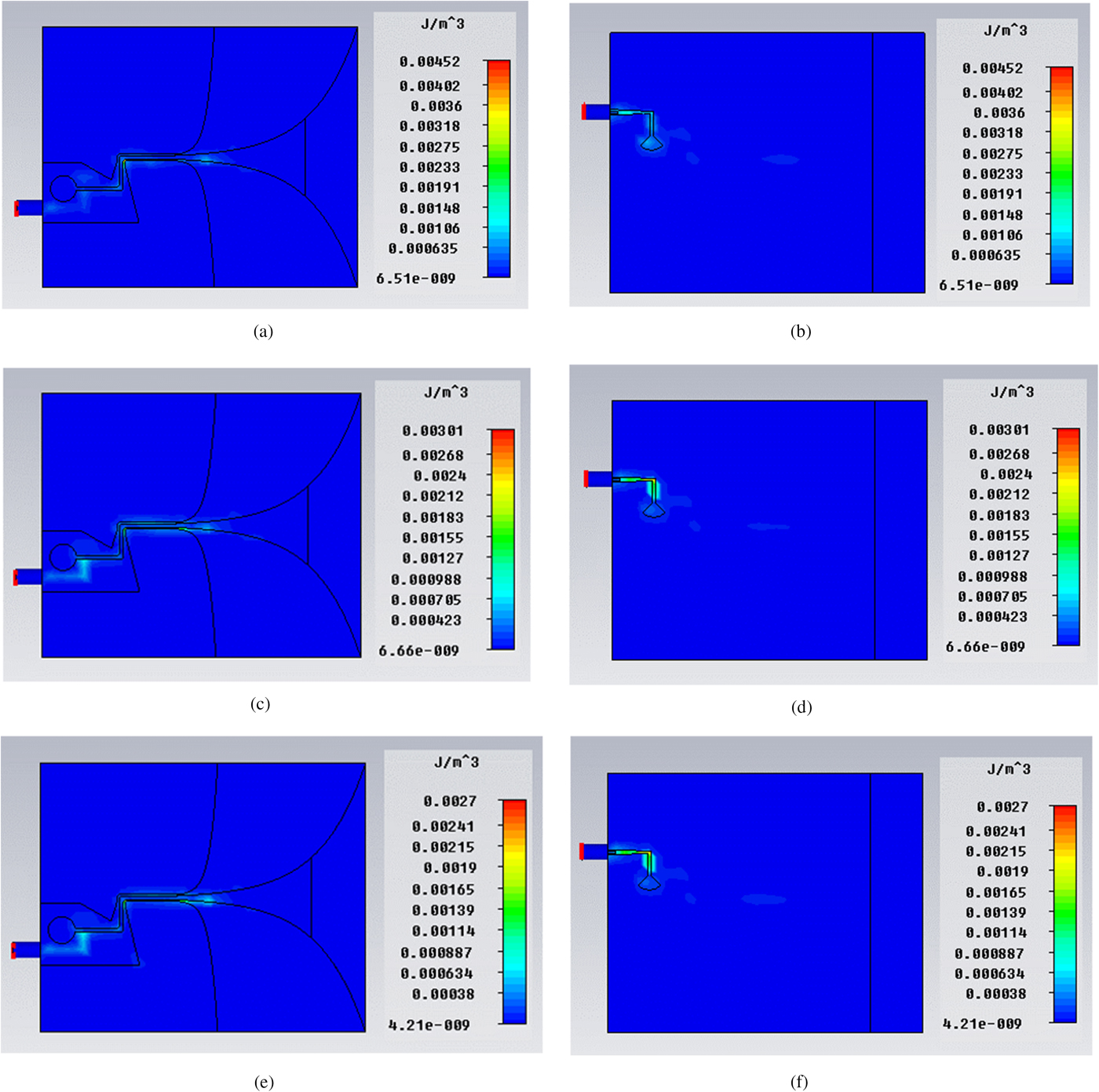
Fig. 5. Simulated electric energy density of port 2, (a) positive structure of electric energy density at 2 GHz, (b) reverse structure of electric energy density at 2 GHz, (c) positive structure of electric, energy density at 2.5 GHz, (d) reverse structure of electric energy density at 2.5 GHz, (e) positive structure of electric energy density at 2.7 GHz, (f) reverse structure of electric energy density at 2.7 GHz.
The antenna radiation direction is along the x-axis. Then the overall structure of the antenna is rotated so that the maximum radiation direction is along the z-axis. The simulation radiation patterns of dual-polarized Vivaldi antenna at 2, 2.5, and 2.7 GHz are presented in Figs 6, 7, and 8, respectively. At each frequency point, the radiation patterns of the two polarization ports at the xoz and yoz planes are provided, respectively. According to the simulated radiation patterns, it can be observed that the designed antenna has wide radiation, regular pattern shape, and low back lobe. The beam shape is more regular, and the radiation gain of the two polarized ports is basically equal, and both of them are >2 dB.
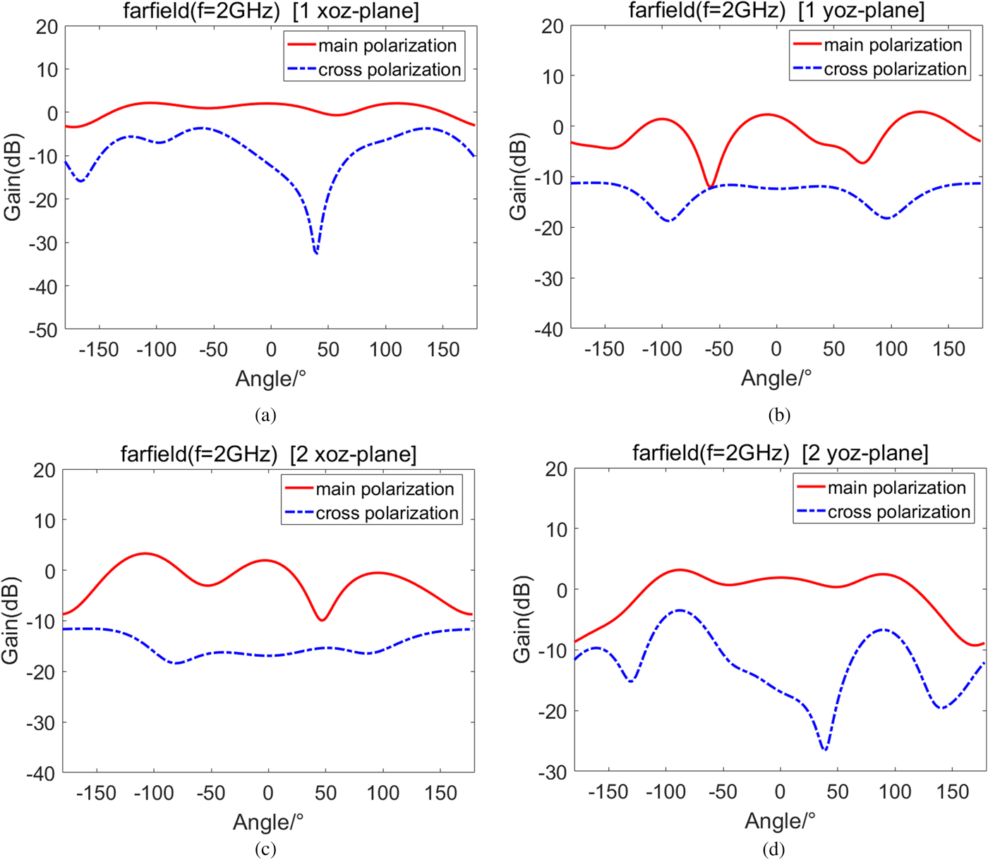
Fig. 6. The radiation pattern at 2 GHz, (a) the pattern of port 1 at xoz plane, (b) the pattern of port 1 at yoz plane, (c) the pattern of port 2 at xoz plane, (d) the pattern of port 2 at yoz plane.
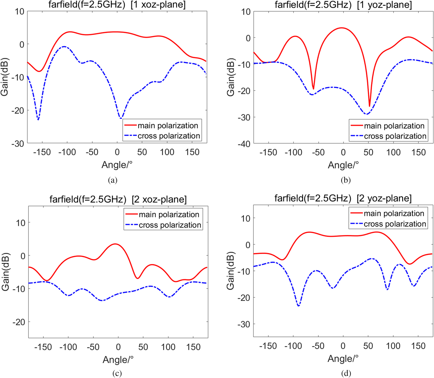
Fig. 7. The radiation pattern at 2.5 GHz, (a) the pattern of port 1 at xoz plane, (b) the pattern of port 1 at xoz plane, (c) the pattern of port 2 at xoz plane, (d) the pattern of port 2 at yoz plane.
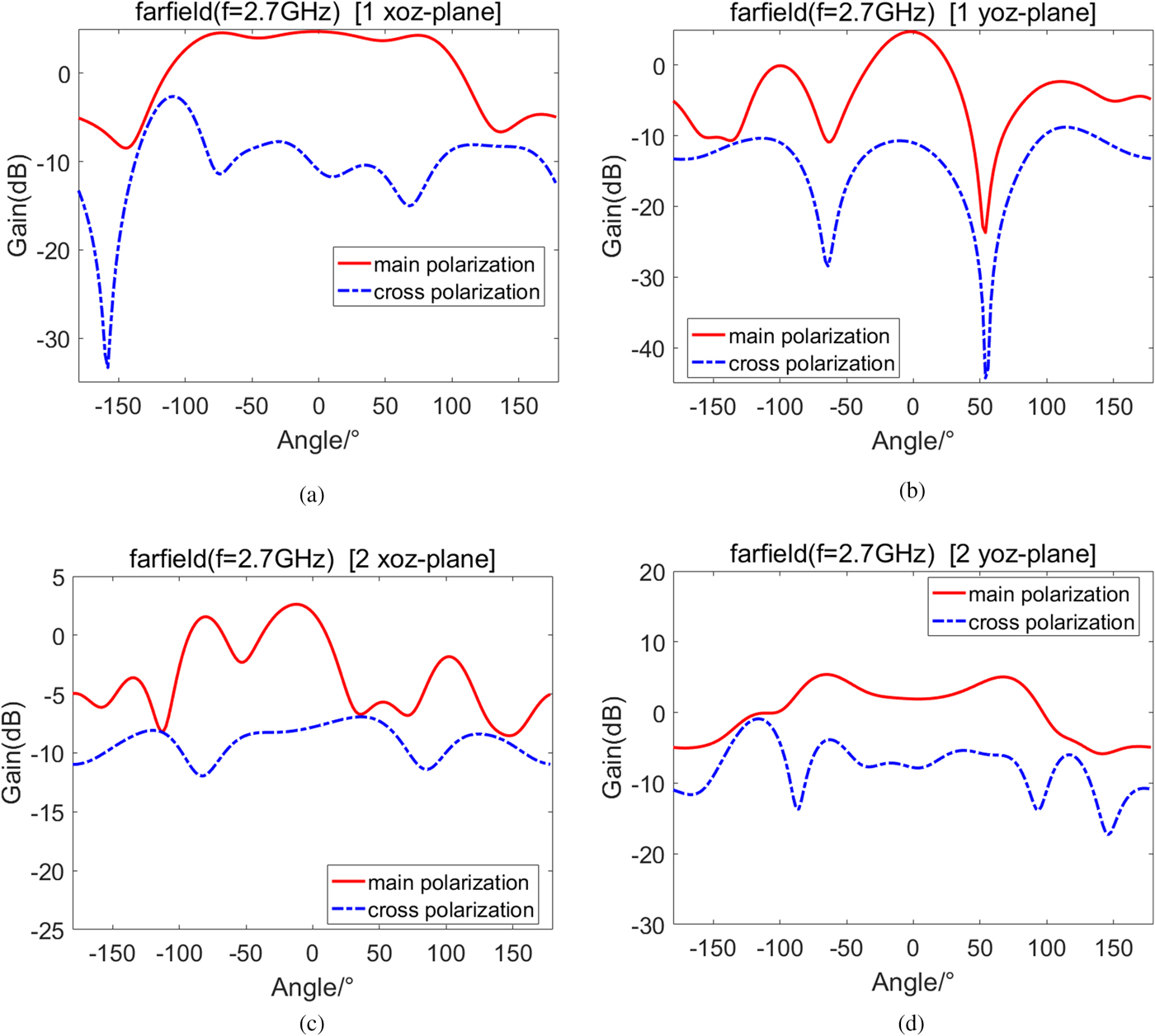
Fig. 8. The radiation pattern at 2.5 GHz, (a) the pattern of port 1 at xoz plane, (b) the pattern of port 1 at yoz plane, (c) the pattern of port 2 at xoz plane, (d) the pattern of port 2 at yoz plane.
The simulation accuracy mainly depends on the discretization of the structure. The accuracy can be improved by the encryption grid, and truncation error in transient simulation is a source of error. The curve of S parameter procedures ripples waves due to truncation error. The influence of simulation accuracy on circuit characteristics of the proposed antenna is shown in Fig. 9. According to the comparison diagram of simulated results of S parameter, no matter the accuracy is one-thousandth, one ten-thousandth or one hundred-thousandth, the simulated results of S 11 and S 21 are basically consistent. When accuracy is one-thousandth, the simulated result of S 22 is not more precise than other accuracy, but the simulated results is accurate and reliable.
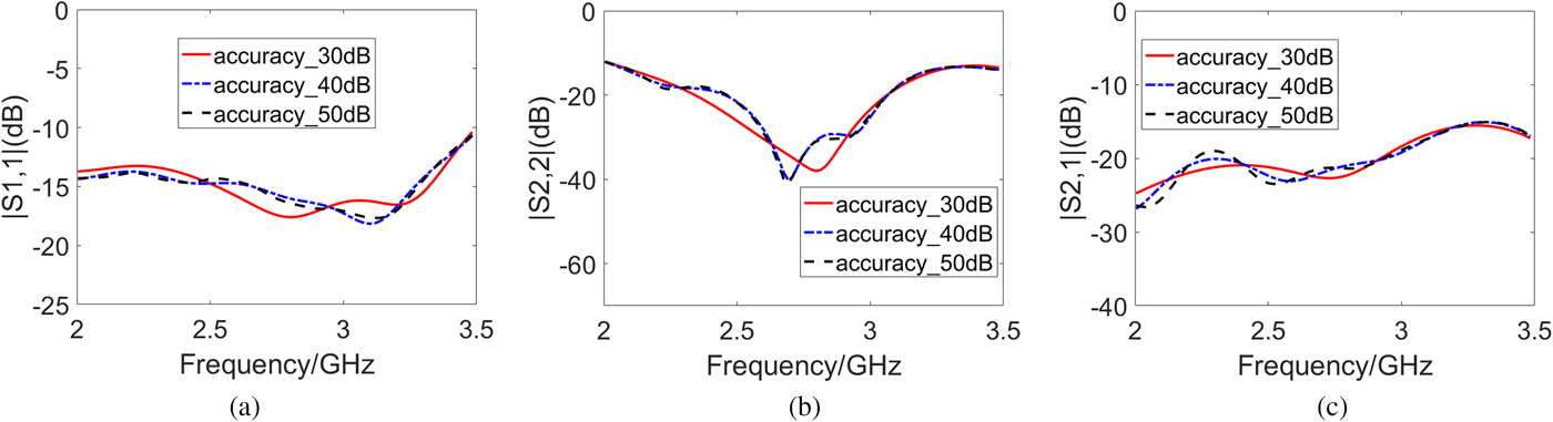
Fig. 9. The influence of simulation accuracy on circuit characteristics proposed antenna, (a) the influence of simulation accuracy on S 11, (b) the influence of simulation accuracy on S 22, (c) the influence of simulation accuracy on S 21.
In this section, the influence of several key parameters on the performance of the antenna circuit is discussed such as the diameter of the fan-shaped matching branch, R_R. Figure 10 presents the influence of parameter R_R on the performance of the antenna circuit. In the range of 2–2.262 GHz, with the increasing of R_R, the return loss of port 1 becomes worse, and in the range of 2.62–3.5 GHz, the return loss of port 1 becomes better. In the range of 2–3.5 GHz, with the increasing of R_R, the return loss of port 2 becomes better. R_R has little effect on the isolation between two polarization ports. Thus, the optimal result of R_R is 5 mm.
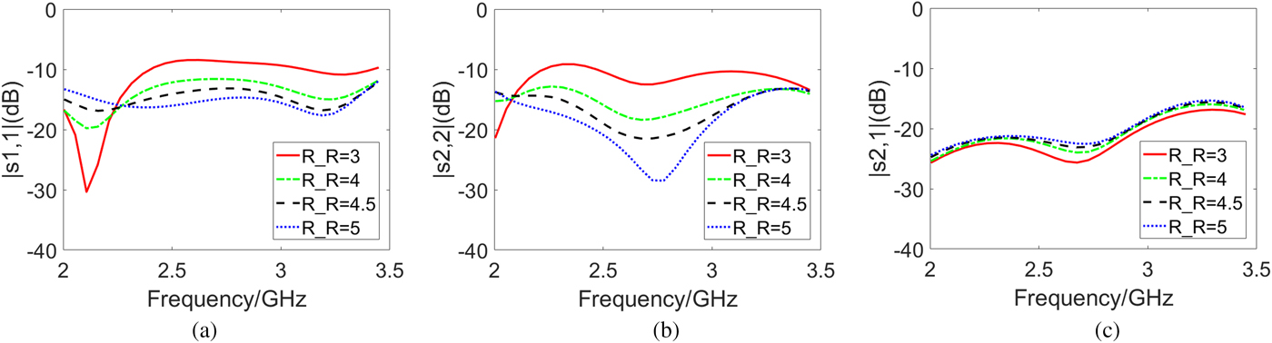
Fig. 10. The influence of parameter R_R on circuit characteristics proposed antenna, (a) the influence of R_R on return loss of port 1, (b) the influence of R_R on return loss of port 2, (c) the influence of R_R on isolation.
The influence of parameter w_st on the antenna circuit performance is shown in Fig. 11. As the w_st varies from 0.5 to 1.5 mm, the resonance frequency moves toward the low-frequency part. w_st has little effect on isolation between two polarization ports, too.
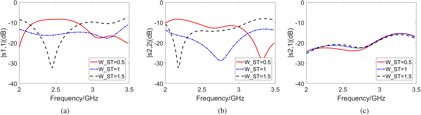
Fig. 11. The influence of parameter w_st on circuit characteristics proposed antenna, (a) the influence of w_st on return loss of port 1, (b) the influence of w_st on return loss of port 2, (c) the influence of w_st on isolation.
Fabrication and test of dual-polarized Vivaldi antenna with improved balun feed
According to the designed antenna structure and size, the dual-polarized Vivaldi antenna has been fabricated and its prototype photo is shown in Fig. 12.
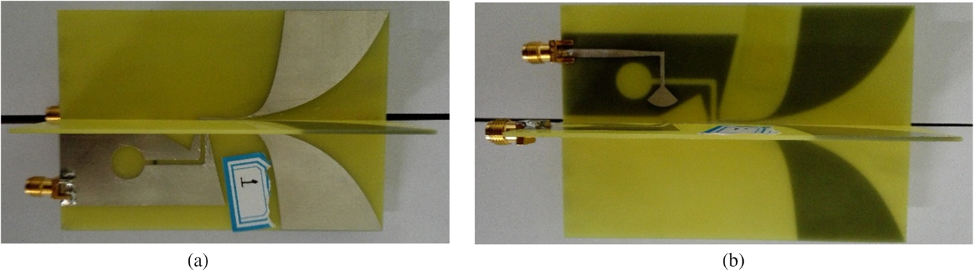
Fig. 12. The prototype photo of dual-polarized Vivaldi antenna with improved balun feed.
The measured results of input circuit characteristics of fabricated dual-polarized Vivaldi antenna are shown in Fig. 13. The measured results are measured in the microwave dark room meeting design requirements. The measured results have certain differences from the simulation results. The return loss of measured results is basically <−10 dB at the operation frequency range and the polarization port isolation is <−25 dB. The measured result of isolation degree is better than simulated results. The measured result of S 22 is basically better than the simulated result, especially at high frequencies. The measured result of S 11 at high frequencies is basically better than the simulated result, but the measured result of S 11 at low frequencies is worse than the simulated result. Generally, the measured result of return loss and VSWR are better than the simulated results due to the loss of transmission line. That is because material error and processing error cause the difference and the resonance is undesirable.
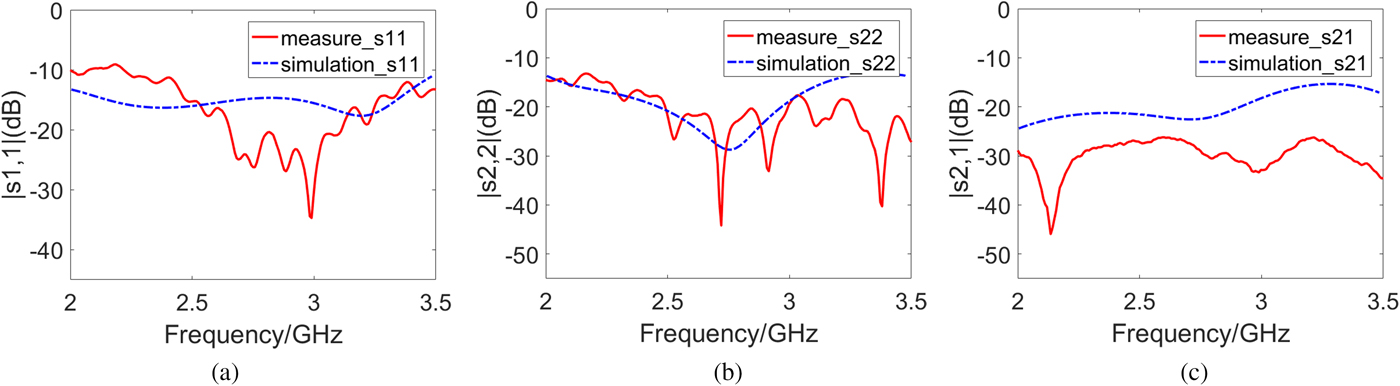
Fig. 13. The circuit characteristics of fabricated dual-polarized Vivaldi antenna, (a) the return loss of port 1, (b) the return loss of port 2, (c) the isolation between two polarization ports.
The measured results of radiation patterns at 2, 2.5, and 2.7 GHz for the dual-polarized Vivaldi antenna are presented in Figs 14, 15, and 16, respectively. In order to compare with the radiation pattern of simulated results, the processed antenna is rotated to make the direction of radiation along z-axis. Each graph gives the radiation pattern of two ports at the xoz and yoz planes, respectively. As shown in the figures, the main polarization of tested results is similar to the simulated results, and the cross-polarization of tested results is basically better than the simulated results. But the beam width of simulated results is larger than the tested results. That is because material error and processing error cause the difference and the resonance is undesirable.
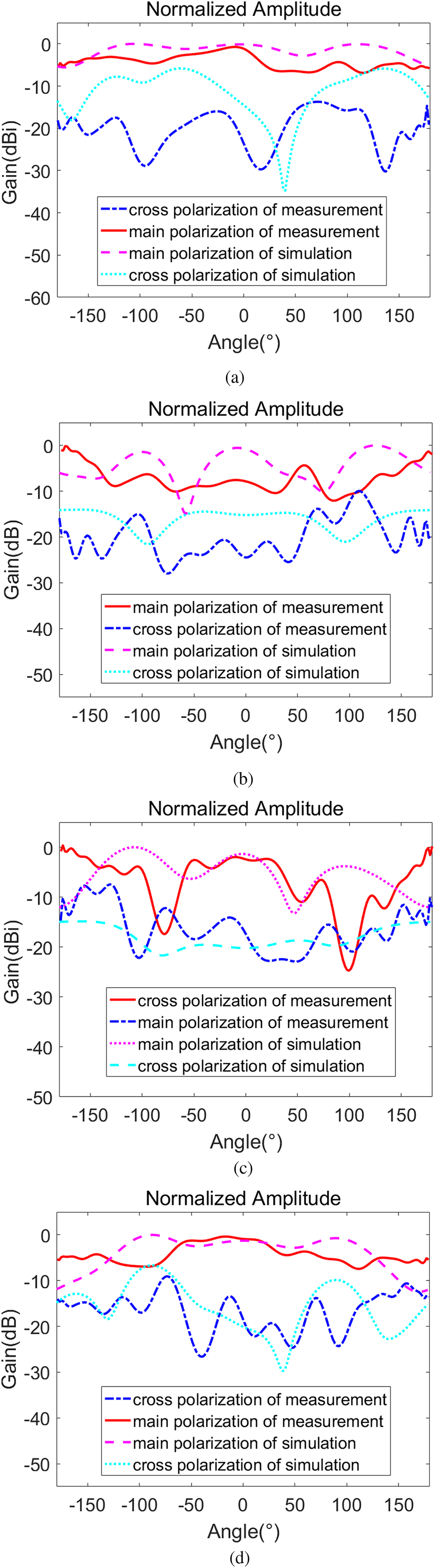
Fig. 14. The radiation pattern at 2 GHz, (a) the pattern of port 1 at xoz plane, (b) the pattern of port 1 at yoz plane, (c) the pattern of port 2 at xoz plane, (d) the pattern of port 2 at yoz plane.

Fig. 15. The radiation pattern at 2.5 GHz, (a) the pattern of port 1 at xoz plane, (b) the pattern of port 1 at yoz plane, (c) the pattern of port 2 at xoz plane, (d) the pattern of port 2 at yoz plane.
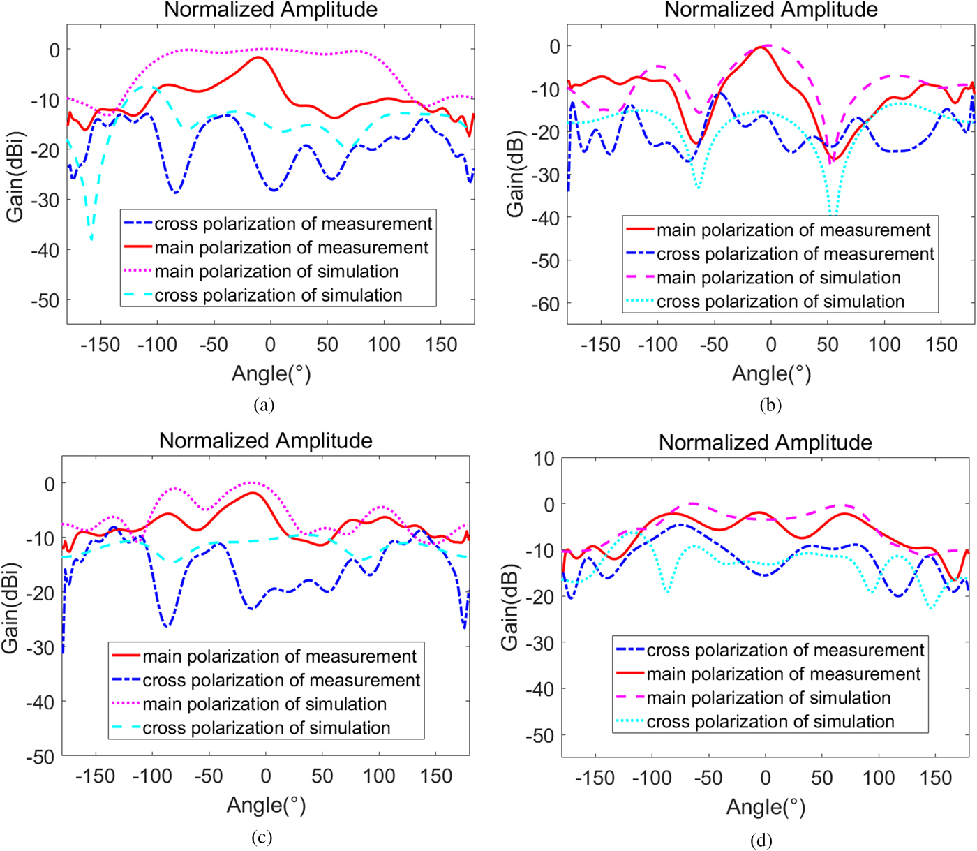
Fig. 16. The radiation pattern at 2.7 GHz, (a) the pattern of port 1 at xoz plane, (b) the pattern of port 1 at yoz plane, (c) the pattern of port 2 at xoz plane, (d) the pattern of port 2 at yoz plane.
The performance indicators of xoz plane of port 1 and the yoz plane of port 2 are better than the performance indicators of the yoz plane of port 1 and the xoz plane of port 2. That is because the antenna is end-fire antenna, whose direction of radiation is parallel to the exponential-printed dipole structure. The beam width of plane that is parallel to the exponential-printed dipole structure is larger than the beam width of plane that is vertical to the structure. Based on the antenna technical indices such as VSWR and radiation patterns, the researched dual-polarized antenna is suitable for some application fields such as passive electronic reconnaissance, passive radar, and wideband communication and detection.
Conclusion
Using polarization information processing technology to develop polarized radar is an effective approach to solve some problems. A dual-polarized antenna can receive all polarization information of electromagnetic waves. Thus, a dual-polarization antenna is a key technology in some fields such as passive radar and wideband communication and detection. In this paper, the wideband dual-polarized Vivaldi antenna with improved balun feed is presented and is composed of two Vivaldi antenna elements, which are orthogonally located. Each Vivaldi antenna element is fed by employing the electromagnetic coupling from micro-strip line to slot line. The most prominent advantage of the feed structure is that it avoids the intersection of lines and saves lines due to bending of the strip line. Performance indices can be applied to practical engineering projects. The research results in this paper can provide a useful technical reference for the practical engineering application.
Acknowledgement
This work is sponsored by the National Natural Science Foundation of China (Grant No. 61571154) and the Science Foundation of Aeronautics of China (Grant No. 20160177005).
 Lizhong Song was born in 1975. He received the Master degree and Ph.D. degree from Harbin Institute of Technology in 2001 and 2005, respectively. He is a professor and doctoral supervisor of Harbin Institute of Technology at Weihai. He focuses his academic interests on antenna design, wireless electromagnetic wave propagation, microwave technology, and radar signal processing.
 Huiyuan Zhou received the B.E. degree in Electrical Engineering and Automation from Xi'an Jiaotong University City College, China, in 2016. Currently, she is a master student in the School of Information and Electrical Engineering at Harbin Institute of Technology, China. Her research interests include dual-polarized conformal array antenna and direction of arriving estimation theory and methods.


