Introduction
Power combiners and dividers have various radar systems applications, such as power-combining amplifiers and antenna arrays [Reference Gysel1–Reference Guo, Song and Fan16]. Many researchers have proposed solutions to the joint design of compactness, low loss, high isolation, and high power density. Several waveguide power dividers with low insertion loss have been intensively investigated [Reference Becker and Oudghiri2, Reference Chu, Mo and Wu8, Reference Cano, Mediavilla, Dragas and Tazon17]. However, they suffer from large size and cannot meet the demands of high isolation with wide bandwidth. On the other hand, the power dividers designed with microstrip lines [Reference Oraizi and Sharifi3, Reference Oraizi and Ayati18, Reference Oraizi and Sharifi4–Reference Oraizi and Ayati6, Reference Oraizi and Yousefi11, Reference Song, Hu, Zhang and Zhu9, Reference Yu, Tsai and Chang13] show the potential of compact size and easy integration with active devices compared with waveguide power dividers. In [Reference Oraizi and Sharifi3], a two-way balanced Gysel power divider with wide bandwidth is proposed to modify the standard five-port divider. In [Reference Oraizi and Sharifi4, Reference Oraizi and Ayati5], Gysel power dividers with arbitrary power division ratios have been studied. Nevertheless, they are not suitable for high power combination with low loss. In [Reference Shan and Shen19], suspended stripline with high power-handling capacity is applied to reduce the loss. However, isolation is not high enough. In the previous work [Reference Guo, Song and Fan16], a suspended-stripline power divider is designed. The required isolations among the output ports are obtained by connecting floating embedded resistors in its circuit configuration. Nevertheless, these resistors are damaged easily because of missing heat transfer provision to the ground plane when the input port's power is out of balance.
In this paper, the design and fabrication of a four-way Gysel suspended-stripline power combiner with high power-combining efficiency at the X-band are described. An equivalent circuit model is used for accurate analysis and optimization. Attractive features of low loss, high isolation, and high power density are obtained. Additionally, the proposed power combiner realizes high power-combining efficiency and high power density without significantly increasing the circuit size.
Structure, analysis, and design
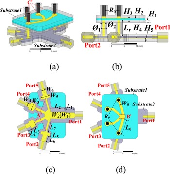
The basic configuration of the proposed four-way Gysel power combiner is shown in Fig. 1. The proposed power combiner is composed of the power-combining network and the isolation network. Suspended stripline has been used in the power-combining circuit and the insolation circuit. Air-filled coaxial lines are applied to connect the suspended-stripline power-combining circuit. One end of the inner conductor is connected to the suspended-stripline power-combining circuit through substrate 2. The connection nodes are A′ (as denoted in Fig. 1(c)). The other end is connected to the other insolation circuit through substrate 1. The connection nodes are C′ (shown in Fig. 1(a)). Four cylindrical high-power isolation resistors are located on the nodes C′, while the other ends of the resistors are soldered to the upper cavity.

Fig. 1. Proposed suspended-stripline power combiner: (a) 3D view, (b) Side view, (c) Bottom view of substrate 2, (d) Top view.
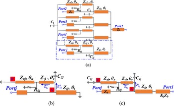
Since the proposed power combiner can be viewed as a symmetric structure, it can be analyzed by applying the even- and odd-mode equivalent-circuit method, as shown in Fig. 2. The odd-mode and even-mode equivalent circuits are shown in (Figs 2(b) and 2(c)), respectively. The analysis method can also be applied to analyze unequal power division networks. The lines with wide width result in a large capacitance at the common point, leading to circuit mismatch. As shown in Fig. 1(d), the common point B′ of the isolation network introduces lumped capacitance C 1 in the equivariant circuit. As shown in Fig. 1(c), the connection point A′ of the air-filled coaxial line and the power-combining network introduce capacitances C 2. The coaxial line of length L r is equated to an ideal transmission line of impedance Z νj and electrical length $\theta _\nu$ . The ratio of the output power P 0 to the input power Pj of the jth port is P 0/P j = K j. Kj satisfies as follows:


Fig. 2. (a) Equivalent circuit model, (b) Odd mode, (c) Even mode.
Kj can be calculated by the actual power division ratio, so the output impedance Zoj of each way is as follows:

Under equal power division ratio case, Kj = N. When odd-mode excitation is applied, the jth port is excited with power Pj, and the sum of the powers excited at the other N−1 input ports is P sumN−1 = (K j − 1)P j. The voltage at the jth input port is 180° out of phase with the voltage at the N−1 input ports. In this case, node B′ is equated to an electrical wall. The corresponding input impedances of $Z_{1j}^o$ and $Z_{2j}^o$
 in Fig. 2(b) are as follows:


where Z c2j = 1/jωC 2j, ω is the operating frequency. Then the odd-mode input reflection coefficient $\Gamma _{1j}^o$ can be characterized as follows:

Similarly, when even-mode excitation is applied, node B′ is equated to an electrical wall. The input impedances $Z_{1j}^e$ and $Z_{2j}^e$
 in Fig. 2(c) can be obtained as follows:


where Z c1j = 1/jωC j and Z c2j = 1/jωC 2j. C 1jis satisfied as follows:

Then the even-mode input reflection coefficient $\Gamma _{2j}^e$ and output reflection coefficient $\Gamma _{1j}^e$
 can be characterized as follows:


Then, the value of the input reflection coefficient Γinjand output reflection coefficient Γoutj can be found to be


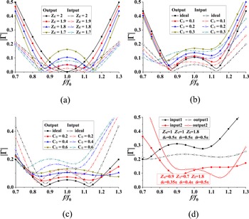
According to equations (11) and (12), the input and output reflection coefficients under different conditions can be obtained, respectively. To simplify the calculations, always let Z 0 = 1. The proposed work is a four-way balanced power division network, so K j = 4. There is only one transmission pole for the traditional Gysel power combiner (Z uj = Z vj = 1, Z t = 2, θ u = θ v = θ t = 0.5π) without node capacitance. Z t is reduced reasonably to obtain two transmission poles simultaneously for both Γinjand Γoutj as shown in Fig. 3(a). Then the bandwidth of the power combiner can be broadened. As a matter of fact, the capacitances C 1 and C2j cause the mismatch of the input and output reflection in practice, as shown in (Figs 3(b) and 3(c)). For odd mode, the resistor has power loss, when θ u = θ v = 0.5π, based on equations (3) and (4), $Z_i^o$ can be made equivalent to an resistor capacitor and inductor parallel network. So the center frequency of the input reflection coefficient shifts to a lower frequency when C1j and C2j increase. According to equation (9), the output reflection coefficient is only determined by the even-mode circuit. Based on equations (6) and (7), when θ u = θ v = 0.5π, $Z_{2j}^e \approx {1 / {j\omega ( mC_{1j} + C_{2j}) }}$
 . m is related to Zuj and Zvj. As shown in (Figs 3(b) and 3(c)), the output reflection coefficient's center frequency is constant. At the same time, they are both getting worse. As shown in Fig. 3(d), the black curves show the mismatch with both node capacitances C 1jand C 2j. The red curves Fig. 4(d) show the optimized input and output reflection coefficient. It is sufficient that Zug, Zvj, θu, and θv can be reduced to achieve a better reflection coefficient.
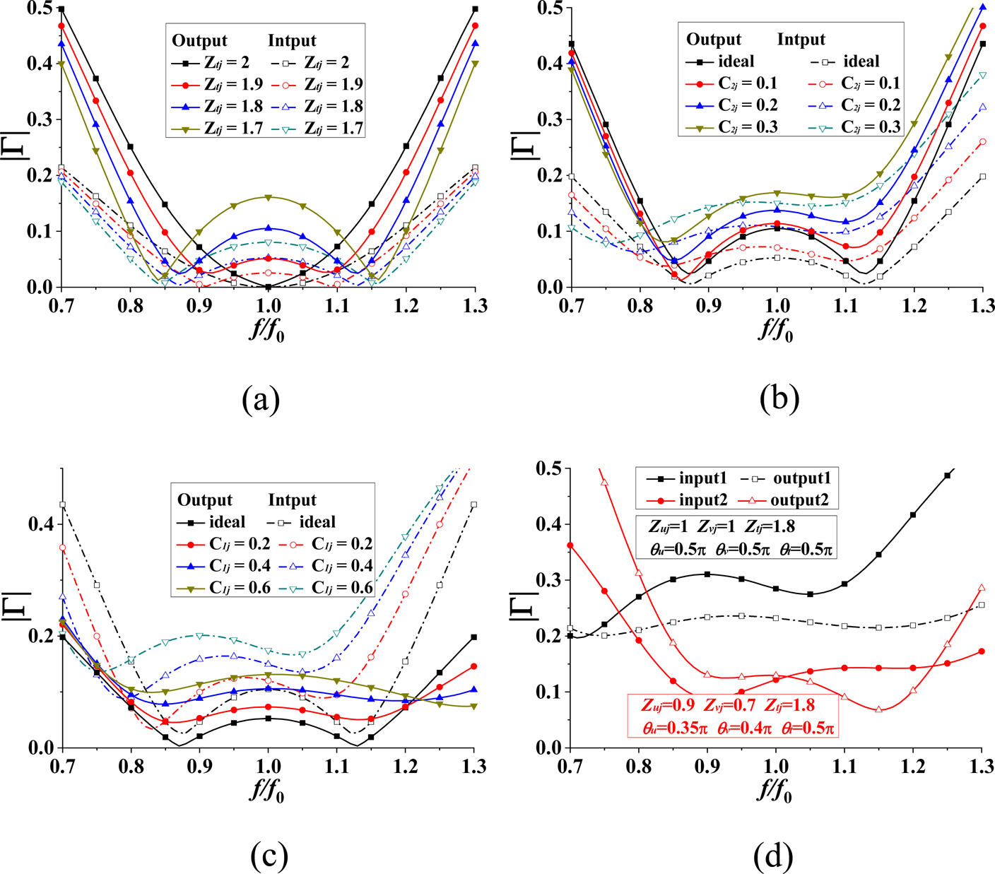
Fig. 3. Input and output reflection coefficients with varied (a) Ztj, (b) C 1j, and (c) C 2j, (d) The optimization of input and output reflection coefficient.
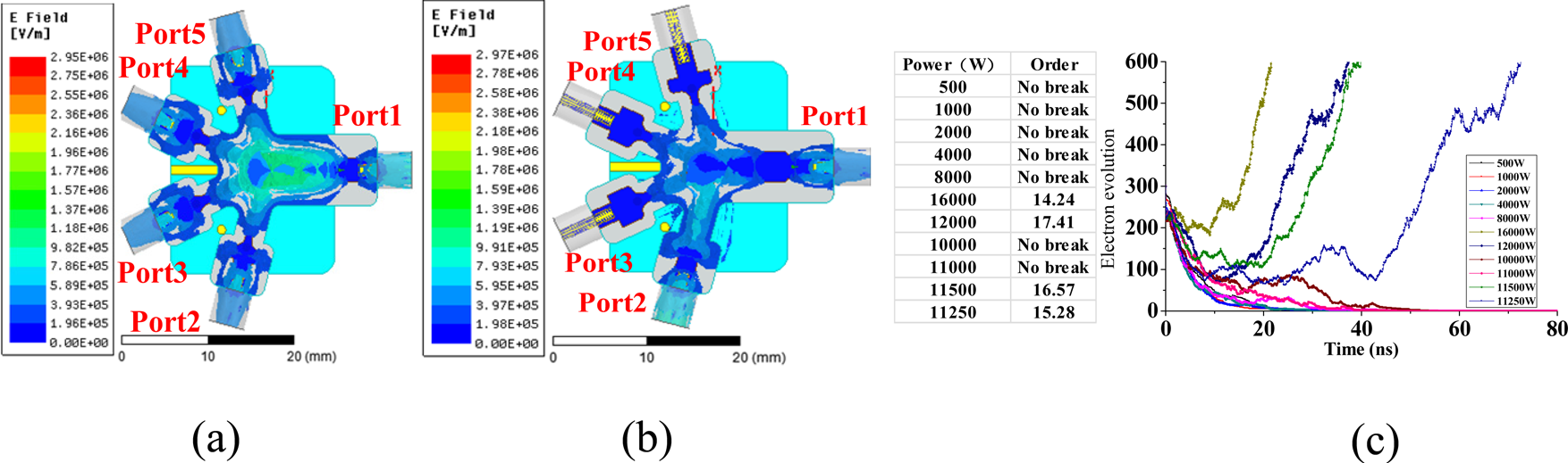
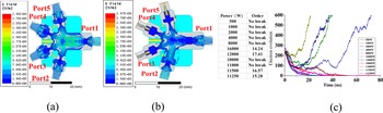
Fig. 4. Simulated electric field: (a) Input power of 25 kW from Port1, (b) Input power of 25 kW from Port2, (c) Electron evolution curve at different power.
Furthermore, the power-handling capability of the power combiner is analyzed. As shown in (Fig. 4(a) and 4(b)), when 25 kW power is applied from the power-combining port, the maximum electric field is around 2.97 × 10⁶ V/m, which is less than the simulated breakdown electric field (3 × 10⁶ V/m) of air. As shown in Fig. 4(c), the multipactor evolution process is simulated in Spark3D. The electron number increase for situations occurrence offers multipactor phenomenon taken place at about 11.5 kW (air critical breakdown power). The cross-sectional power density (CSPD) can be calculated as 3.57 kW/cm2 by using

The maximum cross-sectional area is 2.82 cm × 1.09 cm. This power combiner can be operated at high power applications.
Results and discussion
A Gysel suspended-stripline power combiner was designed according to the analysis above. It was simulated and optimized in the full-wave simulation software HFSS. The four-way power combiner has been fabricated by machining suspended-stripline in copper blocks on the substrate Taconic RF-35 with a relative dielectric constant of 3.5, the thickness of 0.508 mm, and a loss tangent of 0.0018. The final dimensions of the proposed power divider are as follows (unit: mm): L 1 = 4.95, L 2 = 7.95, L 7 = 6, L 5 = 1.57, L 6 = 3.42, L 3 = 2.72, L 4 = 2.3, L 8 = 8.91, W 8 = 1.29, W 5 = 4.72, W 6 = 2.2, W 3 = 3.9, W 4 = 2.1, W 2 = 1.29, W 1 = 1.88, Ø 1 = 1, Ø 2 = 2.6, H 1 = 0.5, H 2 = 0.508, H 3 = 1.5. The isolation resistors are 50 Ω. A photograph of the fabricated suspended-stripline power divider is shown in Fig. 5(c), and the circuit size of the area is 0.60λ g × 0.80λ g × 0.34λ g (W × L × H).

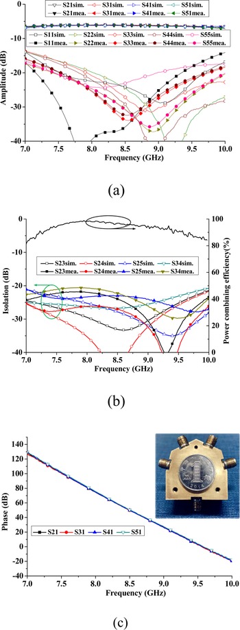
Fig. 5. Simulated and measured results: (a) Input/Output return loss and insertion loss, (b) Isolation and power combining efficiency, (c) Measured results of phase.
The fabricated power combiner has been measured by using vector network analyzer Agilent N5244A. Figure 5 shows that the measured input return loss(S 11) is greater than 20 dB from 7.15 to 9.35 GHz. Moreover, it is greater than 25 dB from 7.35 to 9.01 GHz. The measured output return loss(S nn, n = 23,4) is at least 20 dB from 7.92 to 9.75 GHz. The measured insertion loss is less than 0.36 dB, and power combining efficiency is greater than 92% from 7.39 to 9.19 GHz. The maximum power-combining efficiency of 98.8% can be observed at 8.1 GHz. Meanwhile, as shown in Fig. 5(b), the measured output isolation is greater than 20 dB from 7 to 10 GHz. The measured results and the simulated ones show a reasonable agreement with each other. The difference between the simulated and measured results is partly due to machining and assembly errors, and partly to inaccuracies of the dielectric constant of the substrate.
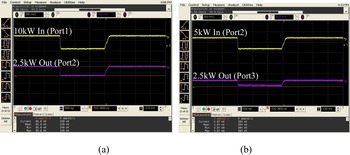
The power-combining port's power capacity has been tested under 10 kW pulse excitation with 1‰ duty cycles. In comparison, the power-dividing ports' power capacity has been tested under 5 kW pulses, as shown in Fig. 6. The test pulse power can be transmitted through the fabricated power combiner, and the electric breakdown phenomenon and a thermal breakdown do are not generated as shown in Fig. 7. The CSPD is greater than 3.57 kW/cm2. A comparison with other four-way power dividers is shown in Table 1. It can be seen that the presented Gysel power combiner has the advantages of low loss, high power-combining efficiency, relatively high isolation, high power density, and good input/output impedance matching in the operating frequency band.

Fig. 6. (a) Scenario of power capacity testing: (b) Transmission test, (c) Isolation test.

Fig. 7. Waveform of power capacity testing: (a) Transmission test, (b) Isolation test.
Table 1. Comparison between the proposed power divider and reported ones.

IRL, Input return loss (S 11); ORL, Output return loss (S nn, n = 23,4); Iso, Isolation; Ins, Insertion loss; PCE, Power-combining efficiency; CSPD, Cross-sectional power density; HPC, High power capacity.
Conclusion
In this paper, a four-way suspended-stripline Gysel power combiner is demonstrated. The developed equivalent model has been discussed. The measured results are in good agreement with the simulated ones. The proposed four-way power combiner has low insertion loss, high power-combining efficiency, high isolation, high power density, and good input/output impedance matching. It can be used in multiway high power-combining amplifiers, antenna arrays, and mixers.
Acknowledgement
This work was supported by the National Natural Science Foundation of China (Grant No. 61771094).
 Song Guo was born in Lang Fang, Hebei Province, China, in February 1993. He received his B.Sc. degree in Microelectronics from Harbin Engineering University, Harbin, Heilongjiang, China, in 2006, and is currently working toward his M.Sc. degree in Electromagnetic Fields and Microwave Technology at the UESTC (University of Electronic Science and Technology of China). His research interests include microwave and millimeter-wave power-combining technology and microwave passive component design.
 Kaijun Song received his M.S. degree in Radiophysics and a Ph.D. degree in Electromagnetic Field and Microwave Technology from the University of Electronic Science and Technology of China (UESTC), Chengdu, China, in 2005 and 2007, respectively. In 2011, he received the “New Century Excellent Talents in University Award” from the Chinese Ministry of Education. In 2015, he received the academic and technical leaders in Sichuan province. In 2019, he received the science and technology innovation talents in Sichuan province. Since 2007, he has been with the EHF Key Laboratory of Science, School of Electronic Engineering, UESTC, where he was a full professor. Since 2018, he is currently a full professor with the School of Electronic Science and Engineering, UESTC. From 2007 to 2008, he was a postdoctoral research fellow with the Montana Tech of the University of Montana, Butte, USA, working on microwave/millimeter-wave circuits and microwave remote sensing technologies. From 2008 to 2010, he was a research fellow with the State Key Laboratory of Millimeter Waves of China, Department of Electronic Engineering, City University of Hong Kong, on microwave/millimeter-wave power-combining technology and Ultra-Wideband (UWB) circuits. He was a senior visiting scholar with the State Key Laboratory of Millimeter Waves of China, Department of Electronic Engineering, the City University of Hong Kong, in November 2012. He has published more than 200 internationally refereed journal papers and conference papers. His current research fields include microwave and millimeter-wave/THz power-combining technologies, high-power solid-state microwave/millimeter-wave technologies, UWB circuits, and technologies; and microwave/millimeter-wave devices, circuits, and systems. Prof. Song is the Reviewer of tens of international journals, including IEEE Transactions and IEEE Papers.
 Yong Fan (M’05) received a B.E. degree from Nanjing University of Science and Technology, Nanjing, Jiangsu, China, in 1985 and an M.S. degree from the University of Electronic Science Technology of China, Chengdu, Sichuan, China, in 1992. He is now with the School of Electronic Engineering, University of Electronic Science and Technology of China, where he is currently a full professor. His current research interests include electromagnetic theory, millimeter-wave technology, communication, and system. He has authored and co-authored over 130 papers. Mr. Fan is a senior member of the Chinese Institute of Electronics.