


Introduction
With the rapid development in the modern wireless communication technology, antennas having multi-band and diverse polarization characteristics are required for enhancing the capabilities of wireless systems [Reference Afshinmanesh, Marandi and Shahabadi1,Reference Veysi, Kamyab and Jafargholi2]. The polarization diversity can be obtained in different ways such as (i) exciting the antenna with multi-port, thereby generating different polarizations in the same or distinct frequency bands [Reference Choi, Cho and Park3–Reference Sharma, Sarkar, Biswas, Sloan and Hu5] (ii) exciting the antenna using a single port, thereby generating multi-band behavior having different polarization at different frequency [Reference Veysi, Kamyab and Jafargholi2]. The diversified antenna can either be linearly polarized (LP) having horizontal/vertical polarization or circularly polarized (CP) having distinct sense (RHCP/LHCP) either at same or different frequencies. In certain situations, diversified antenna can be designed in such a way that it is linearly polarized at one frequency and circularly polarized at another frequency. Over the past few years, several printed dual-band dual-polarized antennas have been reported which include single-feed [Reference Afshinmanesh, Marandi and Shahabadi1,Reference Veysi, Kamyab and Jafargholi2,Reference Sabri, Amiri and Forooraghi6–Reference Mukherjee and Biswas8] and multiple-feed [Reference Tan and Wang9,Reference Wang and Du10] designs.
The dielectric resonator antennas (DRAs) in contrast to conventional metal-based radiators, offer several alluring features such as high-radiation efficiency (due to lack of surface wave and conductor losses), low dissipation loss, relatively wider bandwidth, ease of excitation etc [Reference Petosa11]. Being a volumetric radiator, it gives more design flexibility and versatility than the conventional microstrip antennas. Additionally, different modes with diverse radiation characteristics can be excited within a single dielectric resonator, which makes it an attractive candidate for diversity and multifunctional applications. In the past few years, several dual polarized DRAs have been reported for single band [Reference Gao, Feng and Zhang4,Reference Sharma, Sarkar, Biswas, Sloan and Hu5,Reference Zou and Fumeaux12–Reference Tang, Chen, Chu and Lu14] and multi-band [Reference Sun and Leung15–Reference Tang, Chen, Yang, Zhou and Li17] operation using multi-port technique, where the two ports excite the distinct polarization. However, the use of single-feed or one port can reduce the system complexity and cost of the receiver front-end in lieu of conventional dual-port systems. The development of single-feed dual-band dual-polarized DRA is in early stage and few designs have been reported [Reference Patin and Sharma18–Reference Sharma, Das and Gangwar22]. For example in [Reference Moosaei, Neshati and Rezaee19], a probe cylindrical DRA fed by SIW cavity has also been proposed for dual-band dual-linearly-polarized applications, however, the radiation efficiency is quite low. In [Reference Pan and Zheng20], dual-band and dual-sense omnidirectional circularly polarized antenna comprising of dielectric resonator and patch has been proposed. In [Reference Sharma and Gangwar21], a hybrid Z-shaped DRA having LP and CP at different frequencies has been reported for WLAN, WiMAX and satellite communication. A dual-band dual-polarized (LP+CP) system has been designed for a wireless application using a hybrid approach where an inverted regular pentagon slot produces CP and DRA produces LP [Reference Sharma, Das and Gangwar22]. All the earlier reported designs of single-feed dual-band/multi-band dual-polarized DRA are below X-band.
A single-feed dual-band dual-linearly-polarized antenna can be designed by exciting a single DRA with two orthogonal slots which is the most common excitation technique. However, as the frequency increases, the size of DR decreases for a particular value of dielectric constant. Owing to the small size of DR at high frequency, it is quite difficult to accommodate two orthogonal slots beneath the DR which makes the excitation difficult. Due to this reason, in this paper, a SIW-fed dual-frequency dual-linearly-polarized DRA is proposed in X-band, where the orthogonal polarization at distinct frequency is achieved by exciting two rectangular DRs of the same dimensions using two orthogonal slots etched on top wall of SIW. The use of SIW to feed the dielectric resonator eliminates the radiation losses of feeding network and makes it a highly efficient radiator, especially, at higher frequency [Reference Wahab, Busuioc and Naeini23]. The simulations are done using CST Microwave Studio and a prototype of the same is built for experimental verification. The proposed antenna can be scaled to higher frequency for millimeter wave applications such as next- generation 5G communication systems or it can easily be extended to a linear and 2D array using SIW- based power divider to achieve higher directivity.
Problem formulation, antenna design, analysis
Problem formulation
The main aim of this work is to design single feed dual-frequency dual-linearly-polarized DRA. In order to design the antenna, two rectangular DRs of similar dimension are excited by a narrow longitudinal and transverse slot, situated on the broad wall of SIW. However, before describing the design process of the proposed antenna, the resonant modes of an isolated rectangular dielectric resonator (RDR) are first briefly described.
An isolated RDR of relative permittivity ϵrd and dimensions W (along x-axis), L (along y-axis) and B = 2H (along z-axis) would support TEx, TEy and TEz, modes [Reference Petosa11]. With L >W >B, the resonant frequency of  ${\rm TE}^{x}_{\delta 11}$ mode is lower than
  ${\rm TE}^{y}_{1\delta 1}$ mode. Using the dielectric waveguide model, the resonant frequency of
  ${\rm TE}^{x}_{\delta 11}$ mode can be calculated by solving the following transcendental equation [Reference Petosa11]
 $$k_x \tan {\left({\displaystyle {k_x W} \over {2}} \right)} =\sqrt{(\epsilon_{rd}-1)k_{0}^{2}-k_{x}^{2}},$$
and
 $$k_y = {\displaystyle {m \pi} \over {L}} \quad {\rm and} \quad k_z = {\displaystyle {n \pi} \over {B}} \quad {\rm where} \quad m=n=1,$$
where, kx, ky, and kz are the wavenumbers along the x-, y-, and z-directions and are related as
 $$k_{x}^{2}+k_{y}^{2}+k_{z}^{2}= \epsilon_{rd} k_{0}^{2},$$
where, k 0 denotes the free space wavenumber. The resonant frequency of  ${\rm TE}^{y}_{1\delta 1}$ mode can be calculated in the same way as above. Based on the above equations, different RDRA dimensions are possible for a particular value of dielectric constant such that both the modes resonates in X-band. Some of the possible dimensions are given in Table 1. For the present design, we have chosen W = 7 mm, L = 10 mm, and H = 3.81 mm.
Table 1. Possible RDRA dimensions for ϵrd = 10.2

Once the antenna dimensions are chosen, an appropriate feeding network is designed to facilitate the dual-frequency dual-polarized operation as described in the next section.
Antenna design and analysis
In order to design SIW- fed dual-frequency dual-linearly-polarized DRA, we first design two different configurations of SIW fed DRA. In the first configuration (refer Fig. 1(a)), DR is excited through a narrow longitudinal slot etched on the broad wall of the SIW and in the second configuration (refer Fig. 1(b)), a narrow transverse slot is used to excite the rectangular DR. The DR under investigation is made of Rogers RT/Duroid 6010 of relative permittivity 10.2 and has dimensions W × L × H. The dimensions of the rectangular DR are chosen such that the operating frequency of both the configurations fall in X-band. The X-band SIW presented here is designed on Rogers RT/Duroid 5880 substrate of dielectric constant 2.2 and thickness 0.787 mm. The two rows of metallic vias are placed a SIW distance apart which is calculated using the following equation [Reference Kordiboroujeni and Bornemann24]
 $$a_{SIW}=W_{equi}+p(0.766e^{(0.4482d/p)}-1.176e^{(-1.214d/p)}),$$
where p is the pitch between the vias, d is the diameter of vias and W equi is the effective waveguide width determined as [Reference Kordiboroujeni and Bornemann24]
 $$W_{equi}={\displaystyle {c} \over 2f_c \sqrt {\epsilon_{rs}}},$$
where ϵrs is the substrate permittivity. The diameter d and pitch p are chosen in order to maintain the minimum leakage of energy through sidewall of SIW [Reference Kordiboroujeni and Bornemann24] and the width of SIW (a SIW) is chosen for the single fundamental TE10 mode propagation.

Fig. 1. Different antenna configurations and simulated response (a) SIW-fed DRA using longitudinal slot (b) SIW- fed DRA using transverse slot (c) Reflection coefficient (d) Input impedance plot for longitudinal slot-fed DRA (e) Input impedance plot for transverse slot-fed DRA.
Figure 1(c) shows the reflection coefficient of the two configuration of SIW-fed DRA and the corresponding input impedance curve is depicted in Figs 1(d) and 1(e). The longitudinal slot excites the DRA in  ${\rm TE}^{x}_{\delta 11}$ mode whereas the transverse slot excite the DRA in TE
 $^{y}_{1\delta 1}$ mode. The theoretical resonant frequency calculated using (1)–(3) for
  ${\rm TE}^{x}_{\delta 11}$ and
  ${\rm TE}^{y}_{1\delta 1}$ mode is 8.90 GHz and 9.77 GHz, respectively whereas the simulated resonant frequency is 8.53 GHz and 10.74 GHz, respectively. The shift in the theoretical and simulated frequency is due to the fact that mathematical analysis considers infinite ground plane and it did not account the effect of slot [Reference Wahab, Busuioc and Naeini23]. In case of longitudinal slot excitation, extra vias are embedded near the slot. These vias helps in the impedance matching [Reference Wahab and Naeini25] which is clearly inferred from Fig. 1(c).
Next, in order to design dual-frequency dual-linearly-polarized antenna, both the longitudinal and transverse slot are accommodated on the broad wall of the same SIW as shown in Fig. 2. This configuration will excite two similar DRs at distinct frequency simultaneously to achieve dual-frequency dual-polarized response. The element DR1 is excited by a narrow longitudinal slot of dimension L ST × W ST located at a distance of X L from the shorting wall and the element DR2 is excited by a narrow transverse slot of dimension L SL × W SL located at a distance of X T from the shorting wall.

Fig. 2. Geometry of the proposed dual-frequency dual-polarized DRA (a) Isometric view (b) Top view without DR.
Figure 3 shows the effect of longitudinal slot length L SL and its position X L on the reflection coefficient. It is evident from the figure that the change in L SL affects the matching of lower frequency band whereas the matching of upper frequency band is not affected much and S 11 remains well below −10 dB for different values of L SL. Similarly, the change in the value of X L affects only the matching of the lower band. The similar variation in the response of the antenna is observed for different slot width. Figure 4 shows the effect of transverse slot length L ST and its position X T on the reflection coefficient of the antenna. It is observed from the figure that, changing the transverse slot length affects the matching of upper frequency band whereas the S 11 remains well below −10 dB for lower frequency band. The change in the slot position X T affects the matching of upper band whereas it hardly affects the lower band.

Fig. 3. Simulated reflection coefficient of dual-frequency dual-polarized DRA for different values of (a) longitudinal slot length L SL (b) slot position X L.

Fig. 4. Simulated reflection coefficient of dual-frequency dual-polarized DRA for different values of (a) transverse slot length L ST (b) slot position X T.
The above parametric study confirms that the element DR1 is responsible for lower resonance whereas the element DR2 is responsible for upper frequency.
Figures 5(a) and 5(b) shows the current distribution in SIW at 8.52 GHz and 10.62 GHz, respectively. It is observed that at both the frequency the current distribution resembles the current distribution of TE10 mode of the substrate integrate waveguide which helps in the excitation of DR through the narrow slots.
To gain insight into the resonant modes responsible for radiation, the simulated modal E-field distribution at 8.58 GHz and 10.62 GHz are portrayed in Figs 5(c) and 5(d). From the figure, it is evident that  ${\rm TE}^{x}_{\delta 11}$ mode is excited at 8.58 GHz whereas
  ${\rm TE}^{y}_{1\delta 1}$ is excited at 10.62 GHz. With reference to the coordinate system shown in Fig. 2, the longitudinal slot excites DR1 in
  ${\rm TE}^{x}_{\delta 11}$ mode, generating linear vertical polarization at the lower frequency whereas the transverse slot excites DR2 in
  ${\rm TE}^{y}_{1\delta 1}$ mode, thereby producing linear horizontal polarization at the upper frequency.

Fig. 5. (a) Current distribution in SIW at (a) 8.58 GHz (b) 10.62 GHz and Electric field distributions in the rectangular DR at (a) 8.58 GHz (yz-plane) (b) 10.62 GHz (xz-plane).
Antenna fabrication and experimental results
To validate the proposed design, a prototype of DRA is built using Rogers RT/Duroid 6010 of dielectric constant 10.2 with design parameters: L = 10 mm, W = 7 mm, H = 3.81 mm, p = 1.6 mm, d = 1 mm, a SIW = 16.12 mm, L ST = 9 mm, W ST = 0.25 mm, L SL = 5 mm, W SL = 1 mm, X L = 29 mm, X T = 10.5 mm, p m = 2 mm. The rectangular DRs of desired dimension are cut from Rogers RT/Duroid 6010 (ϵrd = 10.2) having thickness of 1.27 mm with the help of abrasive waterjet machine. The pieces are then glued together using commercially available adhesive to get the desired height. The measurement of the reflection coefficient is carried out using Aglient E5071C vector network analyzer. Figure 6 depicts the comparison between the simulated and measured reflection coefficient of the proposed SIW fed dual-frequency dual-linearly-polarized DRA. The measured resonant frequencies of two modes are 8.54 GHz and 10.60 GHz, which fairly agree with the simulated values of 8.58 GHz and 10.62 GHz. The simulated and measured impedance bandwidth (for S 11<−10 dB) of lower band is 6.48% (8.21–8.76 GHz) and 6.76% (8.14–8.71 GHz), respectively and the corresponding data for the upper band is 8.2% (10.17–11.04 GHz) and 6.76% (10.29–11.01 GHz), respectively. A little deviation between the simulated and measured results can be attributed to fabrication imperfection, alignment of DR, the inevitable air gap between the DR and the feeding structure. Though a very thin layer of glue is used but it might affect the measurement as well.

Fig. 6. (a) Fabricated prototype of the proposed antenna (b) Simulated and measured response of the proposed dual-frequency dual-polarized DRA.
Figure 7 shows the comparison between the simulated and measured normalized radiation pattern of the proposed antenna at two operating frequencies. The proposed antenna radiates along the broadside direction with cross polarization level better than −10 dB in both xz- and yz-plane. The simulated and measured gain of antenna ranges from 5.32 to 6.00 dBi and 5.37–6.24 dBi, respectively at lower band whereas in upper band it varies from 6.14 to 7.82 dBi in simulation and 5.62–7.96 dBi in measurement as shown in Fig. 8. The radiation efficiency of the antenna is 94% at lower operating frequency and 91% at upper operating frequency.

Fig. 7. Normalized radiation pattern of the proposed antenna (a) yz-plane (lower frequency) (b) yz-plane (upper frequency) (c) xz-plane (lower frequency) (d) xz-plane (upper frequency).
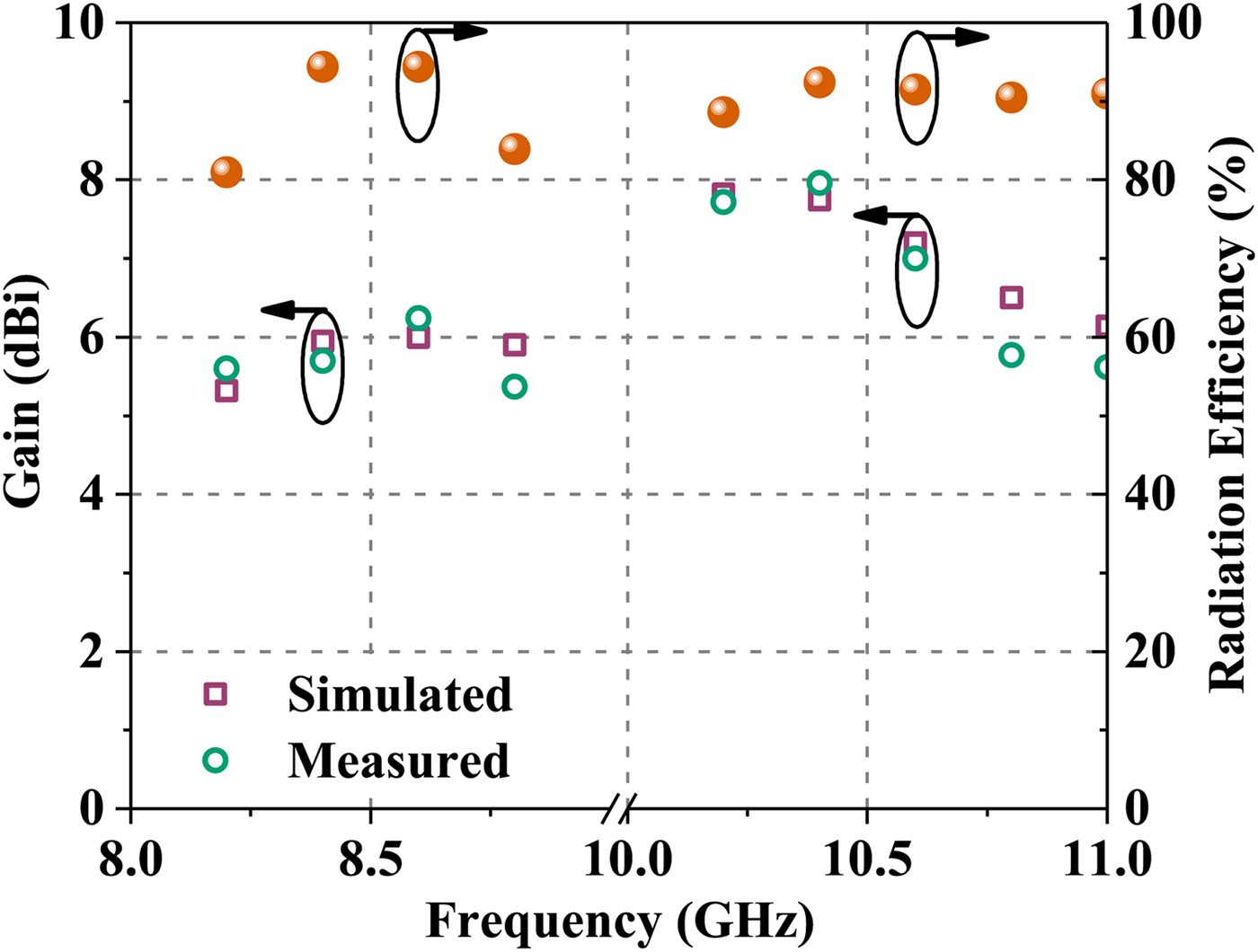
Fig. 8. Simulated and measured gain and simulated radiation efficiency of the proposed antenna.
A very few DR- based single feed dual-frequency dual-linearly-polarized antennas were available in the open literature. Table 2 shows the comparison of the proposed antenna with some other related antennas.
Table 2. Comparison of the proposed antenna with the other single-fed dual-polarized dual-band DRAs

The bold values highlight the proposed antenna as compared to other related antennas. NA, not available.
†a Average gain.
Conclusion
A novel substrate integrated waveguide fed dual-frequency dual-polarized rectangular DRA has been proposed. The polarization diversity at distinct frequency has been achieved by exciting two rectangular dielectric resonators of same dimension in  ${\rm TE}^{x}_{\delta 11}$ and
  ${\rm TE}^{y}_{1\delta 1}$ mode through narrow longitudinal and transverse slot, respectively etched over the substrate integrated waveguide. The
  ${\rm TE}^{x}_{\delta 11}$ mode generates linear vertical polarization at lower frequency while the
  ${\rm TE}^{y}_{1\delta 1}$ mode produces linear horizontal polarization at higher frequency. The −10 dB impedance bandwidth of the proposed antenna is 6.76% in each band. The antenna exhibits broadside radiation at both the operating frequency with cross- polarization level better than −10 dB in both the planes. The gain of antenna varies from 5.37 to 6.24 dBi in lower band and 5.62–7.96 dBi in the upper band. The proposed antenna could be suitable for two-way satellite internet systems, modern radar systems. Moreover, it can be scaled to higher frequency for millimeter wave applications such as next generation 5G communication system.
 Abhishek Sharma received the B. Tech. degree in Electronics and Communication Engineering from Shri Mata Vaishno Devi University, Jammu, India, in 2010 and M. Tech. degree in RF and Microwave Engineering from AIACTR, New Delhi, India, in 2013. Currently, he is pursuing the Ph.D. degree from Indian Institute of Technology Kanpur, Kanpur, India. He has authored/co-authored nine peer-reviewed journals and 16 national/international conference papers. His current research interests include dielectric resonator antennas, MIMO antennas, and SIW-based leaky wave antennas. He is a Graduate student member of IEEE and student member of European Microwave Association. Mr. Sharma has served as Treasurer and Chapter Chair of IEEE MTT-S Student Branch Chapter, IIT Kanpur, in 2015 and 2016, respectively.
 Anirban Sarkar received the B. Tech. degree in Electronics and Communication Engineering from Hooghly Engineering and Technology College, Kolkata, India, in 2011 and M. E. degree in Microwave Communication from Indian Institute of Engineering Science and Technology, Shibpur, India in 2013. Currently, he is pursuing the Ph.D. degree from Indian Institute of Technology Kanpur, Kanpur, India. His current research interests include SIW-based circuits, SIW-based leaky wave antennas and reconfigurable antennas. He is a student member of IEEE. Mr. Sarkar has served as webmaster of IEEE APS Student Branch Chapter, IIT Kanpur and currently holds the position of Vice-Chair in IEEE APS Student Branch Chapter, IIT Kanpur, and secretary in IEEE MTT-S Student Branch Chapter, IIT Kanpur.
 Animesh Biswas was born in Malbazar, India, in April 1960. He received the M.Tech. degree in Microwave and Radar Engineering from the Indian Institute of Technology, Kharagpur, India, in 1982, and the Ph.D. degree ine Electrical Engineering from the Indian Institute of Technology, New Delhi, India, in 1989. From 1982 to 1992, he was a Research and Development Engineer with the Indian Telephone Industries Ltd., Bangalore, India, where he was involved in the area of microwave circuits. From 1989 to 1990, he was a Post-Doctoral Fellow with Oregon State University, where he was involved in characterizing multiconductor lines in layered medium. In 1992, he joined the Electrical Engineering Department, Oregon State University, as a faculty member. He is currently a Professor with the Department of Electrical Engineering, Indian Institute of Technology, Kanpur, India. He has served as a technical consultant for M/S COMDEV Europe, and was involved in development of multimode DR filters and diplexers. His current research includes modeling of microwaves circuits, RF integrated circuits (RFICs), and numerical methods for solving electromagnetic problems. Dr. Biswas is a Fellow of the Institution of Electronics and Telecommunication Engineers (IETE), India and senior member of IEEE, USA.
 M. Jaleel Akhtar received the Ph.D./Dr. Ing. degree in electrical engineering from the Otto-von-Guericke University of Magdeburg, Magdeburg, Germany, in 2003. From 1994 to 1997, he was a Scientist with the Central Electronics Engineering Research Institute, Pilani, India, where he was mainly involved with the design and development of high-power microwave tubes. In March 2009, he joined the Department of Electrical Engineering, Indian Institute of Technology Kanpur, India, where he is currently an Associate Professor. He has authored two books, two book chapters, and more than 100 papers in various peer-reviewed international journals and conference proceedings. He holds one patent on coplanar-based RF sensors. His current research interests include microwave imaging and nondestructive testing, RF sensors, electromagnetic modeling and testing of artificial dielectrics and metamaterials, ultra-wideband antennas for imaging, design and development of frequency selective surfaces, and conventional materials-based electromagnetic absorbers for radar cross-section reduction, and design of RF filters and components using the electromagnetic inverse scattering. Dr. Akhtar is a Fellow of the IETE, New Delhi, India. He is a Life Member of the Indian Physics Association and the Indo-French Technical Association. He is the Chair of the IEEE Microwave Theory and Techniques Society Uttar Pradesh Chapter and the Vice-Chair of the IEEE Uttar Pradesh Section.


