


1.0 INTRODUCTION
Impact performance is a particularly important consideration in the design of laminated composite structures. Low-energy impacts or minor object drops, like tools during assembly or maintenance operation, can cause significant damage in terms of matrix cracking, delamination or fibre breakage, which may be barely visible from the surface by visual inspection. It has been shown that such internal damage can lead to drastic reductions of compressive stiffness and load-carrying capability(Reference Hull and Shi1). The ability to predict specifics of impact damage is therefore essential for efficient damage tolerance design of composite primary aeronautical structures.
A number of failure mechanisms, which interact in a complicated way, are involved when a composite structure suffers a low-velocity impact. The initiation and propagation of these failure mechanisms depend on a large set of impact parameters such as the structural configuration, properties of the projectile and the environmental conditions. Due to all of these facts, numerical damage models for all failure modes are required to be developed to accurately capture specific failure mechanisms in the impact event. In recent years, Continuum Damage Mechanics (CDM) has drawn an increasing attention for the potential applications in simulating impact damage for composite materials(Reference Hou, Petrinic and Ruiz2-Reference Chang and Chang4). CDM predicts damage initiation in the undamaged material with the corresponding stress or strain damage initiation criteria and degrades the material stiffness to simulate the propagation of damage. An approach for accurately modelling interlaminar and intralaminar fracture mechanisms is required when simulating impact in laminated composites.
The impact damage is classically divided in the intralaminar damage (i.e. matrix cracking, fibre breakage and fibre-matrix interface debonding) and the interlaminar damage (i.e. delamination). The Hashin failure criterion has been used extensively for intralaminar damage modes in industry, although it cannot accurately predict the intralaminar damage initiation, especially matrix compressive failure. In a World Wide Failure Exercise(Reference Hinton, Kaddour and Soden5,Reference Soden, Kaddour and Hinton6) , a study was conducted to compare the predictive capabilities of a number of failure criteria for Uni-Directional (UD) laminates. It indicates that, out of current failure criteria judged against experimental evidence, the one developed by Puck(Reference Knops7) gives the best results and seems to be one of the most potent failure criteria at that time. Thus, several researchers attempt to apply the Puck failure criterion to estimate the matrix damage initiation in the low-velocity impact event. In Puck's theory, an Inter-Fibre Fracture (IFF) generates a macroscopically planar fracture plane, and the angle of this IFF plane is related to the actual stress state. However, a fracture plane angle, observed experimentally under uniaxial compressive loading rather than impact, was chosen by Faggiani and Falzon(Reference Faggiani and Falzon8) and Shi et al.(Reference Shi, Swait and Soutis9) to predict matrix compressive damage. Nowadays both intralaminar and interlaminar damage types were usually considered separately: the intralaminar damage was modelled thanks to different kinds of interlaminar damage models, while the interlaminar damage was often modelled by the Cohesive Zone Model (CZM). This CZM approach was widely used for delamination modelling issues and proved its effectiveness. However, cohesive elements should be placed accurately at each interface between plies in the impact damage analysis, and Raimondo et al(Reference Raimondo, Iannucci and Robinson10) indicated that the use of interface cohesive elements between each ply of a typical standard composite impact coupon with more than 16 plies would result in increasing the central processing unit (CPU) time significantly. Moreover, the simulation of progressive delamination using cohesive elements poses numerical difficulties related with the proper definition of stiffness of the cohesive layer and the requirement of extremely refined meshes(Reference Turon, Davila and Camanho11). The interface cohesive elements, suffering from mentioned limitations, therefore can be hardly used in the design and analysis of components and structures for aerospace.
Basically the impact-induced delamination is generated by two types of critical cracks as the inner shear crack and the surface bending crack. An interesting delamination growth criterion has been proposed by Choi et al.(Reference Choi, Downs and Chang12,Reference Choi, Downs and Chang13) to correctly simulate the experimental observations. In the Choi's delamination criterion, it is considered that the impact-induced delamination will occur, only when the in-plane bending stress and the interlaminar shear stresses governing the delamination growth mechanisms through the thicknesses of the upper and lower ply groups of the interface reaches a critical value. This criterion has been used in the low-velocity impact damage analysis of the composite laminate and shell structures by Her and Liang(Reference Her and Liang14). The above delamination criterion, however, still has an evident drawback in that an equivalent role is played by lower or upper ply while the bending effect induced by an impact gives the lower ply a more important role in the delamination progression(Reference Bouvet, Castanie and Bizeul15).
In this paper, the impact response of the carbon fibre-reinforced epoxy matrix composite laminates has been investigated, experimentally and numerically. Realising the importance of numerical accuracy and efficiency, an attempt has been made to develop a new CDM-based method for the prediction of laminated components and structures with a large number of plies under low-velocity impact loading. The Puck criterion for 3D stress states, with corresponding stiffness degradation technology based on the angle of the fracture plane, is adopted to estimate the initiation of intralaminar damage including matrix cracking and fibre breakage. Also, for modelling the delamination, a new delamination criterion is proposed according to the interlaminar delamination mechanism. Furthermore, solid elements representing stacks of several plies, in order to reduce significantly the computational amount required to perform the simulation, have been established by interpolation on the strains of element integration points. The damage model is implemented in the user material subroutine of the ABAQUS/explicit program, VUMAT, and used for the impact analysis using the ABAQUS/explicit program. Drop weight impact tests are performed in a range of different impact energies and the overall damage area is inspected using ultrasound C-scan. Finally, the impact behaviour and internal damage of composite laminates that depend on the impact energy level are also investigated.
2.0 DAMAGE MODEL OF COMPOSITE MATERIALS
2.1 Failure criterion for the intralaminar damage
The damage of composite laminates induced by impact loading is often a complex mixture consisting of matrix cracking, delamination and fibre breakage. The Puck 3D failure criterion, which treats the UD laminate as transverse isotropic and brittle, is adopted by authors to predict the intralaminar impact damage. The Puck's theory clearly distinguishes between two fracture types of a UD laminate: FF and IFF. In an elementary approach, those two cases are treated with mutually independent criteria. Assuming only the stress component in the fibre direction, σ1, is relevant for FF, Puck's FF criterion can be expressed as:
Fibre tension fracture (σ1 ⩾ 0):
 $$\begin{equation}
{f_{E\;{\rm{FF}}}} = \frac{{{\sigma _1}}}{{R_\parallel ^t}} \ge 1
\end{equation}$$
$$\begin{equation}
{f_{E\;{\rm{FF}}}} = \frac{{{\sigma _1}}}{{R_\parallel ^t}} \ge 1
\end{equation}$$
Fibre compression fracture (σ1 < 0):
 $$\begin{equation}
{f_{E\;{\rm{FF}}}} = - \frac{{{\sigma _1}}}{{R_\parallel ^c}} \ge 1,
\end{equation}$$
$$\begin{equation}
{f_{E\;{\rm{FF}}}} = - \frac{{{\sigma _1}}}{{R_\parallel ^c}} \ge 1,
\end{equation}$$
where Rt ∥ and Rc ∥ denote the tensile and compressive strengths of the UD laminate in the fibre direction.
The physical foundation for Puck's IFF criterion is given by Mohr's fracture hypothesis for brittle materials. It states that intrinsically brittle failure leading to fracture in a plane which is parallel to the fibre direction of the UD laminate and defined by the fracture plane angle, θ, as shown in Fig. 1. Note that the coordinate system 1-2-3 and l-n-t are the global laminate coordinate system and the fracture plane coordinate system, respectively. The material fracture plane that offers the lowest failure resistance is determined by the stresses acting on that plane. Consequently, the action plane-related stresses (σ n , τ nl and τ nt ) are only a function of the fracture plane angle and derived from the applied stresses (σ2, σ3, τ12, τ13 and τ23) as follows:
 $$\begin{equation}
\begin{array}{@{}l@{}} {\sigma _n}(\theta ) = {\sigma _2}\,{\rm{co}}{{\rm{s}}^2}\theta + {\sigma _3}\,{\rm{si}}{{\rm{n}}^2}\theta + 2{\tau _{23}}{\rm{sin}}\,\theta \,{\rm{cos}}\theta \\ {\tau _{nt}}(\theta ) = \left( {{\sigma _3} - {\sigma _2}} \right)\,{\rm{sin}}\,\theta {\rm{cos}}\theta + {\tau _{23}}({\rm{co}}{{\rm{s}}^2}\theta - {\rm{si}}{{\rm{n}}^2}\theta )\\ {\tau _{nl}}(\theta ) = {\tau _{13}}\,{\rm{sin}}\theta + {\tau _{12}}\,{\rm{cos}}\theta \end{array}
\end{equation}$$
$$\begin{equation}
\begin{array}{@{}l@{}} {\sigma _n}(\theta ) = {\sigma _2}\,{\rm{co}}{{\rm{s}}^2}\theta + {\sigma _3}\,{\rm{si}}{{\rm{n}}^2}\theta + 2{\tau _{23}}{\rm{sin}}\,\theta \,{\rm{cos}}\theta \\ {\tau _{nt}}(\theta ) = \left( {{\sigma _3} - {\sigma _2}} \right)\,{\rm{sin}}\,\theta {\rm{cos}}\theta + {\tau _{23}}({\rm{co}}{{\rm{s}}^2}\theta - {\rm{si}}{{\rm{n}}^2}\theta )\\ {\tau _{nl}}(\theta ) = {\tau _{13}}\,{\rm{sin}}\theta + {\tau _{12}}\,{\rm{cos}}\theta \end{array}
\end{equation}$$

Figure 1. Definition of the fracture plane angle and plane-related stresses.
According to the fracture plane's normal stress component, σ n , two cases of IFF are distinguished, being tensile or compressive. It leads to the two central expressions of Puck's IFF criterion:
Interfibre tension fracture (σ n ⩾ 0):
 $$\begin{equation}
{f_{{\rm{IFF}}}}\left( \theta \right) = \left[ {{{\left( {\frac{1}{{R_ \bot ^t}} - \frac{{p_{ \bot \psi }^t}}{{R_{ \bot \psi }^A}}} \right)}^2}\sigma _n^2\left( \theta \right) + {{\left( {\frac{{{\tau _{nt}}\left( \theta \right)}}{{R_{ \bot \bot }^A}}} \right)}^2} + } \right.{\left. {{{\left( {\frac{{{\tau _{nl}}\left( \theta \right)}}{{{R_{ \bot \parallel }}}}} \right)}^2}} \right]^{\frac{1}{2}}} + \frac{{p_{ \bot \psi }^t}}{{R_{ \bot \psi }^A}}{\sigma _n}\left( \theta \right)
\end{equation}$$
$$\begin{equation}
{f_{{\rm{IFF}}}}\left( \theta \right) = \left[ {{{\left( {\frac{1}{{R_ \bot ^t}} - \frac{{p_{ \bot \psi }^t}}{{R_{ \bot \psi }^A}}} \right)}^2}\sigma _n^2\left( \theta \right) + {{\left( {\frac{{{\tau _{nt}}\left( \theta \right)}}{{R_{ \bot \bot }^A}}} \right)}^2} + } \right.{\left. {{{\left( {\frac{{{\tau _{nl}}\left( \theta \right)}}{{{R_{ \bot \parallel }}}}} \right)}^2}} \right]^{\frac{1}{2}}} + \frac{{p_{ \bot \psi }^t}}{{R_{ \bot \psi }^A}}{\sigma _n}\left( \theta \right)
\end{equation}$$
Interfibre compression fracture (σ n < 0):
 $$\begin{equation}
{f_{{\rm{IFF}}}}\left( \theta \right) = \left[ {{{\left( {\frac{{p_{ \bot \psi }^c}}{{R_{ \bot \psi }^A}}{\sigma _n}\left( \theta \right)} \right)}^2} + {{\left( {\frac{{{\tau _{nt}}\left( \theta \right)}}{{R_{ \bot \bot }^A}}} \right)}^2} + } \right.{\left. {{{\left( {\frac{{{\tau _{nl}}\left( \theta \right)}}{{{R_{ \bot \parallel }}}}} \right)}^2}} \right]^{\frac{1}{2}}} + \frac{{p_{ \bot \psi }^c}}{{R_{ \bot \psi }^A}}{\sigma _n}\left( \theta \right),
\end{equation}$$
$$\begin{equation}
{f_{{\rm{IFF}}}}\left( \theta \right) = \left[ {{{\left( {\frac{{p_{ \bot \psi }^c}}{{R_{ \bot \psi }^A}}{\sigma _n}\left( \theta \right)} \right)}^2} + {{\left( {\frac{{{\tau _{nt}}\left( \theta \right)}}{{R_{ \bot \bot }^A}}} \right)}^2} + } \right.{\left. {{{\left( {\frac{{{\tau _{nl}}\left( \theta \right)}}{{{R_{ \bot \parallel }}}}} \right)}^2}} \right]^{\frac{1}{2}}} + \frac{{p_{ \bot \psi }^c}}{{R_{ \bot \psi }^A}}{\sigma _n}\left( \theta \right),
\end{equation}$$
with
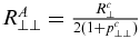 $R_{ \bot \bot }^A = \frac{{R_ \bot ^c}}{{2( {1 + p_{ \bot \bot }^c} )}}$
and
$R_{ \bot \bot }^A = \frac{{R_ \bot ^c}}{{2( {1 + p_{ \bot \bot }^c} )}}$
and
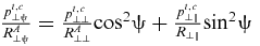 $\frac{{p_{ \bot \psi }^{t,c}}}{{R_{ \bot \psi }^A}} = \frac{{p_{ \bot \bot }^{t,c}}}{{R_{ \bot \bot }^A}}{\rm{co}}{{\rm{s}}^2}\psi + \frac{{p_{ \bot \parallel }^{t,c}}}{{{R_{ \bot \parallel }}}}{\rm{si}}{{\rm{n}}^2}\psi $
with
$\frac{{p_{ \bot \psi }^{t,c}}}{{R_{ \bot \psi }^A}} = \frac{{p_{ \bot \bot }^{t,c}}}{{R_{ \bot \bot }^A}}{\rm{co}}{{\rm{s}}^2}\psi + \frac{{p_{ \bot \parallel }^{t,c}}}{{{R_{ \bot \parallel }}}}{\rm{si}}{{\rm{n}}^2}\psi $
with
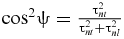 ${\rm{co}}{{\rm{s}}^2}\psi = \frac{{\tau _{nt}^2}}{{\tau _{nt}^2 + \tau _{nl}^2}}$
In Equations (4) and (5), Rt ⊥ and Rc ⊥ are the tensile and compressive strengths of the UD laminate in the transverse direction. R ⊥∥ denotes the longitudinal or transverse shear strengths. Some multiaxial tests are required to measure physically realistic values of inclination parameters, pt ⊥∥, pc ⊥∥, pt ⊥⊥and pc ⊥⊥. The present analysis follows the recommendations given in Ref. 16 for the specific values of 0.35, 0.30, 0.27 and 0.27, respectively.
It is clear from Equations (4) and (5) that IFF failure can only be assessed if the fracture plane angle is known. The actual fracture plane, following Puck's hypothesis, is the plane with the highest risk of fracture. Hence, in the general case of three-axial stress states, the calculation of the actual fracture plane angle, θ fp , turns into a search for the global maximum of the function f IFF(θ) within the interval [ − 90°, 90°]. The specific angle θ fp of the actual fracture plane can be identified numerically in Equation (6). When the value of the function f IFF(θ fp ) reaches 1.0, IFF of the UD laminate is considered to occur.
 $$\begin{equation}
{\left[ {{f_{{\rm{IFF}}}}(\theta )} \right]_{{\rm{max}}}} = {f_{{\rm{IFF}}}}({\theta _{fp}})
\end{equation}$$
$$\begin{equation}
{\left[ {{f_{{\rm{IFF}}}}(\theta )} \right]_{{\rm{max}}}} = {f_{{\rm{IFF}}}}({\theta _{fp}})
\end{equation}$$
Following Puck's suggestions(Reference Knops7,Reference Puck, Kopp and Knops20) , a sufficiently large number of angles θ between –90° and 90° has to be substituted into f IFF(θ) one after another until the global maximum of f IFF(θ) is found, which will, no doubt, introduce a lot of times for loop iterations in one FE element. In order to improve computational efficiency, some researchers(Reference Faggiani and Falzon8,Reference Shi, Swait and Soutis9) simplify the angle of the fracture plane as the one that can be determined from uniaxial compression tests (θ fp ≈ 53°). Obviously, this simplified method neglects the influence of different stress states. Thus, taking into account the influence of the stress states and the computational efficiency and accuracy, the Golden Section Search, as an efficient and accurate numerical algorithm for evaluation of the global maximum of f IFF(θ), is adopted to the problem of finding the actual fracture plane angle. Within the interval [ − 90°, 90°], the extreme is found by successively narrowing the search range by evaluating the function at point θ1, θ2 and θ3. The distances of above three points fulfil Golden Ratios, which gives the approach its name. Suppose that θ1 and θ2 (θ1 < θ2) are known, the angle θ3 is chosen by means of
 $$\begin{equation}
\frac{{{\theta _2} - {\theta _3}}}{{{\theta _3} - {\theta _1}}} = \frac{{1 + \sqrt 5 }}{2}
\end{equation}$$
$$\begin{equation}
\frac{{{\theta _2} - {\theta _3}}}{{{\theta _3} - {\theta _1}}} = \frac{{1 + \sqrt 5 }}{2}
\end{equation}$$
And an additional point θ4 can be chosen by
 $$\begin{equation}
\frac{{{\theta _2} - {\theta _4}}}{{{\theta _4} - {\theta _3}}} = \frac{{1 + \sqrt 5 }}{2}
\end{equation}$$
$$\begin{equation}
\frac{{{\theta _2} - {\theta _4}}}{{{\theta _4} - {\theta _3}}} = \frac{{1 + \sqrt 5 }}{2}
\end{equation}$$
Thus guaranteeing that θ4 is symmetric to θ3 in the original search range [θ1, θ2], as illustrated in Fig. 2.

Figure 2. Golden section search algorithm schematic.
In order to narrow the search range in the next calculation step, values of the function f IFF(θ3) and f IFF(θ4) are compared. In case f IFF(θ3) > f IFF(θ4), the new search range is limited to [θ1, θ4], otherwise the search continues in the range [θ3, θ2]. The iterative maximum search is performed until the distance between the outer points is tolerably small. An exit criterion k exit is defined in Equation (9) to guarantee the lowest accuracy of the obtained fracture angle.
 $$\begin{equation}
{\theta _2} - {\theta _1} < {k_{{\rm{exit}}}}
\end{equation}$$
$$\begin{equation}
{\theta _2} - {\theta _1} < {k_{{\rm{exit}}}}
\end{equation}$$
2.2 Failure criterion for the interlaminar damage
Although interface cohesive approaches are able to predict accurately the delamination initiation, progression and simulate subsequent fracture growth(Reference Kim, Rim and Lee17,Reference Feng and Aymerich18) , the use of interface cohesive elements between each ply of a composite laminate may result in an enormous increase in the CPU time. This drawback limits the application of interface cohesive approaches on the design and analysis of components and structures for aerospace. In the work by Choi and Chang(Reference Choi, Downs and Chang12,Reference Choi, Downs and Chang13) a stress failure criterion has been used to predict impact-induced delamination initiation. It states that delamination induced by shear cracks can occur due to the interlaminar longitudinal shear stress τ13 and the interlaminar transverse shear stress τ23, while delamination induced by bending cracks can occur due to the interlaminar longitudinal shear stress τ13 and the in-plane bending stress σ2. However, when the failure thresholds are reached, the stresses may become chaotic at the subsequent procedure increment due to the stiffness degradation at a local point. Strains are more continuous and smoother than stresses in the explicit analysis and are a basis better suited to assess failure. Based on the above statements, a new strain-based delamination criterion is given as:
 $$\begin{equation}
{D_a}\left[ {{K_\tau }{{\left( {\frac{{\varepsilon _{23}^n}}{{{S^\varepsilon }}}} \right)}^2} + {K_\tau }{{\left( {\frac{{\varepsilon _{13}^{n + 1}}}{{{S^\varepsilon }}}} \right)}^2} + {K_\sigma }{{\left( {\frac{{\varepsilon _2^{n + 1}}}{{Y_t^\varepsilon }}} \right)}^2}} \right] \ge 1,
\end{equation}$$
$$\begin{equation}
{D_a}\left[ {{K_\tau }{{\left( {\frac{{\varepsilon _{23}^n}}{{{S^\varepsilon }}}} \right)}^2} + {K_\tau }{{\left( {\frac{{\varepsilon _{13}^{n + 1}}}{{{S^\varepsilon }}}} \right)}^2} + {K_\sigma }{{\left( {\frac{{\varepsilon _2^{n + 1}}}{{Y_t^\varepsilon }}} \right)}^2}} \right] \ge 1,
\end{equation}$$
where Da is a constant that is determined from impact tests. The subscripts n and n + 1 correspond to the upper and lower plies of the nth interface, respectively. ε n 23 and ε n + 1 13 are the interlaminar transverse and longitudinal shear strain within the nth and n + 1th ply, respectively. ε n + 1 2 is the transverse normal strain within the n + 1th ply. S ε and Y ε t represent, respectively, the interlaminar shear strain strength and the tension strain strength perpendicular to the fibre direction.
Choi has recently demonstrated that for the bending crack-induced delamination, the in-plane transverse stress in the ply right below the interface advances the delamination propagation in the secondary direction (normal to the fibre direction). Hence, the influence of the transverse strain in the lower ply of the interface is taken into account. However, only the transverse tensile strain (ε n + 1 2 > 0), which results in bending crack opening, may induce a stable growth of the delamination. For the transverse compressive strain (ε n + 1 2 < 0), the delamination cannot propagate or be initiated due to the closed bending crack in the composites. Referring to above statements, the value of the parameter K σ can be defined as:
 $$\begin{equation}
{K_\sigma } = 1\quad {\rm{for}}\quad \varepsilon _2^{n + 1} > 0\quad {\rm{and}}\quad {K_\sigma } = 0\quad {\rm{for}}\quad \varepsilon _2^{n + 1} < 0
\end{equation}$$
$$\begin{equation}
{K_\sigma } = 1\quad {\rm{for}}\quad \varepsilon _2^{n + 1} > 0\quad {\rm{and}}\quad {K_\sigma } = 0\quad {\rm{for}}\quad \varepsilon _2^{n + 1} < 0
\end{equation}$$
The effect of through-thickness compressive stress on the interfacial failure is usually ignored and delamination is considered to be pure mode II(Reference Faggiani and Falzon8,Reference Shi, Swait and Soutis9,21) , since some complex issues about the increase of shear strength under compressive loading remain to be clarified. The experimental and numerical investigations on single-lap, cut-ply and dropped-ply specimens have shown that the through-thickness compression can greatly improve interlaminar shear strength and therefore might not be simply neglected in the prediction of delamination initiation(Reference Li, Hallett and Wisnom22). In particular, for low-velocity impact events, some failure criteria, which took into account the effect of compressive stress in the thickness direction, have been proposed(Reference Zhang, Bianchi and Liu23,Reference Aymerich, Dore and Priolo24) to predict the onset of interface damage by using cohesive elements. Recently, Zhang et al.(Reference Zhang and Zhang25) studied the strengthening effect of through-thickness compression by the calculated contact friction force. They have shown that the propagation of delamination in the upper interface would be suppressed near the impactor, due to the high contact-induced friction force caused by the high compressive through-thickness stress. Therefore, in the proposal impact-induced delamination criterion, the normal strain with respect to the through-thickness direction, ε n 3, is considered to make a contribution to the interface failure. A corresponding parameter K τ, which reflects the influence of the through-thickness strain on delamination, is given as:
 $$\begin{equation}
\begin{array}{@{}l@{}} {K_\tau } = \left\{ {\begin{array}{@{}*{1}{c}@{}} {{{\left( {1 - \left| {\frac{{\varepsilon _3^n}}{{Z_c^\varepsilon }}} \right|} \right)}^2}\quad \quad \left| {\frac{{\varepsilon _3^n}}{{Z_c^\varepsilon }}} \right| < 1}\\ {{{\left( {1 + \left| {\frac{{\varepsilon _3^n}}{{Z_c^\varepsilon }}} \right|} \right)}^2}\quad \quad \left| {\frac{{\varepsilon _3^n}}{{Z_c^\varepsilon }}} \right| \ge 1} \end{array}} \right.\quad {\rm{for}}\;\varepsilon _3^n < 0\\ \quad \quad {\rm{and}}\quad {K_\tau } = {\left( {1 + \left| {\frac{{\varepsilon _3^n}}{{Z_t^\varepsilon }}} \right|} \right)^2}\quad {\rm{for}}\quad \varepsilon _3^n \ge 0, \end{array}
\end{equation}$$
$$\begin{equation}
\begin{array}{@{}l@{}} {K_\tau } = \left\{ {\begin{array}{@{}*{1}{c}@{}} {{{\left( {1 - \left| {\frac{{\varepsilon _3^n}}{{Z_c^\varepsilon }}} \right|} \right)}^2}\quad \quad \left| {\frac{{\varepsilon _3^n}}{{Z_c^\varepsilon }}} \right| < 1}\\ {{{\left( {1 + \left| {\frac{{\varepsilon _3^n}}{{Z_c^\varepsilon }}} \right|} \right)}^2}\quad \quad \left| {\frac{{\varepsilon _3^n}}{{Z_c^\varepsilon }}} \right| \ge 1} \end{array}} \right.\quad {\rm{for}}\;\varepsilon _3^n < 0\\ \quad \quad {\rm{and}}\quad {K_\tau } = {\left( {1 + \left| {\frac{{\varepsilon _3^n}}{{Z_t^\varepsilon }}} \right|} \right)^2}\quad {\rm{for}}\quad \varepsilon _3^n \ge 0, \end{array}
\end{equation}$$
where ε n 3 is the normal strain with respect to the through-thickness direction within the nth ply. Z ε t and Z ε c represent the tension and compression strain strength in the UD laminate thickness direction, respectively.
In Equation (12), the normal tensile strain in the thickness direction (ε
n
3 ⩾ 0) will cause open tendency of the interface and thus accelerate interfacial delamination initiation (K
τ > 1). In contrast to the normal tensile strain above, the normal compressive strain in the thickness direction (ε
n
3 < 0) cannot separate the interface between two plies and therefore significantly suppress delamination initiation (K
τ < 1) and propagation by improving the interlaminar shear strain strength. But it should be noted that in an impact event, once the crushing of composite materials below the impactor occurs due to a high normal compressive strain in the thickness direction (
 $\;| {\frac{{\varepsilon _3^n}}{{Z_c^\varepsilon }}} | \ge 1$
), this through-thickness compressive strain may promote the initiation and propagation of delamination by reducing interlaminar shear strain strength, and hence the value of K
τ was higher than 1.0 based on Equation (12).
$\;| {\frac{{\varepsilon _3^n}}{{Z_c^\varepsilon }}} | \ge 1$
), this through-thickness compressive strain may promote the initiation and propagation of delamination by reducing interlaminar shear strain strength, and hence the value of K
τ was higher than 1.0 based on Equation (12).
2.3 Post-failure degradation strategy
A stiffness degradation rule needs to be defined in order to predict damage evolution processes. In contrast to the common stiffness degradation method(Reference Camanho and Matthews19) that reduces specific values of elastic moduli directly by using corresponding stiffness degradation coefficients, the degradation strategy in this paper is depending on the orientation of the IFF plane. In other words, the impact of the fracture angle θfp on post-failure mechanical properties of a composite material can be described in the proposed damage model. Motivated by the work published from Deuschle(Reference Deuschle16), a unique angle-based stiffness degradation rule for the Puck criterion is established. The impact of the degradation process on the respective stiffness is depending on the angle of the IFF plane θfp. A trigonometric function n is defined in Equation (13) to describe the fracture angle-dependent impact of the degradation on the respective stiffness. The reasonable range for n is from 1 (the most direct impact) down to n min (the least impact).
 $$\begin{equation}
n = \left( {\frac{{1 - {n_{{\rm{min}}}}}}{2}} \right){\rm{cos}}\left[ {2\left( {{\theta _{{\rm{fp}}}} - {\theta _{md}}} \right)} \right] + \frac{{1 + {n_{{\rm{min}}}}}}{2},
\end{equation}$$
$$\begin{equation}
n = \left( {\frac{{1 - {n_{{\rm{min}}}}}}{2}} \right){\rm{cos}}\left[ {2\left( {{\theta _{{\rm{fp}}}} - {\theta _{md}}} \right)} \right] + \frac{{1 + {n_{{\rm{min}}}}}}{2},
\end{equation}$$
where θ md defines the angle of the most direct impact. The specific values of θ md are summarised in Table 1.
Table 1 Values of θ md controlling the impact of degradation on the respective elastic constants

Note: n + ij , n − ij for positive and negative ij-shear loads, respectively
Each failure mode observed in fibre-reinforced composite materials reduces the composite strength in different ways with a preferred direction for propagation. Hence, appropriate coefficients with respect to the various failure modes need to be used to reduce the material modulus. As long as no experimental results are available, a series of degradation coefficients is mainly obtained from Camanho and Matthews(Reference Camanho and Matthews19). It should be noted that the employed approach (refer to Camanho's work) for the degradation of material properties neglects a physical progressive damage evolution at the post-damage stage. In order to describe the internal failure mechanisms better, a progressive damage evolution model needs to be established. However, this approach of sudden degradation is suitable for the evaluation of impact-induced damage in the preliminary design, because complex damage evolution is not considered, and furthermore, some significant parameters (i.e. the critical energy release rate) in the progressive damage evolution model are not required to be measured experimentally. In contrast to Camanho's degradation strategy, the influence of the IFF angle on the load-bearing capacity and different degradation degree about Young's and shear moduli are considered. Once the failure criteria are met, the function of the angle of the IFF plane (n(θfp)) are updated and used to reduce the elastic properties according to the corresponding failure mode in Table 2.
Table 2 Material properties degraded according to each failure criterion

For the IFF, there is a proposed ratio between the degradation of Young's and shear moduli. Some studies also suggest to reduce shear moduli less than Young's moduli. The suggested value of shear impact degradation ratio k is equal to 77% for carbon fibre reinforced composite (CFRC) and 44% for glass fibre reinforced composite (GFRC)(Reference Deuschle16). In this paper, only the stiffness degradation due to the fact that interfibre tension fracture is considered to be related with the fracture angle. Due to the fact that the stiffness degradation caused by interfibre compression failure might be not related with the IFF angle, the degradation on the Young's moduli, along the transverse and thickness direction, is set equal to 0.4 (recommended by Camanho) for the interfibre compression fracture. Accordingly, the degradation on shear moduli is set equal to 0.538 through taking shear impact degradation ratio (k = 0.77) into consideration. After interfibre tension fracture occurs, the degradation on the respective Young's moduli is equal to 1 − 0.8n(θfp), of which value range is from 0.2 (the most direct impact) to 1 − 0.8n min (the least impact) according to Equation (13). Because n min means that the fracture angle has the least or no impact on the degradation, it is set to 0.75 to make the degradation on respective moduli equal to that when interfibre compression fracture occurs. Thus, for interfibre tension failure, the degradation on the respective Young's moduli was from 0.2 to 0.4 (n min = 0.75). Accordingly, the degradation on shear moduli is set equal to 1 − 0.8kn(θfp).
When the delamination is detected in elements, it assumes that the presence of interface cracks might completely lose the interlaminar load bearing capacity. Hence, the elastic moduli related to interlaminar performance (E 3, G 13 and G 23) are degraded, and the values of corresponding degradation coefficients are all set to 0.001.
It should be noted that this material property degradation method, which is based on physical background, is a simplification of complicated post-failure behaviour in composite materials. However, this method does not require a large number of parameters, such as critical fracture energy release rates, and meanwhile is easy to be implemented in the user material subroutine of the commercial finite element program. So the method to use parameters to degrade material is quite suitable for the primary design of components in the field of aeronautical engineering.
2.4 Solid elements representing stacks of several plies
Impact damage is a phenomenon inherently 3D, thus 8-node linear brick, reduced integration elements with hourglass control (C3D8R) are used to model the composite laminates because all components of the strain and stress tensors are included in the formulation. A common attempt in the present study was made discretising the composite laminates by placing an element in each ply; however, it was not be feasible because of the number of laminates. It will increase significantly the computational time required to perform the simulation, as this time is proportional to the mesh size. Therefore, it is necessary to use a procedure capable of compacting some layers in a single element, assuming that a 3D solid finite element contains two plies of a laminate with six plies in total, as it is shown in Fig. 3. ε i denotes the element strains obtained by using integration of Element-i. ε j i denotes the ply strains of Ply-j in Element-i.

Figure 3. Solid elements representing stacks of several plies.
Considering the deformation compatibility condition, strains in the global coordinate may present a serial distribution along the thickness direction. A linear strain behaviour for all plies existing in the finite element is first defined, and the ply strains can be obtained by interpolating on the element strains. Plies in one finite element are divided into two parts, including the upper and lower plies. The strains in the upper plies (e.g. Ply-3 in Element 2 in Fig. 3) are given as:
 $$\begin{equation}
\varepsilon _i^j = {\varepsilon _i} + (z_i^j - {z_i})\frac{{{\varepsilon _{i - 1}} - {\varepsilon _i}}}{{{z_{i - 1}} - {z_i}}}
\end{equation}$$
$$\begin{equation}
\varepsilon _i^j = {\varepsilon _i} + (z_i^j - {z_i})\frac{{{\varepsilon _{i - 1}} - {\varepsilon _i}}}{{{z_{i - 1}} - {z_i}}}
\end{equation}$$
Similarly, the strains in the lower plies (e.g. Ply-4 in Element 2 in Fig. 3) are:
 $$\begin{equation}
\varepsilon _i^j = {\varepsilon _{i + 1}} + ({z_i} - z_i^j)\frac{{{\varepsilon _i} - {\varepsilon _{i + 1}}}}{{{z_i} - {z_{i + 1}}}},
\end{equation}$$
$$\begin{equation}
\varepsilon _i^j = {\varepsilon _{i + 1}} + ({z_i} - z_i^j)\frac{{{\varepsilon _i} - {\varepsilon _{i + 1}}}}{{{z_i} - {z_{i + 1}}}},
\end{equation}$$
where z i + 1, zi and z i − 1 are global coordinate values along the thickness direction for finite elements, and zj i is the coordinate value along the thickness direction for Ply-j in Element-i.
Once the strains in each ply are known, the stresses will be computed through the orthotropic elastic stiffness matrix in a local coordinate system. Based on these ply stresses, impact damage is evaluated by the Puck criterion, and the post-failure degradation strategy is applied when damage occurs. At the end of every incremental step, an equivalent stiffness matrix of the element is calculated to obtain the stresses in the global coordinate system.
In summary, the main analysis process about the approach of solid elements representing stacks of several plies is the following:
-
1) Element strains in the integration point of a brick element, representing stacks of several plies, can be obtained by running the ABAQUS/Explicit solver.
-
2) Then, ply strains of each ply in one element can be calculated by interpolating on element strains due to the deformation compatibility.
-
3) Once the strains in each ply are known, the ply stresses can be computed through the orthotropic elastic stiffness matrix in a local coordinate system.
-
4) According to previous ply stresses, the initiation and evolution of both interlaminar and intralaminar failure in each ply can be evaluated by the proposed damage model. For each ply stacked in one element, once damage initiation, its corresponding material stiffness will be degraded.
-
5) At the end of every incremental step, an equivalent stiffness matrix of one element representing stacks of several plies is computed. Finally, element stresses in the global coordinate system is able to be updated by the known element strains and equivalent stiffness matrix of an element.
The above damage analysis flow is shown in Fig. 4. Therefore, in this paper, several plies are compacted in a single element in order to reduce the number of solid elements and consequently the computational cost.

Figure 4. Progressive damage analysis flow.
3.0 LOW-VELOCITY IMPACT TEST
The ASTM D7136 test standard for measuring the damage resistance of a fibre-reinforced polymer matrix composite when subjected to a drop-weight impact event is taken as a reference. The low-velocity response of laminated composite plates at different impact energies is investigated using an instrumented drop tower. The specimens with 150 mm × 100 mm in-plane dimensions are placed over a flat support fixture base with a 125 mm × 75 mm rectangular cut-out. The support fixture base has four rubber-tipped clamps that clamp the specimen during impact. The boundary conditions provided by the edge supports can be approximated to simply supported. The impact energy is controlled by using a varying impactor height and mass. The impacts are introduced onto the specimen using a 16-mm-diameter hemispherical tup made of hardened steel, and each specimen only receives one impact.
All specimens are made with T300 carbon fibre-reinforced NY9200Z epoxy matrix composite laminates with 0.12-mm-ply thickness. The stacking sequences are [45/0/−45/90]4S (quasi-isotropic lay-ups) and defined by taking the 0° fibre orientation aligned with the longer in-plane dimension. Finally, the targets are also C-scanned using a defect gate setting to determine the damage area.
4.0 NUMERICAL SIMULATION OF IMPACT EVENT
The Abaqus/Explicit code is used to run the numerical FE model where the proposed impact-induced interlaminar and Puck intralaminar failure initiation criteria are implemented together with the solid elements representing stacks of several plies described in the earlier sections. Appropriate geometrical models are built and kinematic and loading boundary conditions are defined to represent the experimental set-up.
4.1 Boundary conditions and input properties
The input material properties used in the numerical simulation is shown in Table 3 (Reference Wang, Chen and Shen26). The constant Da in the proposed delamination criterion is set equal to 1.0 using an inverse approach: this value is varied to find a best match between the numerical and experimental results.
Table 3 Material properties of T300/NY9200Z laminates(Reference Wang, Chen and Shen26)

The FE model simulates, in the way shown in Fig. 5, the geometry described in Section 3. The region of the specimen outside the rectangular cut-out is simulated by constraining the z-direction of the nodes at the clamped region. Besides all the corners of the specimen are constrained their x- and y-direction to avoid unrealistic in-plane rotation during the impact simulations. The impactor is assumed to be non-deformable and only the lower part of the semi-spherical tup is modelled. The mass and initial velocity, which match the impact test, are assigned to this part.

Figure 5. Low-velocity impact model of composite laminate.
In order to reduce the computational cost of the simulation, the solid laminate formulation previously described is used, staking layers in groups of four. The numerical specimen, with stacking sequence [45/0/−45/90]4S, is meshed with eight total elements through-thickness in the laminate, and interface elements are not used. By introducing different mesh size in different regions of the FE model, the computing time is reduced. The mesh size is from 1.5 mm × 1.5 mm in the impacted zone up to a coarser size for the elements away from the impact where damage is not expected to occur, which is in agreement with experimental observations. Moreover, the Enhanced Hourglass Control approach, one of control methods included in Abaqus/Explicit for suppressing hourglassing, is selected for all simulations.
Coulomb friction is defined for the tangential interaction between contacting surfaces. This adds frictional forces such that the relative motion between the two contacting surfaces is zero until the shear component of the surface traction reaches a threshold value, proportional to the normal contact pressure and friction coefficient. For contact between the surface of the metal impactor and the composite laminate, a friction coefficient of 0.3 is used.
4.2 Impact simulation results
For now, it demonstrates that post-impact damage is essential for the prediction of the Compression After Impact (CAI) strength of the composite aeronautical structures. Non-Destructive Evaluation (NDE) of the composite laminates by C-scan shows the size of delamination areas for all energies investigated, as illustrated in Table 4 and Fig. 6. Most numerical results, compared with experimental impact delamination areas, are approximately equal. The experimental data is evenly distributed around the predicted data. The max error, about 28.6% of the length and 22.3% of the width, is predicted in the specimen M10 and M2, respectively. It shows that impact damage areas can be successfully achieved with the proposed method.
Table 4 Comparison of experimental data and numerical results for delamination sizes


Figure 6. Projected damage area vs impact energy curve for specimens.
Figure 7 shows the C-scan images for some typical composite specimens considering different impact energy levels. With the increase of impact energy, the extent of delamination is expanded and its shape is shifted from a circle to an ellipse. Visually, transverse ply splitting appears on the backside of the specimens, impacted by the energy greater than 15 J (e.g. M10 in Fig. 7). The predicted overall delaminated region is shown for comparison in Fig. 8. The damage shape obtained experimentally and numerically is almost the same; however, the shapes predicted by FE analysis are always elliptical for all impact energies. This indicates different roles of interlaminar transverse and longitudinal shear strain played in the impact-induced delamination criterion, which should be considered in the future.

Figure 7. Delamination images by C-scan

Figure 8. Delamination images by simulation.
The IFF brittle failure leads to fracture in a plane that is parallel to the fibre direction of the UD laminate and whose angle is closely related to the current stress states. Table 5 shows the specific value of the fracture angle caused by the stress acting on composites independently.
The distribution of fracture plane angles in the impact model for specimen M11 is illustrated in Fig. 9. The value of fracture plane angle in one ply is obtained by averaging the angle values of all damage elements for the corresponding ply in the material coordinate system.

Figure 9. Value of fracture plane angle in layers predicted by 3D Puck failure criterion.
In the area of plies adjacent to the impact surface (the 1st to the 7th ply), fracture plane angles are predicted with values around 40°, which is approximately equal to the value that caused by the normal compressive stress in the thickness direction, σ3, independently (Table 5). Thus, it can be seen that out-of-plane compressive matrix failure occurs in the plies adjacent to the impact surface due to the impactor's pressure, and the extent of this out-of-plane compressive matrix failure is limited in the radius of the impactor. The interlaminar shear stress distribution within a laminated composite presents parabolic shape under impact loads. It means plies in the middle of a laminate (the 8th to the 25th ply) primarily withstand shear stresses, and shear matrix failure occurs, which leads to a fracture plane angle from 43° to 54°. Affected by the clamping boundary, the bending moment appears and causes bending deformation of the laminate. Plies away from the impactor will be subject to the most serious bending deformation and the in-plane transverse tensile stress, σ2, is the dominant stress causing the critical matrix cracking during impact. According to the above explanation, the actual fracture plane angle decreases from the 26th ply. The angle of the last ply (the 32th ply) is about 3°, which is close to a fracture plane that is perpendicular to the laminate plane. Therefore, the critical matrix cracks in the backside of a laminated composite are belong to tensile matrix failure.
Furthermore, from the final matrix failure distribution, the damage in most plies are shear failure while only a small number of plies at the backside of a laminate are tensile matrix failure. But the extent of tensile matrix failure at the backside is larger than the one in any other ply.
In order to evaluate the computational efficiency of the solid elements representing stacks of several plies approach, a common model meshed with one element through-thickness per each ply in the laminate with a same in-plane mesh dimension (1.5 mm × 1.5 mm) is built. The use of 3D solid elements for the plies discretisation of a typical standard composite impact coupon with 32 plies results in a 10- to 20-fold increase in CUP time, when compared to the model with staking layers in groups of four. Although an approach for accurately modelling interlaminar and intralaminar fracture mechanisms is required when modelling the impact in laminated composites, approximated modelling of intralaminar and interlaminar failure can be achieved by using the proposed method at a much reduced computational cost. This computationally efficient, phenomenological-based, 3D damage model can be applied in the preliminary design and analysis of components and structures for aerospace.
5.0 CONCLUSIONS
In order to numerically predict the damage of composite laminates under low-velocity impact loading, a computationally efficient, phenomenological-based, 3D damage model, which was able to incorporate both intralaminar and interlaminar damage only into a brick element, was established and implemented into the FE code ABAQUS/Explicit for one-integration point solid elements. By validating against experimental results, the conclusions were drawn as the following:
-
1. The Puck criterion for 3D stress states and a new delamination criterion, which was proposed according to interlaminar delamination mechanism, were adopted to simulate impact-induced damage in composites. The influence of transverse and through-thickness normal stress, interlaminar shear stress and damage conditions of adjacent plies on delamination was considered. The numerical results were validated against experimental results, and the size and shape of delamination damage captured by the proposed model prove the ability of predicting low-velocity impact damage.
-
2. The analysis of the distribution of matrix fracture plane angles indicates that most plies, positioned in the middle of a laminate, suffer shear matrix failure. However, out-of-plane compressive matrix failure also occurs in the plies adjacent to the impact surface due to the impactor's pressure, while large area of tensile matrix failure will occur in the plies away from the impactor.
-
3. The matrix failure in most plies is caused by shear stresses, while in only a small number of plies adjacent to the impact surface or back surface, the damage is caused by transverse stresses. But the extent of tensile matrix failure at the backside is larger than the one in any other ply.
-
4. The approach of solid elements representing stacks of several plies is able to predict the specific damage of several plies in a single solid element. It would be suitable for predicting low-velocity damage of laminated composites, especially with more plies. It may result in reducing the amount of solid elements and improving the computational efficiency.
ACKNOWLEDGEMENTS
This work is supported by the National Science Foundation of China (No.11572152 and No.A020305), China Postdoctoral Science Foundation (No.2013M541658) and the Natural Science Foundation of Jiangsu Province, China (No.BK20130784).


