


1. Introduction
Richtmyer–Meshkov instability (RMI) arises when a distorted interface separating two fluids with different properties is impulsively accelerated by a shock wave (Richtmyer Reference Richtmyer1960; Meshkov Reference Meshkov1969). After the shock passage, initial perturbations on the interface grow first linearly, then nonlinearly accompanied by the formation of finger-like bubbles (regions where a light fluid rises into a heavy fluid) and spikes (regions where a heavy fluid penetrates into a light fluid), and finally give rise to a flow transition to turbulent mixing. In recent years, the RMI has received widespread attention due to its fundamental significance in scientific research (e.g. in the study of compressible turbulence and vortex dynamics), as well as its crucial role in engineering applications such as inertial confinement fusion (ICF) (Lindl et al. Reference Lindl, Landen, Edwards, Moses and Team2014) and supersonic combustion (Yang, Kubota & Zukoski Reference Yang, Kubota and Zukoski1993).
Most previous studies on RMI have been devoted to the planar shock-induced case, and several comprehensive reviews have been conducted (Brouillette Reference Brouillette2002; Ranjan, Oakley & Bonazza Reference Ranjan, Oakley and Bonazza2011; Zhou Reference Zhou2017a,Reference Zhoub; Zhai et al. Reference Zhai, Zou, Wu and Luo2018b). Recently, the converging shock-induced RMI has become increasingly attractive, since its initial setting is more relevant to ICF. Compared to theoretical and numerical studies, experiments can produce more realistic flow fields and has been demonstrated to be a promising means for studying the convergent RMI (Fincke et al. Reference Fincke, Lanier, Batha, Hueckstaedt, Magelssen, Rothman, Parker and Horsfield2004; Biamino et al. Reference Biamino, Jourdan, Mariani, Houas, Vandenboomgaerde and Souffland2015; Ding et al. Reference Ding, Si, Yang, Lu, Zhai and Luo2017). A primary concern in performing convergent RMI experiments is to generate an initial stable converging shock wave. Inspired by the pioneering work of Perry & Kantrowitz (Reference Perry and Kantrowitz1951), Hosseini, Ondera & Takayama (Reference Hosseini, Ondera and Takayama2000) designed a vertical diaphragmless coaxial shock tube, in which a cylindrical shock wave with minimum disturbances can be produced. Based on shock dynamics theory, a conventional shock tube with a special wall profile which can smoothly transform an incident planar shock into a cylindrical one was designed by Zhai et al. (Reference Zhai, Liu, Qin, Yang and Luo2010). Gas interfaces of various shapes impacted by a cylindrical shock were then examined in this facility (Si, Zhai & Luo Reference Si, Zhai and Luo2014; Zhai et al. Reference Zhai, Li, Si, Luo, Yang and Lu2017; Luo et al. Reference Luo, Zhang, Ding, Si, Yang, Zhai and Wen2018). Also, a gas-lens technique (Dimotakis & Samtaney Reference Dimotakis and Samtaney2006), which produces cylindrically converging shocks by letting a planar shock refract at a specially shaped gas interface, was realized in an ordinary shock tube, and the first experiments exhibited the great potential of this technique for studying the convergent RMI (Biamino et al. Reference Biamino, Jourdan, Mariani, Houas, Vandenboomgaerde and Souffland2015; Vandenboomgaerde et al. Reference Vandenboomgaerde, Rouzier, Souffland, Biamino, Jourdan, Houas and Mariani2018). Recently, a novel semiannular shock tube was designed by Luo et al. (Reference Luo, Ding, Wang, Zhai and Si2015), and its semistructure was demonstrated to bring great conveniences for interface formation and flow diagnostics. For instance, an advanced soap film technique which is able to generate controllable gas interfaces free of three-dimensionality, short-wavelength perturbations and diffusion layers (Luo, Wang & Si Reference Luo, Wang and Si2013; Liu et al. Reference Liu, Liang, Ding, Liu and Luo2018), developed in a planar geometry, can be readily extended to the convergent test section of this facility, which has enabled the successful execution of a series of convergent RMI experiments (Ding et al. Reference Ding, Si, Yang, Lu, Zhai and Luo2017; Liang et al. Reference Liang, Ding, Zhai, Si and Luo2017; Ding et al. Reference Ding, Li, Rui, Zhai and Luo2019; Zou et al. Reference Zou, Al-Marouf, Cheng, Samtaney, Ding and Luo2019). Experimental results showed that geometric convergence (Bell Reference Bell1951; Plesset Reference Plesset1954) and the Rayleigh–Taylor (RT) effect (Rayleigh Reference Rayleigh1883; Taylor Reference Taylor1950) significantly influence the growth of convergent RMI.
Previous studies on convergent RMI mainly considered a cylindrical shock interacting with an isolated interface. However, in real-world applications such as ICF, there usually exist two interfaces separating three concentric shells: an outer ablator, a middle deuterium–tritium (DT) ice and an inner gaseous DT fuel (Montgomery et al. Reference Montgomery, Daughton, Albright and Simakov2018; Peterson, Johnson & Haan Reference Peterson, Johnson and Haan2018). Irradiated by X-rays (indirect drive) or laser beams (direct drive), the capsule presents evident instability growths on both the outer and inner interfaces. In addition to the common flow regimes (i.e. baroclinic vorticity and pressure perturbation) presented in the RMI of an isolated interface, the two-interface case involves new physical mechanisms such as interface coupling (Mikaelian Reference Mikaelian1995) and the influence of complex waves reverberating between the two interfaces (Liang et al. Reference Liang, Liu, Zhai, Si and Wen2020), and thus presents much more complex instability evolution. Moreover, these new mechanisms could couple with geometric convergence and the RT effect, further complicating the instability development. It is therefore highly desirable to perform elaborate experiments on a material layer (two interfaces) interacting with a converging shock; the results would facilitate the understanding of hydrodynamic instabilities in ICF.
Recently, we examined the evolution of an outer perturbation layer (in which the outer interface is perturbed and the inner interface is uniform), filled with either  $\textrm {SF}_6$ or helium and surrounded by air, subjected to a cylindrical shock (Ding et al. Reference Ding, Li, Rui, Zhai and Luo2019; Li et al. Reference Li, Ding, Si and Luo2020), and rich new phenomena not present in the evolution of a single interface were observed. In particular, the initial perturbation on the outer interface was found to have either a significant or a negligible influence on the development of the inner interface, depending on the properties of the gas inside the layer. As a follow-up study, in this work we consider the inner perturbation case, i.e. the case in which the inner surface is sinusoidally perturbed while the outer surface is uniform. It should be stressed that the inner perturbation case is more critical for ICF, because the inner interface of such a layer may exhibit rapid instability growth, which would directly entrain the inside fuel to the outside and hence impede the ignition. We show in the present work that the evolution of an inner perturbation layer is distinctly different from the outer perturbation case (Ding et al. Reference Ding, Li, Rui, Zhai and Luo2019), and we discuss the reasons for such a difference. The growth behaviours of perturbations on both the outer and inner interfaces of the inner perturbation layer are carefully analysed and the underlying flow regimes are discussed. Also, the influences of the layer thickness and the initial amplitude and wavelength of perturbation at the inner interface on the instability development are examined.
2. Experimental method
The experiments on a cylindrical shock striking a perturbed  $\textrm {SF}_6$ layer are performed in a semiannular convergent shock tube. The overall structure of the shock tube, as well as the cylindrical shock formation principle, has been detailed in previous work (Luo et al. Reference Luo, Ding, Wang, Zhai and Si2015) and thus is not repeated here. As shown in figure 1(a), thanks to the semicylindrical structure of the test section, a removable interface formation device can be designed in which gas interfaces of various shapes can be created in the same way as in a planar shock tube (Ding et al. Reference Ding, Si, Yang, Lu, Zhai and Luo2017). Figure 1(b) shows a real interface formation device, which consists of two semicircular Plexiglass plates (100 mm in radius) fixed on a rectangular block. Two pairs of cusps with sinusoidal and circular shapes, respectively, are attached to the internal surfaces of the Plexiglass plates to produce the desired constraints. The cusps are 0.2 mm in height, which is much lower than the height of the test section (5 mm), and thus they have negligible influence on the instability development. A soap film technique is adapted to this device to create gas layers with controllable shapes. Prior to the generation of the gas layers, the internal surface of each plate enclosed by the inner and outer cusps is first wetted uniformly with alcohol. Then a thin pipe with its leading end dipped with soap solution (78 % distilled water, 2 % sodium oleate and 20 % glycerine by mass) and its trailing end connected to an
  $\textrm {SF}_6$ balloon is inserted into the device and placed in the wetted region. As
  $\textrm {SF}_6$ is supplied through the pipe, a soap bubble is immediately produced at the leading end. Afterwards, the bubble expands continuously along the cusps (constraints), and finally an
  $\textrm {SF}_6$ layer with the desired shape is formed. After this, the whole device with the
  $\textrm {SF}_6$ layer inside is carefully inserted into the test section and fitted tightly between the optical windows on both sides of the test section. Note that the present initial conditions, including the incident shock strength, the layer thickness and shape and the gas concentration, can be well controlled, which ensures good repeatability and also allows a careful study of the initial condition dependence.

Figure 1. Drawing of the open test section (a), a real interface formation device (b) and experimental configuration for a cylindrical shock impacting a perturbed  $\textrm {SF}_6$ shell surrounded by air (c). The single-mode inner interface is parameterized as
  $r^i=R^i_0+a_0\cos (n\theta )$ and the uniform outer interface as
  $r^o=R^o_0$, where
  $R_0$ is the radius of the initial interface,
  $a_0$ is the initial perturbation amplitude and n is the azimuthal mode number. Superscripts o and i denote the outer and inner interfaces, respectively.
In a cylindrical coordinate system, the single-mode inner interface can be parameterized as  $r^i = R^i_0+a_0\cos (n\theta )$ and the uniform outer interface as
  $r^o = R^o_0$. Here,
  $R_0$ refers to the mean radius of the initial interface,
  $a_0$ to the initial perturbation amplitude and n to the azimuthal mode number. The superscripts o and i denote the outer and inner surfaces, respectively. Thanks to the wide-open inner core, a
  $Z$-fold high-speed schlieren system can easily be adapted to the semiannular shock tube, which facilitates the flow diagnostics. The frame rate of the high-speed video camera (FASTCAM SA5, Photron Limited) is set as 50 000 f.p.s. with a shutter time of
  $1\ \mathrm {\mu }\textrm {s}$. The spatial resolution of the schlieren images is approximately
  $0.3\ \textrm {mm}\,\textrm {pixel}^{-1}$. The ambient pressure and temperature are 101.3 kPa and 298.0 K, respectively. It should be noted that the present test section is complex in structure, and thus it is difficult to perform pressure measurements at the test section, especially synchronized with the schlieren photography.
3. Results and discussion
We shall first consider the evolution of an unperturbed  $\textrm {SF}_6$ layer to learn the basic flow features in the convergent setting, then study three perturbed cases with different layer thicknesses to reveal the effects of interface coupling, and finally study three perturbed cases with different perturbations to discover the effects of the initial amplitude and wavenumber.
3.1. Unperturbed case
To obtain the non-uniform flow features of the convergent RMI of a gas layer, we first consider the evolution of an unperturbed  $\textrm {SF}_6$ layer (i.e. one in which both outer and inner surfaces are uniform, with
  $r^o = 55\ \textrm {mm}$,
  $r^i = 30\ \textrm {mm}$), surrounded by air, which is impacted by a cylindrical shock. As shown in figure 2(a), the outer and inner interfaces as well as the incident cylindrical shock (ICS) can be clearly discerned at the beginning (
 $-140\ \mathrm {\mu }\textrm {s}$), which demonstrates the feasibility and reliability of the experimental method. Here, the shock wave interacts successively with the outer and inner interfaces, producing wave patterns much more complex than those of the single interface case (Ding et al. Reference Ding, Si, Yang, Lu, Zhai and Luo2017). The incident cylindrical shock initially propagates inwards at a speed of
  $423\ \textrm {m}\,\textrm {s}^{-1}$ in air, then collides with the outer interface (OI), generating an inward-moving transmitted shock (
 $\textrm {TS}_1$) and an outward-moving reflected shock (
 $\textrm {RS}_1$) (
 $-60\ \mathrm {\mu }\textrm {s}$). After the shock impact, the outer interface moves inwards at a velocity of approximately
  $86\ \textrm {m}\,\textrm {s}^{-1}$ at the early stage. Note that during our experiments, there is a certain degree of contamination of the
  $\textrm {SF}_6$ inside the layer by the outside air. Since in the present experiments the velocities of the incident shock and the shocked interface are nearly constant at the early stage (i.e. there is a very weak convergence effect on the wave propagation), one-dimensional gas dynamics theory can be used to approximately estimate the unknown initial conditions. Specifically, given the measured speeds of the incident shock (
 $423\ \textrm {m}\,\textrm {s}^{-1}$) and the shocked outer interface (
 $86\ \textrm {m}\,\textrm {s}^{-1}$), the mass fraction of
  $\textrm {SF}_6$ inside the layer and the speed of the transmitted shock
  $\textrm {TS}_1$ can be calculated to be 93 % and
  $208\ \textrm {m}\,\textrm {s}^{-1}$, respectively. It is found that the calculated transmitted shock speed (
 $208\ \textrm {m}\,\textrm {s}^{-1}$) compares quite well with the experimental one (
 $207\ \textrm {m}\,\textrm {s}^{-1}$), which demonstrates the reliability of the theoretical estimate. Next, the transmitted shock
  $\textrm {TS}_1$ collides with the inner interface (II), and immediately bifurcates into an ingoing transmitted shock (
 $\textrm {TS}_2$) and an outgoing rarefaction wave (
 $\textrm {RW}_1$) (
 $40\ \mathrm {\mu }\textrm {s}$). Here, the rarefaction wave RW
 $_1$ maintains a relatively sharp front and resembles a shock wave, which is mainly attributable to the non-uniform flow in the convergent geometry (Lombardini, Pullin & Meiron Reference Lombardini, Pullin and Meiron2014). Later, the
  $\textrm {RW}_1$ passes across and also slightly accelerates the outer interface (see figure 1b). The zero time in this work is defined as the moment when the first transmitted shock
  $\textrm {TS}_1$ arrives at the mean position of the initial inner interface.

Figure 2. (a) The evolution of an undisturbed  $\textrm {SF}_6$ layer surrounded by air accelerated by a cylindrical shock and (b) the corresponding trajectories of the interfaces and the waves: ICS, incident cylindrical shock; OI, outer interface; II, inner interface;
  $\textrm {RS}_i$, the
  $i$th reflected shock;
  $\textrm {TS}_i$, the
  $i$th transmitted shock;
  $\textrm {RW}_i$, the
  $i$th rarefaction wave; RTS, reflected transmitted shock.
After the impact of the transmitted shock  $\textrm {TS}_1$, the inner interface moves inwards at a velocity of
  $119\ \textrm {m}\,\textrm {s}^{-1}$ at early stages, and then enters a deceleration phase similar to that of the single interface case (Ding et al. Reference Ding, Si, Yang, Lu, Zhai and Luo2017). As the second transmitted shock
  $\textrm {TS}_2$ focuses at the geometric centre, a reflected transmitted shock (RTS) is immediately formed (
 $80\ \mathrm {\mu }\textrm {s}$). Later, the RTS re-accelerates the ingoing inner interface (this is known as reshock), and consequently the interface quickly slows down until it is nearly stationary. During this process, a transmitted shock (
 $\textrm {TS}_3$) and a reflected shock (not visible in the schlieren images due to its very weak intensity) are generated (
 $140\ \mathrm {\mu }\textrm {s}$). As time proceeds, the outer interface is also re-accelerated by the third transmitted shock
  $\textrm {TS}_3$, producing an outgoing transmitted shock (
 $\textrm {TS}_4$) and an ingoing rarefaction wave (
 $\textrm {RW}_2$). Later, the second rarefaction wave
  $\textrm {RW}_2$ interacts with the inner interface (
 $220\ \mathrm {\mu }\textrm {s}$) and causes a slight rise in the interface velocity. It should be noted that the rarefaction wave
  $\textrm {RW}_2$ would trigger RT stability or instability for a perturbed interface. The trajectories of the waves and the interfaces measured from the schlieren images are plotted in figure 2(b). The dynamic range of our digital camera is 0–255 in pixel counts, and the locations of the shock and the interface are represented by the central position of the layers with pixel counts less than 40. It is seen that at late stages (
 $t> 370\ \mathrm {\mu }\textrm {s}$), both the inner and outer interfaces evolve at nearly constant radial positions, which indicates that geometric convergence and the RT effect have negligible influence on the instability development there. The present result shows the main features of the background flow of convergent RMI at a gas layer, and will facilitate the analysis of the development of a perturbed layer.
Note that in the present experiments the incident shock is weak, and thus the post-shock flow can be assumed to be laminar and incompressible. Hence, the thickness of the boundary layer in the post-shock flow ( $\delta ^*$) can be estimated by
 \begin{equation} \delta^*=1.72\sqrt{\frac{\mu x}{\rho\Delta v}}. \end{equation}
Here,  $x$ is taken to be
  $20\ \textrm {mm}$, which corresponds to the maximum distance of interface travel in the radial direction during the experimental time. The viscosity coefficient and density of pure air (
 $\textrm {SF}_6$) under the experimental temperature and pressure are
  $\mu = 1.83 \times 10^{-5}\ \textrm {Pa}\,\textrm {s}$ (
 $= 1.60 \times 10^{-5}\ \textrm {Pa}\,\textrm {s}$) and
  $\rho = 1.204\ \textrm {kg}\,\textrm {m}^{-3}$ (
 $= 6.143\ \textrm {kg}\,\textrm {m}^{-3}$), respectively. The speeds of the shocked outer and inner interfaces are approximately
  $86\ \textrm {m}\,\textrm {s}^{-1}$ and
  $119\ \textrm {m}\,\textrm {s}^{-1}$, respectively, at the early stage. Using equation (3.1), the maximum thickness of the boundary layer in the post-shock air (
 $\textrm {SF}_6$) flow is calculated to be approximately 0.1 mm (0.04 mm), which is much smaller than the inner height of the test section (5.0 mm). This indicates that the influence of the boundary layer on the interface development is negligible.
3.2. Perturbed  $\textrm {SF}_6$ layers with different thicknesses

We now examine three perturbed layers (consisting of a uniform outer surface and a sinusoidal inner surface) of different thicknesses, highlighting the influence of the layer thickness on the instability development. Detailed parameters corresponding to the initial conditions for each case (Cases 1–3) are listed in table 1, where d refers to the layer thickness,  $\lambda$ to the wavelength of perturbation at the initial inner interface, mfra(
 $\textrm {SF}_6$) to the mass fraction of SF
 $_6$ inside the layer and
  $A^+$ to the post-shock Atwood number (
 $A=(\rho _2-\rho _1)/(\rho _2+\rho _1)$ with
  $\rho _1$ and
  $\rho _2$ being the densities of gases outside and inside the layer, respectively). As shown in table 1, gas contamination is at an acceptable level and the discrepancy in Atwood number among different cases is quite small, which ensures good repeatability of the present experiments.
Table 1. Parameters corresponding to the initial conditions for each case. The parameter  $\lambda$ refers to the wavelength of initial perturbation, d to the layer thickness, mfra(
 $\textrm {SF}_6$) to the mass fraction of
  $\textrm {SF}_6$ inside the layer and
  $A^+$ to the post-shock Atwood number.

The dynamic evolution of the interfacial morphologies and the wave patterns for the three cases are illustrated in figure 3 by representative schlieren images. It is seen that the layer thickness and the boundary shapes are well controlled, which demonstrates the high flexibility of the experimental method. The instability developments for the three cases are qualitatively similar; here we take Case 1 as an example to detail the evolution process. The incident cylindrical shock moves inwards and first collides with the outer interface, generating an outgoing reflected shock (which soon exits the observation window) and an ingoing transmitted shock  $\textrm {TS}_1$. During this process, both the shock and the interface are uniform and thus no instabilities arise. As time proceeds, the transmitted shock
  $\textrm {TS}_1$ converges continuously with an increasing strength (Guderley Reference Guderley1942; Luo et al. Reference Luo, Ding, Wang, Zhai and Si2015). The slight acceleration of the
  $\textrm {TS}_1$ at early stages cannot be detected by the present schlieren photography due to its limited spatial and temporal resolutions. Next, the
  $\textrm {TS}_1$ interacts with the sinusoidal inner interface (heavy/light), producing an ingoing transmitted shock
  $\textrm {TS}_2$ and an outgoing rarefaction wave
  $\textrm {RW}_1$. Unlike in the unperturbed case, the
  $\textrm {TS}_2$ and
  $\textrm {RW}_1$ here present sine-like shapes due to the transfer of interfacial distortion to the refracted waves. It is observed that the perturbation on
  $\textrm {RW}_1$ is in phase with that on the inner interface, while the perturbation on
  $\textrm {TS}_2$ is out of phase. The reason is elucidated below. As the ingoing transmitted shock
  $\textrm {TS}_1$ first encounters the crest of the perturbation on the inner interface, a part of
  $\textrm {TS}_1$ transmits into the air on the interior side of the interface first and attains a higher travelling speed (because air has a smaller acoustic impedance than
  $\textrm {SF}_6$), while the other part continues to propagate in
  $\textrm {SF}_6$ at a lower speed. This velocity difference produces an anti-phase perturbation on the
  $\textrm {TS}_2$ (
 $38 \ \mathrm {\mu }\textrm {s}$). This is shown more vividly in figure 4. Later, the distorted shock
  $\textrm {TS}_2$ continues to converge with noticeable disturbance waves produced behind it (
 $58\ \mathrm {\mu }\textrm {s}$). This is a typical wave structure for the implosion of a distorted cylindrical shock, which has also been observed in previous experiments (Apazidis et al. Reference Apazidis, Lesser, Tillmark and Johansson2002; Si et al. Reference Si, Long, Zhai and Luo2015). As the
  $\textrm {TS}_2$ focuses at the geometric centre, a reflected transmitted shock RTS with evident disturbance waves in front of it is immediately generated (
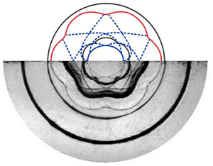
 $78\ \mathrm {\mu }\textrm {s}$). Detailed observations of the typical wave patterns and interfacial morphologies are shown in figure 4, where the coloured lines have been obtained by depicting the wave fronts and interfacial profiles in schlieren images via the Bessel curve function in CorelDraw software.

Figure 3. The evolution of  $\textrm {SF}_6$ layers with thicknesses of 35 mm (Case 1), 25 mm (Case 2) and 15 mm (Case 3) subjected to a cylindrical shock. Symbols are the same as those in figure 2.

Figure 4. Typical wave patterns (coloured lines) and interfacial morphologies (black lines) for Case 1. Symbols are the same as those in figure 2.
After the shock impingement, the amplitude of perturbation on the inner interface (heavy/light) decays quickly to nearly zero ( $38\ \mathrm {\mu }\textrm {s}$) (phase inversion), and then increases in the negative direction. Later, re-accelerated by the reflected shock RTS, the inner interface exhibits rapid instability growth. At late stages, finger-like bubbles and spikes arise due to the strong nonlinearity. Despite the rapid deformation of the inner interface, the outer interface presents a nearly perfect cylindrical shape at early stages (
 $t<138\ \mathrm {\mu }\textrm {s}$). Later, the distorted shock
  $\textrm {TS}_3$ passes through and also seeds a subtle perturbation on the outer interface. In Cases 1 and 2, this seeded perturbation suffers very slow growth for a long time (
 $t< 400\ \mathrm {\mu }\textrm {s}$), which indicates a negligible coupling effect between the inner and outer interfaces. We note that this behaviour is completely different from that of the outer perturbation case, where the initially-undisturbed inner interface deforms quickly from a very early time (Ding et al. Reference Ding, Li, Rui, Zhai and Luo2019). In Case 3, where the inner and outer interfaces are much closer together, the outer interface presents rapid instability growth at
  $407 \ \mathrm {\mu }\textrm {s}$. This is ascribed to the fact that, for Case 3, at late stages the quickly developing inner interface is very close to the outer interface and produces strong coupling effects. Note that for all three cases the ingoing rarefaction wave
  $\textrm {RW}_2$ interacts with the evolving inner interface, producing RT instability which further promotes the perturbation growth at the inner interface. A quantitative discussion of such instability promotion will be given later.
Variations of the overall perturbation amplitude of the inner interface with respect to time are plotted in figure 5(a). The error bar here refers to the pixel width in schlieren images, which blurs the interfaces and waves. In terms of the impingement moments of the typical waves  $\textrm {TS}_1$, RTS and
  $\textrm {RW}_2$, the instability growth at the inner interface can be divided into three stages. Impacted by the first transmitted shock
  $\textrm {TS}_1$, the perturbation amplitude first drops quickly to a smaller value due to shock compression, then decreases gradually to zero (
 ${\approx }50\ \mathrm {\mu }\textrm {s}$) and afterwards increases considerably on account of the induction of baroclinic vorticity (stage I). Later, re-accelerated by the outgoing shock RTS (reshock), the inner interface exhibits rapid perturbation growth that is quasi-linear in time (stage II). Note that the word ‘quasi-linear’ here means simply that the growth curve is almost linear; it does not refer to a precise mathematical property. Such quasi-linear growth is similar to previous results on planar RMI with reshock (Mikaelian Reference Mikaelian1989; Leinov et al. Reference Leinov, Malamud, Elbaz, Levin, Ben-Dor, Shvarts and Sadot2009). This can be explained by the fact that the present inner interface evolves at a nearly constant radial position after reshock (as indicated in the unperturbed case), and hence geometric convergence and the RT effect have negligible influence on the instability growth; i.e. the dominant regimes for the post-reshock growth of convergent RMI are nearly the same as those in the planar counterpart. More discussion of the post-reshock growth rate is presented later.

Figure 5. Temporal variations of (a) the overall perturbation amplitude and (b) the individual spike and bubble amplitudes of the inner interface for Cases 1–3. Symbols are the same as those in figure 2. The labels I, II and III stand for the three stages of the amplitude growth process for Case 2. For Case 1 or 3, the end of stage II should be shifted to the arrival time of  $\textrm {RW}_2$.
At stage III, the ingoing rarefaction wave  $\textrm {RW}_2$ collides with the inner interface, producing RT instability which further promotes the instability growth at the inner interface. In Case 1, in which the layer thickness is large, just before the interaction with
  $\textrm {RW}_2$ the inner interface has experienced long-term instability growth and thus presents a high perturbation amplitude. As a consequence, a strong RT instability is produced, which causes a noticeable promotion of the instability growth on the inner interface (
 $t>340\ \mathrm {\mu }\textrm {s}$). When the layer thickness is reduced to 25 mm (Case 2), the
  $\textrm {RW}_2$ interacts with the inner interface at an earlier time, which means that the interface experiences a shorter period of growth than in Case 1 and thus presents a smaller perturbation amplitude just before its interaction with
  $\textrm {RW}_2$. As a result, a moderately strong RT instability is produced, which prolongs the quasi-linear growth stage up to about
  $360\ \mathrm {\mu }\textrm {s}$. For the thinnest layer (Case 3), the inner interface presents a much smaller perturbation amplitude just before the arrival of
  $\textrm {RW}_2$, and thus the RT instability produced is the weakest among the three cases. Hence, despite the presence of RT instability, there is still a continuous reduction in perturbation growth rate in Case 3 (
 $t>240\ \mathrm {\mu }\textrm {s}$). This means that the RT effect in this case is too weak to stop the growth saturation. The present results suggest that one can modulate the late-stage instability growth at both the inner and outer interfaces by changing the layer thickness.
According to the previous studies of Mikaelian (Reference Mikaelian1995) and Jacobs et al. (Reference Jacobs, Jenkins, Klein and Benjamin1995), there exists a coupling effect between two adjacent interfaces evolving in a planar geometry. A recent study (Ding et al. Reference Ding, Li, Rui, Zhai and Luo2019) has demonstrated that such an interface coupling occurs also in the convergent setting. In the present work, a coupling angle originally proposed by Mikaelian (Reference Mikaelian1995) is employed to estimate the coupling strength between the inner and outer interfaces of the gas layers; this is written as
 \begin{equation} \sin\alpha=(2W_{1}/W_{2})/[1+(W_{1}/W_{2})^{2}], \end{equation}
 \begin{align} W_{1}/W_{2}&=1+\sinh(kd)\tanh(kd/2)\nonumber\\ &\quad +\sinh(kd)\frac{\rho_{1}}{\rho_{2}} \left\{1+\left[1+\left(\frac{\rho_{{2}}}{\rho_{1}}\right)^{2}+2 \left(\frac{\rho_{2}}{\rho_{1}}\right)\cosh(kd)\right]^{{1}/{2}}\right\}. \end{align}
Here,  $\alpha$ is the coupling angle, and k is the wavenumber, which equals
  $n/R$ for the perturbation in a cylindrical geometry. Based on equations (3.2) and (3.3), the coupling angles (
 $\alpha$) for Cases 1–3 are calculated to be 0.001, 0.011 and 0.077, respectively. For Cases 1 and 2, with relatively larger thicknesses, the coupling angles are smaller, which indicates weaker coupling effects. For Case 3, even though the value of
  $\alpha$ is relatively greater, the coupling effect is still too weak to affect the growth of each interface at early stages, as shown in figure 3. A good collapse of the perturbation growths at stages I and II for all three cases is found in figure 5, which demonstrates the negligible influence of interface coupling at early stages.
The growths of the individual bubble and spike amplitudes of the inner interface is plotted in figure 5(b). The bubble or spike amplitude is measured by taking the unperturbed interface trajectory as a reference. It is seen that the post-reshock spike growth (stage II) is far quicker than the post-reshock bubble growth in each case. A major reason is that spikes develop inwards (shown in figure 3) and their growth is promoted by geometric contraction, whereas bubbles develop outwards and their growth is inhibited by geometric expansion. At stage III, bubble growth is apparently accelerated by the rarefaction wave  $\textrm {RW}_2$ (particularly for Cases 2 and 3), whereas spike growth is not affected at all. At late stages, both spikes and bubbles saturate gradually and finally stop growing. This type of instability freeze-out has also been observed in the outer perturbation case (Ding et al. Reference Ding, Li, Rui, Zhai and Luo2019), and the physical mechanisms are given below. As the circumferentially distributed spikes (carrying heavy
  $\textrm {SF}_6$) move to the geometric centre at a high speed (
 ${\approx } 61\ \textrm {m}\,\textrm {s}^{-1}$), air in the vicinity of the geometric centre is continuously compressed and produces a drag force (i.e. an adverse pressure gradient) on the ingoing spikes. As this drag force is strong enough to balance the driving force of the growing spikes (i.e. induction of baroclinic vorticity), spikes stop developing. As indicated in the unperturbed case, the inner interface stays at a nearly fixed radial position after reshock, which means that air enclosed by the inner interface should obey volume conservation (i.e. have negligible compressibility). Hence, after spikes stop growing, the outward-moving bubbles have to slow down quickly to maintain a constant fluid volume. When both spikes and bubbles stagnate, the overall perturbation amplitude freezes out, as shown in figure 5(a). We claim that this type of instability freeze-out is a universal phenomenon for convergent RMI at a material interface close to the convergence centre. The above analysis shows that spike growth at late stages is dominated by geometric convergence, which reasonably explains the minor influence of the rarefaction wave on spike development.
3.3. $\textrm {SF}_6$ layers with different inner perturbations

To examine the influence of the initial perturbation on the instability growth, additional three layers with different amplitudes and wavelengths of perturbation on the inner interface are considered. The parameters corresponding to the initial conditions for these cases (Cases 4–6) are listed in table 1. Sequences of schlieren images illustrating the developments of the waves and the interfaces are shown in figure 6. The overall instability evolution processes are similar to those of Cases 1–3 and thus are not detailed here. It is also observed that the small perturbation on the outer interface seeded by the distorted shock  $\textrm {TS}_3$ experiences very slow growth for a long time. This is different from the outer perturbation case (Ding et al. Reference Ding, Li, Rui, Zhai and Luo2019), where the seeded perturbation on the initially uniform interface grows considerably from a very early time. Such slow instability growth may be ascribed to the following factors. Firstly, the interaction between the
  $\textrm {TS}_3$ and the outer interface is an instance of the non-standard RMI (Ishizaki et al. Reference Ishizaki, Nishihara, Sakagami and Ueshima1996), in which a distorted shock interacts with a uniform interface. As reported by Zhai et al. (Reference Zhai, Liang, Liu, Ding, Luo and Zou2018a) and Zou et al. (Reference Zou, Al-Marouf, Cheng, Samtaney, Ding and Luo2019), the driving mechanisms of such a non-standard RMI are different from those of its standard counterpart (in which a uniform shock impacts a distorted interface), and the instability growth is much slower than for the latter. Secondly, due to geometric expansion, the instability growth induced by a diverging shock
  $\textrm {TS}_3$ is inherently slower than that of the planar or convergent setting. Thirdly, using equations (3.2) and (3.3), the coupling angles for Cases 4–6 are calculated to be 0.011, 0.011 and 0.0004, respectively, which indicates weak coupling effects at early stages; i.e. the deformation of the inner interface produces a negligible influence on the outer interface.

Figure 6. The evolution of  $\textrm {SF}_6$ layers with different initial amplitudes and azimuthal mode numbers for the inner interface:
  ${a}_0 = 1\ \textrm {mm}$,
  ${n} = 6$ (Case 4);
  ${a}_0 = 2\ \textrm {mm}$,
  ${n} = 6$ (Case 5); and
  ${a}_0 = 2\ \textrm {mm}$,
  ${n} = 10$ (Case 6). Symbols are the same as those in figure 2.
At late stages ( $t> 400\ \mathrm {\mu }\textrm {s}$), the inner interface presents a large perturbation and its crest is very close to the outer interface. As a result, the layer thickness becomes very small, producing strong coupling effects. Therefore, the outer interface distorts quickly and persistently from then on. In particular, for Case 5, the quickly developing inner interface approaches the outer interface, causing rapid deformation of the outer interface (
 $426\ \mathrm {\mu }\textrm {s}$). For Case 6, even though the value of coupling angle is small, the outer interface distorts at late stages due to the increased coupling effect (
 $440\ \mathrm {\mu }\textrm {s}$). It is also observed that the perturbation wavenumber at the outer interface is closely related to the initial perturbation wavenumber of the inner interface. The present results suggest that the coupling effect between the two interfaces plays an important role in the instability development at late stages.
Temporal variations of the overall perturbation amplitude of the inner interface for Cases 2, 4, 5 and 6 are plotted in figure 7(a). Following the impact of  $\textrm {TS}_1$, the perturbation amplitude decreases gradually to zero (phase reversal) and then increases continuously. After the reshock (i.e. the passage of the reflected transmitted shock RTS), the perturbation amplitude experiences a long period of growth that is quasi-linear in time. Figure 7(b) shows the growths of the individual bubble and spike amplitudes. It is seen that the bubble growth shows a weak dependence on the initial perturbation amplitude and wavelength, whereas the spike growth shows a strong dependence. In particular, the interface with a larger initial amplitude-to-wavelength ratio presents a higher saturation spike amplitude at late stages. The reason is given below. The spike dynamics at late stages is dominated by two mechanisms. One is the driving force produced by baroclinic vorticity, whose strength is positively correlated with the initial amplitude-to-wavelength ratio. The other is the drag force caused by geometric convergence, which is independent of the initial perturbation. For cases with a larger initial amplitude-to-wavelength ratio, stronger baroclinic vorticity is deposited on the interface, which produces a greater driving force acting on the growing spike. As a consequence, the spike amplitude can grow to a higher saturation value than in the case of a small amplitude-to-wavelength ratio. It is also found that the rarefaction wave
  $\textrm {RW}_2$ promotes bubble growth but has a negligible influence on spike growth.

Figure 7. Temporal variations of (a) the overall perturbation amplitude and (b) the individual spike and bubble amplitudes of the inner interface for Cases 2, 4, 5 and 6. Symbols are the same as those in figure 2. The labels I, II and III stand for the three stages of the amplitude growth process.
The current work provides very scarce experimental results on the convergent RMI under reshock at a two-dimensional single-mode interface. The RMI with reshock or multiple shocks exists widely in reality, and thus has attracted continuous attention in recent years. Due to the high complexity of this problem, only two types of empirical models have been developed to estimate the post-reshock perturbation growth (Mikaelian Reference Mikaelian1989; Charakhch'an Reference Charakhch'an2000; Leinov et al. Reference Leinov, Malamud, Elbaz, Levin, Ben-Dor, Shvarts and Sadot2009). One reshock model, applicable to interfaces with initial three-dimensional multi-mode perturbations, was proposed by Mikaelian (Reference Mikaelian1989); it is written as
 \begin{equation} \frac{\textrm{d}h_\textrm{2}}{\textrm{d}t}=C\Delta V_{2}A_2^{+}. \end{equation}
Here,  $h_2$ is the overall width of the mixing zone; for the present experiments it represents the distance between the spike and bubble tips. The quantity
  $\textrm {d}h_{2}/\textrm {d}t$ is the perturbation growth rate after reshock,
  $\Delta V_{2}$ is the velocity jump caused by reshock,
  $A_2^{+}$ is the post-reshock Atwood number and
  $C=0.28$ is an empirical constant. In later work, the empirical constant
  $C$ was found to be dependent on the perturbation randomness and the domain dimension at the time of reshock (Leinov et al. Reference Leinov, Malamud, Elbaz, Levin, Ben-Dor, Shvarts and Sadot2009; Ukai, Balakrishnan & Menon Reference Ukai, Balakrishnan and Menon2011). Equation (3.4) indicates that the pre-reshock growth rate has a negligible influence on the post-reshock one. Another empirical model, suitable for initial two-dimensional single-mode interfaces, was proposed by Charakhch'an (Reference Charakhch'an2000); it can be written as
 \begin{equation} \frac{\textrm{d}h_{2}}{\textrm{d}t}=\beta\Delta V_{2}A_2^{+}-\frac{\textrm{d}h_{1}}{\textrm{d}t}, \end{equation}
where  $\textrm {d}h_{1}/\textrm {d}t$ is the growth rate just before reshock, and the empirical coefficient
  $\beta$ is found to be 1.25 by fitting a large number of numerical results. So far, the value of
  $\beta$ has never been verified by experiments, since there is a substantial lack of experimental data on reshocked RMI at a well-defined two-dimensional single-mode interface.
The above models imply that, for planar RMI under reshock, the post-reshock growth rate is almost independent of the pre-reshock amplitude and wavelength. So far, the dynamics of convergent RMI under reshock has seldom been studied, and the post-reshock growth behaviour remains unknown. The present results on the instability growth at the inner interface provide a rare opportunity to examine the growth behaviour of convergent RMI under reshock at a two-dimensional single-mode interface. The post-reshock growth rate can be obtained by a linear fitting of the experimental data at stage II for each case, as listed in table 2. It is found that the post-reshock growth rate is closely related to the pre-reshock one, which depends on the initial perturbation amplitude and wavelength. This is in accordance with our observations in figures 3 and 6 that the evolving interface maintains a sharp morphology at the time of reshock. As suggested by Charakhch'an (Reference Charakhch'an2000) and Ukai et al. (Reference Ukai, Balakrishnan and Menon2011), for a sharp interface at the reshock, the pre-reshock growth rate could significantly affect the post-reshock instability growth.
Table 2. The post-reshock growth rates from the present experiments, the experiments of Biamino et al. (Reference Biamino, Jourdan, Mariani, Houas, Vandenboomgaerde and Souffland2015) and the theoretical predictions from (3.6) (last column). The quantities  $\textrm {d}h_1/\textrm {d}t$ and
  $\textrm {d}h_2/\textrm {d}t$ are respectively the pre-reshock and post-reshock perturbation growth rates,
  $\Delta V_{2}$ is the velocity jump caused by reshock,
  $A_2^{+}$ is the post-reshock Atwood number and
  $b$ is the empirical coefficient in (3.6).

Given these findings, and also assuming that the post-reshock growth rate of the convergent RMI is independent of the pre-reshock amplitude and wavelength, here we propose the following empirical model for the convergent RMI with reshock at an initial two-dimensional single-mode interface (heavy/light):
 \begin{equation} \frac{\textrm{d}h_{2}}{\textrm{d}t}=b\Delta V_{2}A_2^{+}+\frac{\textrm{d}h_{1}}{\textrm{d}t}. \end{equation}
Note that no geometric parameters exist in (3.6), since, as stated before, geometric convergence/divergence has negligible influence on the instability growth after reshock. It is expected that a constant empirical coefficient  $b$ can be found for cases with different initial conditions, such that the above assumption and the model can be validated. From the measured growth rates before and after the reshock, the empirical coefficient
  $b$ for each case is obtained; the results are listed in table 2. It is found that for Cases 1–6, with different pre-reshock amplitudes and wavelengths,
  $b$ varies in a small range, which supports our assumption. From the calculated coefficients for different cases, an averaged value of
  $b=0.73$ is obtained. It is shown in table 2 that the new empirical model with
  $b=0.73$ gives a reasonable prediction of the post-reshock growth rate for all cases considered in this work. Table 2 also provides a comparison of the model's predictions against the experimental results of Biamino et al. (Reference Biamino, Jourdan, Mariani, Houas, Vandenboomgaerde and Souffland2015), which further demonstrates the model's accuracy. The present empirical model is useful for estimating the post-reshock instability growth of convergent RMI.
It should be stressed that the present empirical model is different from that of Charakhch'an (Reference Charakhch'an2000). The model of Charakhch'an (Reference Charakhch'an2000) is applicable to the reshocked RMI at a light/heavy interface. For this case, the direction of baroclinic vorticity deposited on the interface during the reshock is opposite to that of baroclinic vorticity produced by the incident shock. This means that the incident and reflected shocks have opposite effects on the post-reshock perturbation growth, which is reflected by the different signs of the two terms on the right-hand side of (3.5). By contrast, in the present experiments, the inner interface of the gas layer is of a heavy/light configuration. For this case, the incident and reflected shocks produce baroclinic vorticity in the same direction, and thus the two terms on the right-hand side of (3.6) possess the same sign. As has been recognized by the RMI community, the instability evolution processes for the light/heavy and heavy/light configurations are distinctly different. This is a possible reason for the different values of coefficient in the two models.
4. Conclusion
In this work, the RMI at a perturbed gas layer with a uniform outer surface and a sinusoidal inner surface accelerated by a cylindrical shock has been examined using shock-tube experiments. With a novel soap film technique, the layer thickness and the boundary shapes can be well controlled. Dynamic evolution of the wave patterns and the interfacial morphologies is captured by high-speed schlieren photography. The influences of the layer thickness and the initial perturbation of the inner interface on the instability growth are highlighted.
After the shock impact, the initially uniform outer interface suffers only a slight deformation over a long period. Nevertheless, it distorts quickly at late stages, when the quickly developing inner interface is very close to it and produces strong coupling effects, especially in cases with a larger amplitude-to-wavelength ratio and a smaller thickness. The instability growth on the inner interface is divided into three stages. At stage I, the perturbation amplitude first drops suddenly to a smaller value due to shock compression, then decreases gradually to zero (phase reversal) and afterwards increases sustainedly in the negative direction. After the reshock, the perturbation undergoes a long period of growth that is quasi-linear in time (stage II). The quasi-linear growth rate is found to be a weak function of the pre-reshock amplitude and wavelength, but depends evidently on the pre-reshock growth rate. A new empirical model for the growth of convergent RMI under reshock is proposed, which reasonably predicts the present experimental results and those of Biamino et al. (Reference Biamino, Jourdan, Mariani, Houas, Vandenboomgaerde and Souffland2015). At stage III, a rarefaction wave reflected from the outer interface interacts with the deforming inner interface, producing the RT instability, which further promotes the perturbation growth at the inner interface.
The RT effect and the interface coupling, which dominate the late-stage developments of the inner and outer interfaces, respectively, depend heavily on the layer thickness. Therefore, controlling the layer thickness is an effective way to modulate the late-stage instability growth. Specifically, the thicker the gas layer, the slower the development of the outer interface, and the quicker the development of the inner interface. The present results are different from those in the outer perturbation case (Ding et al. Reference Ding, Li, Rui, Zhai and Luo2019), where the layer thickness affects the instability growth from a very early time. This work is an important step towards a complete understanding of hydrodynamic instabilities at a perturbed layer, and the findings may be useful for the target design.
Acknowledgements
This work was supported by the National Natural Science Foundation of China (nos 11802304, 11625211, 11621202 and 11722222), the Science Challenge Project (no. TZ2016001), the Strategic Priority Research Program of the Chinese Academy of Sciences (no. XDB22020200) and the CAS Centre for Excellence in Complex System Mechanics.
Declaration of interests
The authors report no conflict of interest.


