Introduction
Nowadays, microwave-based systems are becoming more and more available to end-consumers. One of the most representative example is the integration of radar systems into vehicles for safety improvement and the upcoming autonomous driving capability. With the increasing market volume, the demand for a rising degree of automation in industrial fabrication is necessary, also covering end-of-line tests. The latter is not interesting for quality management purpose only, but especially for fast and reliable calibration of each single product. Even if identical parts are used, the sum of component tolerances potentially leads to performance deviations for every radar system leaving the production site. Especially for the given example in the automotive sector, where high safety standards have to be met, it is crucial, that every module operates within its specifications. Thus the calibration of each individual system and consequently detection of faulty devices is desired. To fully test a radar module to its maximum operable distances up to several hundred meters, an excessively large and expensive anechoic chamber would be required. To avoid this, a method to generate artificial targets at arbitrary distances in a limited-sized but well-defined indoor environment is necessary. Many existing simulator systems have mainly been developed for research purpose with focus on the signal-processing chain. They are either realized completely in software [Reference Dahl, Rolfes and Vogt1,Reference Scheiblhofer, Treml, Schuster, Feger and Stelzer2] or utilize FPGAs to emulate the radar system itself within a specific target scenario [Reference Tai, Chao and Naichang3,Reference Ergezer, Keskin and Gunay4]. Concepts for the implementation of simulators, designed to generate artificial targets for a real radar system in the radio frequency (RF) domain as hardware-in-the-loop approach have been presented in [Reference Lutz, Erhart, Walte and Weigel5,Reference Engelhardt, Pfeiffer and Biebl6] and commercially available systems can be found by e.g. Keysight with the E8707A [7] or Rohde & Schwarz with the ARTS9510. There, the signal impinging at the simulator is downconverted and altered according to the desired target parameters in the analog or digital domain by usage of phase-shifters, coaxial, or optical delay lines as well as attenuators and amplifiers. After upconversion, the resulting modified replica of the received signal is retransmitted to the radar system under test. Besides high expenses of the necessary components, a major drawback is that often only up to two artificial targets can be generated. As stated in [Reference Groschel, Zarei, Carlowitz, Lipka, Sippel, Ali, Weigel, Schober and Vossiek8], the necessity of reliable and precise calibration is also a dominant topic in the domain of mobile communication, especially for the upcoming 5G technology with MIMO transceiver arrays. Because of the necessary amount of hardware, the mentioned solutions consists of bulky and thus less mobile equipment combinations. Hence a possibility to enable an angle-of-arrival (AoA) evaluation can be done by mounting the radar system under test on a rotatable platform. Nevertheless the capability to simultaneously generate multiple targets under different angles is limited without a full simulator setup for each target. In the present work, a novel concept for the realization of an frequency-modulated continuous-wave (FMCW) radar target simulator (RTS) is presented, capable to generate multiple independent targets at user-selectable distances, and with different radar cross-section (RCS), velocities, and especially angles relative to the radar system to close this gap. Because of the capability of the system to simultaneously generate multiple targets at different angles, it is a valuable addition to the existing target simulators with focus on a cost-efficient implementation of high-volume end-of-line calibration procedure of different radar modules. While the concept does not directly influence the round-trip delay-time (RTDT) τ it is nevertheless capable to fulfill the main requirements for this tasks. This contribution is an extended version of [Reference Scheiblhofer, Feger, Haderer and Stelzer9]. Compared with this, additional realizations of the developed hardware for the RTS are presented and a novel mode of operation is introduced. This mode vastly increases the overall dynamic range of the selectable RCS from 20 to 50 dB. Therefore the demand for proper generation of distant targets as well as close targets with low RCS can be met. In addition, methods to increase the number of simultaneously producible virtual targets are shown and a more in-depth characterization of the necessary hardware components is presented.
Simulator basics
The presented RTS is based on the measurement approach of the modulated-reflector radar (MRR) [Reference Miesen, Ebelt, Kirsch, Schafer, Li, Wang and Vossiek10]. The underlying concept is an extension of the conventional FMCW radar system, using linear frequency-sweeps to determine the distance to objects in the path of the transmitted electromagnetic wave [Reference Stove11]. The MRR is designed to estimate the distance to multiple modulated-reflector nodes (MRN), which are mounted on the objects of interest. These objects then can easily be located and tracked by the MRR. The principle of operation can be described by the schematic in Fig. 1. The radar frontend (FE) transmits a frequency chirp  $s_{{\rm TX}}$, which impinges at the reflector after half of the RTDT τ. For simplicity and to cover the possible modulation methods the core of the reflector is modeled as ideal mixer, multiplying the incoming signal with its own modulation signal
  $s_{{\rm mod}}$ and retransmits the result back to the FE. This modulation signal itself is modeled using the magnitude
  $A_{{\rm mod}}$, frequency
  $f_{{\rm mod}}$, and initial phase
  $\varphi _{0,{\rm mod}}$. The received signal
  $s_{{\rm RX}}$ is down converted with
  $s_{{\rm LO}}$, filtered to remove aliases, amplified, sampled, and fed to the base band stage for subsequent signal processing. The detailed derivation of the signal model can be found in [Reference Scheiblhofer, Feger, Haderer and Stelzer9]. The resulting intermediate frequency (IF) signal
  $s_{{\rm MRR}}$ consists of two dominant spectral components
 $$\eqalign{ s_{{\rm MRR},m}^ + \left( t \right) & = A{\rm cos }(2\pi \left( {k_{{\rm sw}}\tau + f_{{\rm mod}}} \right)t + \cr & \quad + 2\pi f_{\rm 0}\tau + \varphi _{0, {\rm r}} + \varphi _{0,{\rm mod}} + \varphi _{\xi ,m}),} $$
 $$\eqalign{ s_{{\rm MRR},m}^ - \left( t \right) & = A{\rm cos}\left( {2\pi \left( { - k_{{\rm sw}}\tau + f_{{\rm mod}}} \right)t - } \right. \cr & \quad \left. { - 2\pi f_{\rm 0}\tau - \varphi _{0, {\rm r}} + \varphi _{0,{\rm mod}} - \varphi _{\xi ,m}} \right)} $$
where the magnitude is defined by  $A=A_{{\rm TX}}^{2}\delta _{{{ {\rm r}}}}/4$. Here,
  $A_{{\rm TX}}$ is the transmit (TX) power of the originally transmitted signal from the basestation and
  $\delta _{{{ {\rm r}}}}$ the damping factor caused by the RCS
  $\sigma _{{{ {\rm r}}}}$ of the MRN and the free-space loss due to the distance R. The magnitude of the modulation signal
  $A_{{\rm mod}}$ is also included in
  $\delta _{{{ {\rm r}}}}$, as well as the gain of the downconversion mixer and the used IF amplifiers. The constant phase shift
  $\varphi _{0,{{{\rm r}}}}$ is caused by the mechanical setup of the unmodulated MRN with
  $\varphi _{0,{\rm mod}}=0$ and thus is similar to the phase shift
  $\varphi _{0}$ of a passive target. Further used parameters are the ramp-slope
  $k_{{\rm sw}}=B_{{\rm sw}}/T_{{\rm sw}}$, that is calculated with the bandwidth
  $B_{{\rm sw}}$ as difference between start- and stop frequency of the chirps
  $f_{0}$ and
  $f_{1}$, respectively, and the ramp-duration
  $T_{{\rm sw}}$. Under the assumption of a multi-channel FE with
  $m=1\ldots M$ receive (RX) channels, the value
  $\varphi _{\xi ,m}$ is used to describe the phase offset of each channel to a reference channel. In Fig. 2, an exemplary spectrum of the MRR signals of a single RX channel is depicted. Here, the spectral components caused by two MRNs, separated by different modulation frequencies
  $f_{{\rm mod},1}$ and
  $f_{{\rm mod},2}$ and at different distances to the radar base station proportional to the RTDTs
  $\tau _{1}$ and
  $\tau _{2}$ are shown. The frequency components from (2.1) with
  $f_{{\rm MRR},i}^{+} = k_{{\rm sw}}\tau _{i}+f_{{\rm mod},i}$ and (2.2) with
  $f_{{\rm MRR,}i}^{-} = -k_{{\rm sw}}\tau _{i}+f_{{\rm mod},i}$ are centered at the modulation frequency
  $f_{{\rm mod},i}$, where
  $i=1\ldots 2$ is used as index for the corresponding MRN

Fig. 1. Schematic representation of the modulated reflector radar. On the left, a 24 GHz frontend of the radar module is sketched, where components in the gray box are in the focus of conducted calibration measurements. On the right, a modulated reflector node is depicted.

Fig. 2. Spectral domain representation of the MRR caused by two MRNs with different modulation frequencies and different distances.
As the purpose of the RTS system presented in this paper, is to simulate arbitrary targets with well defined properties, it is necessary to compare interesting parameters from the MRR and a conventional FMCW radar system. The IF signal of the latter one can be written as
 $$s_{{\rm conv},m}\left( t \right) = {\rm }\displaystyle{{A_{{\rm TX}}^2 } \over 2}\delta {\rm cos}\left( {2\pi k_{{\rm sw}}\tau t + 2\pi f_0\tau + \varphi _0 + \varphi _{\xi ,m}} \right)$$
with δ as damping factor and  $\varphi _{0}$ as phase shift caused by the passive targets. For simplicity we focus on
  $s_{{\rm MRR}}^{+}(t)$ and use (1) for the comparison. The findings, separated into terms of frequency, phase, and magnitude, are summarized in Table 1.
Table 1. Comparison of signal components
MRN design and characterization
Before it is described how artificial targets are generated, a brief overview of the design and operational principle of the MRN is given.
MRN basics
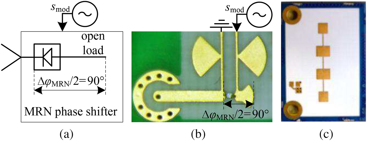
A basic concept of the MRN hardware is that the modulation signal can be generated by a rectangular sequence with modulation frequency  $f_{{\rm mod}}$. Thus, the core component of the reflector node is a switch, realized by a low-cost PIN-diode, as depicted in Fig. 3. The PIN-diode is used as active element in a reflective phase shifter. In its on-state, the RF power can pass the diode and is reflected at the end of a mushroom-shaped stub, whereas in the off-state the point of reflection is at the diode's cathode. Due to the defined stub-length of
  ${\lambda }/{4}$ with λ as the wavelength of the electromagnetic wave at the center frequency
  $f_{{\rm c}}=24.125\,{\rm GHz}$, a phase shift of
  $\triangle \varphi _{{\rm MRN}}=180^{{\rm o}}$ can be realized. Although the modulation is reduced to a pure phase-modulation scheme, the signal model in the Section “Simulator basics” is still valid, because of its representation as analytical signal. Thus, the phase modulation can be converted into the amplitude-like modulation resulting in the given signal model. The behavior of the phase shifter concerning the gain
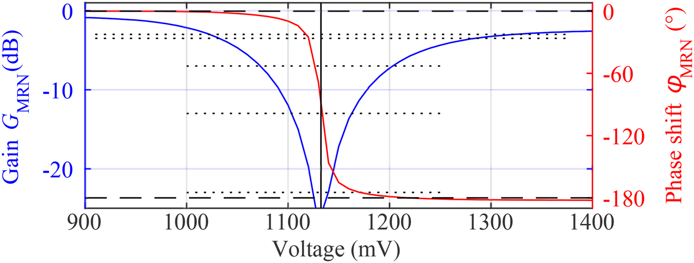
  $G_{{\rm MRN}}$ and phase
  $\varphi _{{\rm MRN}}$ over the applied voltage has been characterized with a network analyzer and is depicted in Fig. 4. The switching threshold between on- and off states is 1130 mV. Note that there is a gain-deviation between on- and off states. Therefore it is preferable to select switching voltages at points of equal magnitudes to avoid additional amplitude-modulation effects. Furthermore, the transition region can be used to actively adjust the attenuation of the reflector in the simulator setup, while nearly maintaining the desired phase shift of
  $\triangle \varphi _{{\rm MRN}}=180^{{\rm o}}$. A more detailed characterization of the frequency behavior is depicted in the Smith-chart given in Fig. 5. In blue, the course of the reflection coefficient within the 24 GHz band, ranging from
  $f_{0}=24\, {\rm GHz}$ to
  $f{}_{1}=24.25\, {\rm GHz}$ by variation of the applied voltage at the diode can be seen. The colored lines are examples of the behavior at fixed voltages over frequency.

Fig. 3. The core component of the MRN is a reflective phase shifter, realized with a single PIN-diode, depicted in (a) and (b). In (c) the front side of a reflector with one possible antenna configuration is shown.

Fig. 4. Magnitude (blue) and phase (red) of the gain of the reflective phase shifter by variation of the voltage, applied to the diode at  $f_{{\rm c}}=24.125\, {\rm GHz}$.
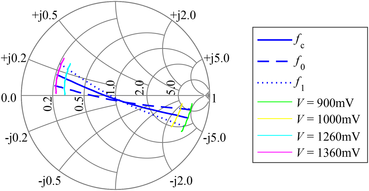
Fig. 5. The Smith-chart shows selected courses of the reflection coefficient of the reflective phase shifter by variation of the applied voltage and frequency.
Enhanced MRN
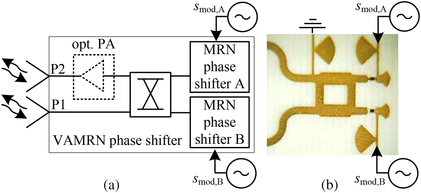
Besides the single-antenna reflector, as depicted in Fig. 3, a multi-antenna reflector using two of these switching-cores can be assembled. The setup of this reflector core is depicted in Fig. 6. By using an additional 3-dB  $90^{{\rm o}}$-hybrid coupler, a bidirectional phase-shifting circuitry is realized as it can be found in [Reference Pozar12]. In normal operation mode, the two phase shifters are modulated with the same signal
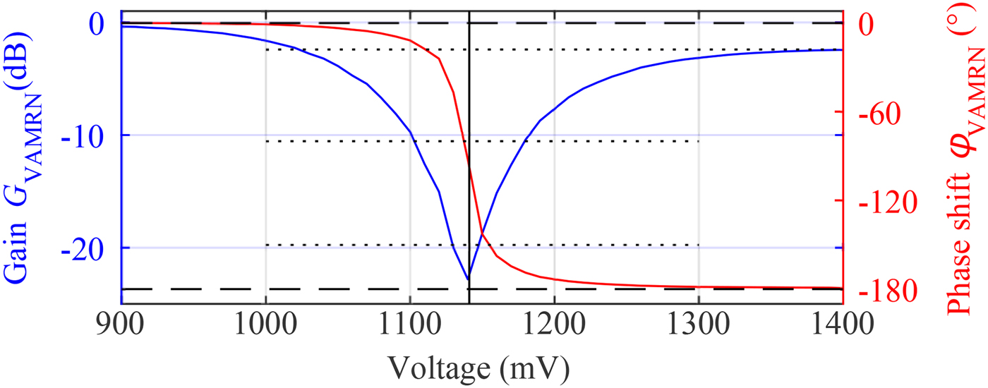
  $s_{{\rm mod,A}}=s_{{\rm mod,B}}=s_{{\rm mod}}$. This enhanced switching-core is additionally combined with a retro-directive Van Atta antenna array [Reference Sharp and Diab13] as it is also used in [Reference Fink, Kennedy and Lin14] to extend the readout range of passive SAW tags. While this Van Atta MRN (VAMRN) works identical to the single-antenna MRN, it retransmits the received and modulated signal into the initial direction of arrival. Thus, its major advantages are given by an improved multipath suppression and increased operable range. The results of the performed measurements for the characterization of the VAMRN switching-core are depicted in Figs 7 and 8. In contrast to the characterization of the single MRN, the gain is determined by the insertion gain represented by the relation of the input power at port P1 and the corresponding output power at the second port P2. Several applications require the usage of semi-passive reflector tag systems, that are constructed with the focus of a low-power consumption and thus can be powered from battery. In other applications, this is a less important requirement, and thus active reflector nodes can be used. This kind of reflector does not only retransmit the modulated impinging signal back to the sender, but it is also capable to amplify the signal, resulting in higher operable ranges. Especially in scenarios where some of the MRNs are operating as static anchor points within the area of interest and thus are placed at fixed locations, it is suitable that these tags are connected to a central power supply. The design of the VAMRN can easily be modified by inserting an optional power amplifier (PA), as it is indicated in Fig. 6.

Fig. 6. The schematic setup of the VAMRN, using two MRN phase shifters is depicted in (a). In (b) a photography of the realized hardware with the connections to the antennas on the left side is shown.

Fig. 7. Magnitude (blue) and phase (red) of the gain of the VAMRN phase-shifting core, determined at  $f_{{\rm c}}$.

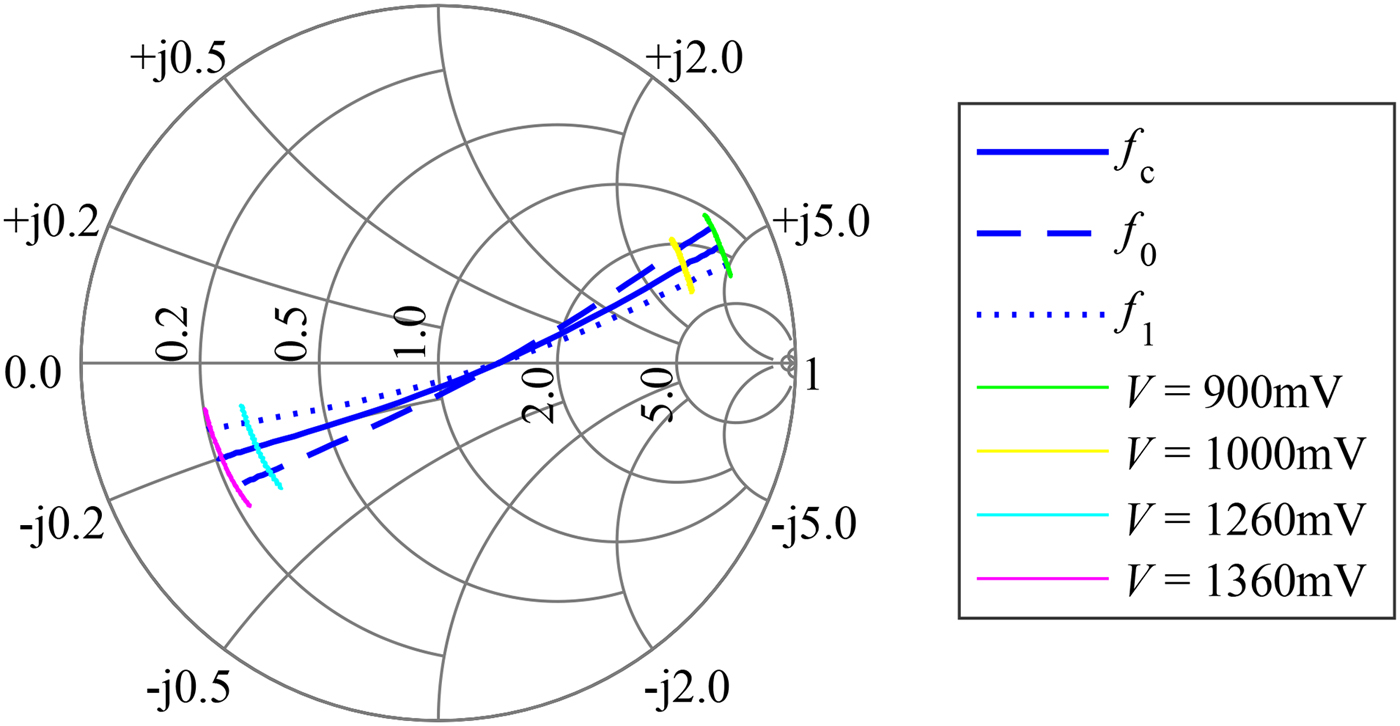
Fig. 8. The Smith-chart of the VAMRN shows similar courses of the reflection coefficient compared with the single-MRN core.
Target generation
In the following, it is discussed how a MRN can be used to simulate a radar target defined by the parameters of the conventional FMCW radar in Table 1. In general, the characterization of a radar system as device under test (DUT) is performed in specially prepared anechoic chambers. Thus, it can be assumed, that the true location of the static MRNs relative to the DUT, and thus τ is well-known.
Distance
The term  $k_{{\rm sw}}\tau $ in (1) denotes the base band frequency corresponding to the true distance between the radar FE and a target or MRN, respectively. As it can be seen, the IF frequency is shifted due to
  $f_{{\rm mod}}$, thus a virtual target at the RTDT
  $\tau _{{\rm sim}}$ can be generated by setting
 $$f_{{\rm mod}} = {\rm }k_{{\rm sw}}\left( {\tau _{{\rm sim}} - \tau } \right).$$
As discussed in the Section “Simulator basics”, a second target occurs for every MRN. As this characteristic of the system is known and the position of this second target can also be calculated it is possible to ignore this part of the signal.
Radar cross section
Another parameter, that can be influenced, is the simulated RCS σ, relating the incident and reflected power at an object. For the RTS system in this work, the reflected power directly depends on the gain of the antennas  $G_{{\rm ant,{r}}}$ and the attenuation
  $G_{{{{\rm r}}}}$ of the MRN, see Fig. 4. As the same antenna is used for reception and transmission of the incident signal,
  $G_{{\rm ant,{r}}}$ has to be taken into account twice. Referring to [Reference Hoogeboom, Elferink and Trampuz15], the RCS of such a reflector can be calculated with
  $\sigma _r = G_{{\rm ant},{\rm r}}^2 G_{{\rm MRN}}\displaystyle{{\lambda ^2} \over {4\pi }}$. The reference value of the RCS is defined by the antenna gain. Furthermore, it can be tuned electronically by altering the attenuation
  $G_{{\rm MRN}}$. Referring to the findings given in Figs 4 and 7, this can be accomplished by proper selection of the MRN modulation signal's on- and off voltages, resulting in a dynamic range of the RCS of about
  $20\, {\rm dB}$. However, the figures also state that an accurate RCS setting can be a demanding task for high attenuation values in the regions close to the on–off threshold level. Thus an additional approach applicable to the VAMRN modules is presented in the following, taking advantage of the two switching circuits. In normal operation, these phase-shifting circuits are controlled using identical modulation signals, originating from a single source, and thus giving identical switching behavior according to the magnitude, frequency, and phase. In general, these phase shifters can be driven by independent signals. In the present case, two modulation signals with identical frequency and magnitude but with an additional phase offset
  $\Delta \varphi _{{\rm 0,VAMRN}}=\varphi _{{\rm 0,mod,B}}-\varphi _{ {\rm 0,mod,A}}$ are generated. The VAMRN can be modeled as the superposition of two MRNs at the same location, and thus the signal model of (1), only has to be modified slightly, leading to
 $$\eqalign{ s_{{\rm VAMRN}}^ + \left( t \right) & = \displaystyle{A \over 2}{\rm cos}\left( {2\pi f_{{\rm MRR}}t + \varphi _{{\rm MRR}}} \right) \cr & \quad + \displaystyle{A \over 2}{\rm cos}\left( {2\pi f_{{\rm MRR}}t} \right. \cr & \quad \left. { + \varphi _{{\rm MRR}} + \Delta \varphi _{{\rm 0},{\rm VAMRN}}} \right).} $$
Here, the substitutions  $f_{{\rm MRR}}=k_{{\rm sw}}\tau +f_{{\rm mod}}$ and
  $\varphi _{{\rm MRR}}=2\pi f_{{\rm 0}}\tau + \varphi _{0, {{{\rm r}}}}+\varphi _{0, {\rm mod}}$ have been used and the angle-dependent value m has been ignored. The prerequisite, that the signal magnitudes are splitted equally among both single phase shifters is fulfilled by the symmetric design of the reflector node. For simplicity we focus on
  $s_{{\rm VAMRN}}^{+}(t)$ only, the result for
  $s_{{\rm VAMRN}}^{-}(t)$ can be derived in the same way. Using trigonometric identities for the superposition of cosine-terms to transform the phase shift to a scaling of the signal amplitude [Reference Jeffrey and Dai16], equation (5) can be represented by a single cosine as
 $$\eqalign{ s_{{\rm VAMRN}}^ + \left( t \right) & = \sqrt {{\displaystyle{A \over 2}}^2\left[ {1 + {\rm cos}\left( {\Delta \varphi _{{\rm 0},{\rm VAMRN}}} \right)} \right]} \cr & \quad {\rm cos}\left( {2\pi f_{{\rm MRR}}t + \varphi _{{\rm 0},{\rm VAMRN}}} \right),} $$
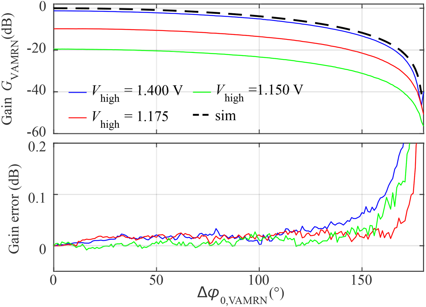
where constant phase terms are summarized by  $\varphi _{{\rm 0,VAMRN}}$. In Fig. 9, the slope of a simulated attenuation with a reference level at
  $0\, {\rm dB}$ is compared with measurement results. The coarse attenuation is defined by the selected on- and off voltages, marked by the dotted lines in Fig. 7. As expected, the attenuation rises with increasing phase difference due to the destructive overlapping of the phase shifted cosines. In the bottom of the same figure, the difference between the theoretical and measured gain-values is depicted. The outcome states the capability to precisely set the reflected power, and thus the desired RCS of the artificial target by setting the phase difference
  $\Delta \varphi _{ {\rm 0,VAMRN}}$ between the two participating switching-cores of the VAMRN. Additionally, this approach vastly increases the effective dynamic range of the reflected power up to 50 dB, and thus enables the simulator system to either precisely generate targets at long ranges and close targets with small RCS.

Fig. 9. The top figure shows different measured slopes for the attenuation approach taking advantage of the VAMRNs dual phase-shifting circuity. In the bottom, the difference between the simulated and measured slopes is depicted stating only minimal error values over a wide range.
Phase/velocity
To set the phase of the artificial targets a possibility to set  $\varphi _{0}=\varphi _{0, {{{\rm r}}}}+\varphi _{0, {\rm mod}}$ is necessary. While
  $\varphi _{0, {{{\rm r}}}}$ is constant due to the mechanical setup of the MRN the variable
  $\varphi _{0, {\rm mod}}$ has to be set accordingly. This is feasible, when the start of the modulation can be synchronized with the start of the ramp of the DUT, but in general this option is not available. However, the concept is capable to simulate a dynamic scenario necessary for range Doppler (RD) evaluations, where the phase response over
  $N_{ {\rm sweeps}}$ consecutive FMCW-chirps is used to extract the velocity information. The necessary phase shift
  $\Delta \varphi _{0, {\rm mod}}=\varphi _{0, {\rm mod,}n}-\varphi _{0, {\rm mod},n-1}$ between the chirps can be generated by appropriate selection of the modulation frequency
  $f_{{\rm mod}}$ in dependency of the sweep cycle's period
  $T_{{{\rm p}}}$ as it can be seen in Fig. 10 and can be set by
 $$f_{{\rm mod}} = {\rm }v_{{\rm doppler}}\displaystyle{{2f_0} \over {c_0}}.$$
While, in general, the simulated target range and velocity can be set independently, the entanglement of (4) and (7), gives the opportunity to define a set of combined distance-velocity combinations depending on the ramp parameters.

Fig. 10. RD interrogation sweep sequence with corresponding phase of modulation signal.
Angle-of-arrival
As another feature, the MRR is capable of performing AoA signal processing by evaluating the phase differences of the impinging wave at the receive channels. To achieve precise angular estimates, it is necessary to determine the initial phase offsets  $\varphi _{{\rm \alpha }}$, caused by different electrical lengths of the on-board RF lines for each multi-channel FE. The fact that every MRN generates two peaks in the spectrum gives the capability to obtain this offset twice for each calibration measurement, from (1) and (2).
Multi-target generation
Until now it has been derived, how a single reflector node can be used to generate artificial targets depending on the modulation frequency  $f_{{\rm mod}}$ and the true distance between the radar system and the node. It has to be noted that it is also possible to generate multiple targets using a single MRN. This is especially interesting in scenarios where multiple targets in a row but at the same angle relative to the radar system have to be created. This task can be accomplished by substituting the single-tone modulation signal
  $s_{{\rm mod}}(t)=A_{{\rm mod}} {\rm cos}(2\pi f_{{\rm mod}}t+\varphi _{0, {\rm mod}})$ by a signal composed by the superposition of
  $p=1\ldots P$ modulation signals leading to
 $$\eqalign{ s_{{\rm mod},\sum }\left( t \right) & = \sum\limits_{\,p = 1}^P {s_{{\rm mod},p}} \left( t \right) \cr & = \sum\limits_{\,p = 1}^P {A_{{\rm mod},p}} {\rm cos}\left( {2\pi f_{{\rm mod},p}t + \varphi _{0,{\rm mod},p}} \right).} $$
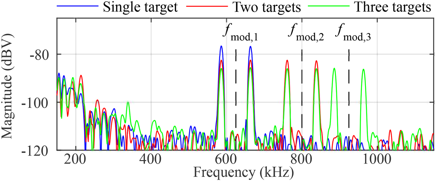
The available signal power is distributed among the different spectral components in this mode. Thus, the simulated RCS of each target is dependent on the number of the targets to be generated and the magnitude of the corresponding signal magnitude defined by  $A_{{\rm mod},p}$. In Fig. 11, an exemplary spectrum from measurements using a single reflector is depicted. In blue, the measurement shows the double-peaks in case of a single modulation frequency. In contrast to this the red and green curves represents the impact when a second and third modulation frequency is applied to a single MRN. The magnitudes have been set for a equal power distribution by
  $A_{{\rm mod},1}=A_{{\rm mod},2}=A_{{\rm mod},3}$. The multi-target generation is for instance suitable to reduce the speed for aquiring the calibration data over the whole IF-bandwidth, as for each single measurement multiple spectral components can be evaluated.

Fig. 11. Spectrum of a multi-target measurement setup using a single MRN supplied by up to three simultaneously modulation frequencies.
Measurement setup and results
In this section, two practically important aspects of the RTS are demonstrated. First, the characterization of a radar station is shown, secondly, different target configurations are investigated. Therefore a 24-GHz multi-channel radar system, based on Analog Devices ADF5904 receivers and a ADF5901 transmitter, generating a TX power of 20 dBm EIRP, is used. The base band stage is digitized by an AD8283 analog-to-digital converter (ADC) that integrates configurable amplifiers and low-pass filters. As depicted in Fig. 12, a host-PC is used to control the DUT, collect the measurement data and, to configure a signal source for generating the arbitrary modulation signals. These signals are then fed to the  $i=1\ldots I$ MRNs. The used parameters of the system are summarized in Table 2.

Fig. 12. A setup of the presented RTS for a measurement with four MRNs.
Table 2. System parameter set of the DUT

MRN characterization
Prior to the final RTS measurements, a characterization to investigate the impact of different modulation frequencies and signal shapes has been conducted. An important factor is the dependency of the reflected power from the modulation frequency  $f_{{\rm mod}}$ to ensure, that the desired RCS can precisely be defined. In an ideal setup, the RCS would be constant for every
  $f_{{\rm mod}}$ and only influenced by the on- and off-voltages or phase shifts as described in the Section “Radar cross section”. A further parameter of interest is the suppression of higher order harmonics caused by the modulation signal. Besides the presence of the virtual targets caused by the fundamental wave defined by
  $f_{{\rm mod}}$, additional unwanted targets can be found at the corresponding harmonic frequencies. The occurrence of these unwanted targets should be limited to a minimum to avoid a possible impact to the wanted virtual targets. The measurements have been conducted using a 24-GHz signal source to generate a well-defined reference RF-signal that is fed to a basic MRN switch. A spectrum analyzer then is used to determine the magnitudes of the fundamental, second, and third order harmonics of the modulation frequencies ranging from 0.1 to
  $100\, {\rm MHz}$ with an increment of
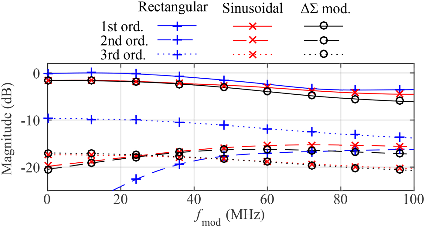
  $0.1\, {\rm MHz}$. In Fig. 13, the normalized results of the conducted measurements using a rectangular, a sinusoidal, and a signal generated by the usage of a
  $\Delta \Sigma $-modulator [Reference White, Cantrell, McConnell and Alter17] are depicted. The
  $\Delta \Sigma $-modulator is also used to emulate a sinusoidal signal. Up to a frequency of about
  $28\, {\rm MHz}$ the measured slope of the fundamental frequency is completely constant with a deviation of the magnitude well below
  $0.35\, {\rm dB}$ at the highest frequency. This states the possibility to operate the MRN-based RTS up to this frequency without the necessity of any further compensation. For higher frequencies the achieved reflected power of the fundamental frequency decreases in a smooth manner, so that for a high-precision magnitude calibration of this region, a compensation using look-up tables is applicable. A crucial result can be found in the comparison of the signal shapes. While the rectangular waveform offers a very good suppression of the second-order harmonic it lacks at the low suppression of about only
  $10\, {\rm dB}$ for the third-order harmonic. To reduce this effect a sinusoidal waveform has been applied resulting in a significantly better performance at the suppression. Depending on the available signal sources used for the generation of the modulation signal a complete digital approach is to use a
  $\Delta \Sigma $-modulator. Using this method the sinusoidal signal can be reshaped by fast switching between two fixed voltage levels, while a similar performance as for the pure sinusoidal modulation is achieved. In general, this characterization states the capability of the RTS to also be used with fast-ramping FMCW radar systems, where high IF signal components have to be expected.

Fig. 13. Comparison of the normalized slope of the fundamental, second-, and third-order harmonics caused by different modulation signals.
Target generation
In a first measurement setup, the principle capability to simultaneously generate multiple independent targets with different RCS, locations, and velocities is demonstrated. Therefore, four MRNs are mounted as depicted in Fig. 12 and set to emulate targets with different parameters. To limit the overhead of controlling the measurement and signal generation equipment, identical basic MRNs, fed with a basic rectangular modulation signal were used. Because of the superior suppression of the second-order harmonic, this also allows one to use closely spaced low-frequency modulation signals, beneficial for the visualization of the measurement outcomes. These rectangular modulation signals are generated by two-channel arbitrary waveform generators 33 520 from Keysight. The results are summarized in Fig. 14. To evaluate the accuracy the system can achieve for the simulation of various ranges, a conventional calibration of the radar module with a corner reflector has been conducted to eliminate the bias of the range. On the top, the IF spectrum of the scenario is depicted where each MRN can be clearly identified by the characteristic double-peaks centered at  $f_{{\rm mod}}$. The displayed values of the RCS are outcomes from simulations and in very good agreement with the measured values. In Table 3, the comparison between the true and measured distance compared with the aimed simulated distance can be found. There is a deviation of about
  $15 {\rm mm}$ for each MRN, that can be explained by the phase-shifting circuitry and feeding lines of the MRN itself, that have not considered at the calibration procedure. To display the AoA plot in the lower left corner a phase-calibration was performed for
  $s_{ {\rm MRR},m}^{+}$. The corresponding peaks can easily be identified while the signal power of
  $s_{ {\rm MRR},m}^{-}$ is spread in the slant-range domain leading to a suppression of these components. This is because the applied calibration has an inverse, defocusing effect on
  $s_{ {\rm MRR},m}^{-}$. An exemplary RD map of the scenario is depicted in the lower right corner.

Fig. 14. The spectrum, AoA, and RD map of a dynamic scenario is depicted. The RCS values are dependent on the simulated target distance and  $G_{ {\rm MRN}}$.
Table 3. True, simulated and measured MRN distances
IF-Chain characterization
In conventional radar unit characterization, static or moving corner reflectors are used to simulate target returns. If performed indoors the coverable range and thus testable IF bandwidth is limited to a few tens of meters or even less. In contrast to this, the RTS approach is capable of covering the full radial range by simulating any desired target distance, simply by the digitally controlled modulation frequency. The major purpose of the presented system is to seamlessly characterize the receivers transfer function across the total bandwidth of interest, including mixer, low-pass filters, and amplifiers. In a first setup, a single MRN was placed at a distance of 2 m directly in front of the radar unit. The modulation frequency was swept up to 10 MHz, virtually covering a range of 420 m and thus the full available bandwidth limited by the sampling rate of the ADC with  $f_{ {{s}}}=20\, {\rm MS/s}$. Because of the charateristic of the used ADC, only a single channel could be measured. Additionally, the RCS has been varied using the voltage levels depicted in Fig. 4 by the dotted lines. This measurement has been performed for two different cut-off frequencies
  $f_{ {\rm LP}}$ of the anti-aliasing lowpass. The outcome of this characterization is depicted on the top of Fig. 15, where 128 single measurements have been used for averaging. It clearly shows the impact of the different filter settings. The additional loss introduced by the limited mixers IF bandwidth and involved filters can be seen, especially for the wide-band filter. Furthermore, the results of the simulated variation of the RCS indicate a dynamic range of about
  $20\, {\rm dB}$ for the coarse tune setup modifying the on- and off voltages. In a second measurement run the sampling rate of the ADC has been reduced to
  $f_{ {{s}}}=5\, {\rm MS/s}$ and thus enables the system to sample four receive channels simultaneously. The integrated filters have been chosen accordingly to match the new sampling rate. Hence, the lower plots show the difference of the measured amplitudes and phase offsets between the channels. It can be seen that there is a deviation of up to 3 dB and large phase offset between the channels. This result shows that even although the channels are using identical RF- and IF-chains, non-negligible deviations at the estimation of a targets magnitude can be present. The results obtained here can directly be used as calibration data for the radar system. This is especially interesting for determination of the frequency-dependent I/Q phase- and amplitude-imbalance of complex receiver realizations.

Fig. 15. On the top, the normalized magnitude over frequency with variation of the desired RCS and different anti-aliasing filter settings for a single channel is depicted. The difference of magnitude and phase between the channels for a constant RCS is shown in the bottom.
Comparison and limitations
The simulator at hand can generate multiple independent targets in general, but it has to be noted that some conditions have to be considered. The most obvious condition is the occurence of the second peak and thus an additional but in most cases unwanted target for each modulation frequency. The presented system can be used to generate a completely arbitrary dynamic scenario but it has to be taken care of, that the signal processing of the radar system under test can be configured to ignore these unwanted targets. One way to encounter the double-peak situation is to use a second MRN switching circuitry and create a single-sideband modulation. First simulation and measurements underline the functionality of this concept, but further investigations and validations have to be done, which are out of the focus of this work.
For comparison of the presented system with the existing RTS [7], Table 4 gives a brief overview of several key features. The major advantage of the system at hand is its easy extendibility concerning multiple targets at different angles at very low costs. This eliminates the necessity for a mechanical movement, e.g. by a rotating table of the system and thus enabling a fast and simultaneous aquisition of calibration data for the complete IF-bandwidth as well as multiple angles in a single static setup.
Table 4. Comparison of presented system with existing RTS
 $^{\rm a}$ Depending on selected ramp parameters and signal source. The values given are derived from the used measurement setup; see Table 2.
 $^{\rm b}$ Same as (a) with assumption of
  $\pm 10\, {\rm ppm}$ deviation of signal source generating the modulation frequency at
  $f_{{\rm mod}}=1\, {\rm MHz}$.
Conclusion
In this paper, we presented the successful implementation of a novel RTS concept, based on the MRR. This approach is highly scalable, as every desired artificial target can be generated by a single, low-cost MRN. It gives the ability to nearly seamless and independently set distance, RCS and velocity of multiple targets in accordance with the selected parameters of the radar system under test. A wide selection of low-frequency and high quality signal-sources – necessary for the generation of the modulation signals – is commercially available for reasonable prices, giving the possibility to choose the right setup for the calibration and testing procedure. The modular setup enables fast simulation of targets at different angles to evaluate the angle-of-arrival capability of the tested radar. The system is applicable for CW and FMCW radar system characterization in an well defined indoor environment as necessary for an automated end-of-line test on a production site. Besides the generation of an arbitrary multi-target scenario, the key achievement is a fast characterization of the complete IF bandwidth, including magnitude and phase-difference for each channel. Thus a complete set of calibration data can be obtained in several seconds, demonstrating the future-readiness of the concept concerning high-volume, end-of-line radar system test applications.
Acknowledgments
This work has been supported by the Linz Center of Mechatronics (LCM) in the framework of the Austrian COMET-K2 programme.
 Werner Scheiblhofer received the Dipl.-Ing. (M.Sc) degree in Mechatronics from the Johannes Kepler University, Linz, Austria in 2009. In the same year, he joined the Institute for Communications Engineering and RF-Systems, Johannes Kepler University as Research Assistant. His research topics are radar system design and concepts for industrial radar sensors.
 Reinhard Feger was born in Kufstein, Austria, in 1980. He received the Dipl.-Ing. (M.Sc.) degree in Mechatronics and Dr. techn. (Ph.D.) degree in Mechatronics from Johannes Kepler University Linz, Linz, Austria, in 2005 and 2010, respectively. In 2005, he joined the Institute for Communications and Information Engineering, Johannes Kepler University Linz, as a Research Assistant. In 2007, he became a member of the Christian Doppler Laboratory for Integrated Radar Sensors, Johannes Kepler University Linz. He is currently an Assistant Professor with the Institute for Communications Engineering and RF-Systems, Johannes Kepler University Linz. His research topics are radar signal processing, as well as radar system design for industrial and automotive radar sensors
 Andreas Haderer received the Dipl.-Ing. (M.Sc.) degree in Communications Engineering from Technichal University, Graz in 2005. In the same year, he joined the Institute for Communications Engineering and RF-Systems, Johannes Kepler University as a Research Assistant. His research topics are microwave imaging systems and multidimensional radar-signalprocessing. He is the co-founder of the Inras GmbH where he is responsible for the design of modern RF radar systems.
 Andreas Stelzer received the Diploma Engineer degree in Electrical Engineering from the Technical University of Vienna, Vienna, Austria, in 1994, and the Dr. Techn. degree (Ph.D.) in Mechatronics (with honors sub-auspiciis praesidentis rei publicae) from the Johannes Kepler University Linz, Austria, in 2000. In 2003, he became an Associate Professor with the Institute for Communications Engineering and RF Systems, Johannes Kepler University Linz. Since 2008, he has been a key researcher for the Austrian Center of Competence in Mechatronics (ACCM), where he is responsible for numerous industrial projects. In 2007, he was granted a Christian Doppler Research Laboratory for Integrated Radar Sensors and since 2011 he isa full Professor at the Johannes Kepler University Linz, heading the Department for RF-Systems. He has authored or coauthored over 360 journal, conference, and workshop contributions. His research is focused on microwave sensor systems for industrial and automotive applications, integrated radar sensor concepts, SiGe-based circuit design, microwave packaging in eWLB, RF and microwave subsystems, surface acoustic wave (SAW) sensor systems and applications, as well as digital signal processing for sensor signal evaluation. Dr. Stelzer is a member of the Austrian Ö-VE. He has served as an associate editor for the IEEE MICROWAVE AND WIRELESS COMPONENTS LETTERS. Currently he serves as Chair for MTT-27 Wireless-Enabled Automotive and Vehicular Applications. He was recipient of several awards, including the 2008 IEEE Microwave Theory and Techniques Society (IEEE MTT-S) Outstanding Young Engineer Award and the 2011 IEEE Microwave Prize. Furthermore, he was recipient of the 2012 European Conference on Antennas and Propagation (EuCAP) Best Measurement Paper Prize, the 2012 Asia Pacific Conference on Antennas and Propagation (APCAP) Best Paper Award, the 2011 German Microwave Conference (GeMiC) Best Paper Award, as well as the EEEfCOM Innovation Award and the European Microwave Association (EuMA) Radar Prize of the European Radar Conference (EuRAD) 2003. He is a member of the IEEE MTT, IM, and CAS Societies and he served as IEEE Distinguished Microwave Lecturer for the period 2014 to 2016.