I. INTRODUCTION
Variable Z 0 (VZ 0) is a novel antenna design or optimization (D/O) methodology applicable without limitation to all D/O techniques that include feed system characteristic impedance or source internal impedance (Z 0) as a parameter. It can lead to better antennas across all wireless platforms by any performance measure, for example, gain, or pattern, or radiation efficiency, or, especially, impedance bandwidth (IBW), or any combination thereof.
The Internet of Things (IoT) is largely populated by wireless devices whose performance often is antenna-limited. Antenna research consequently has been identified as a key IoT technology [Reference Xiang and Li1]. Antenna D/O is especially important because IoT wireless device performance is highly dependent on the objects and materials surrounding the antenna which often degrade performance and make antenna integration difficult [Reference Mayordomo2]. Antenna design is a fundamental enabling technology for the IoT and, by extension, for the “Internet of the Future” and for intelligent wireless systems generally [Reference Tarricone3]. A critical IoT architectural element is base station antennas supporting wireless sensor networks and wide-area-coverage cellular networks [Reference Shen, Lu, Li and Xu4, Reference Guo, Huang and Qu5], and the pervasive urban IoT or “Smart City” concept relies on a variety of antenna-based technologies such as cellular and short-range wireless (bluetooth low energy, low-power WiFi, or IEEE 802.15.4) [Reference Andrea Zanella, Bui, Castellani, Vangelista and Zorzi6, Reference Jina, Gubbib, Marusic and Palaniswami7]. IoT devices are expected to number nearly 7 trillion by year 2020, all of them equipped with antennas requiring state-of-the-art D/O [Reference Kokkoniemi, Ylitalo, Luoto, Scott, Leinonen and Latva-aho8], an example of which is genetic algorithm optimization of an RFID antenna [Reference Xiong, Giuseppe, Occhiuzzi, Marrocco, Caizzone and Quijano9]. Every IoT antenna can benefit from VZ 0 because this technology mitigates traditional antenna D/O limitations by introducing another degree of freedom into the D/O process. An important feature of VZ 0 is its applicability to any IoT platform, indeed to all wireless devices or base stations of any kind.
The idea behind VZ 0 is extraordinarily simple, yet it has been overlooked through decades of antenna engineering. VZ 0 is a proprietary technology [10] that has been applied to the design of various antenna systems: ultra wideband (UWB) six-element Yagi–Uda array with more than 33% IBW (S 11≤−10 dB) [Reference Formato11]; multi-stub matching networks [Reference Dib, Sharaqa and Formato12, Reference Sharaqa, Dib and Formato13]; 3–12 GHz meander monopole [Reference Formato14]; and resistively loaded bowtie [Reference Formato15]. This paper describes VZ 0 technology and applies it to a high-gain UWB dipole. The prototype antenna is representative of a typical IoT base station antenna, but VZ 0 technology is equally applicable to any IoT antenna, especially antennas in small devices.
II. VZ 0 ANTENNA TECHNOLOGY
In all cases where the antenna feed system characteristic impedance or Z 0 is a design parameter, traditional antenna D/O assigns a specific fixed value, usually a “standard” value such as 50 Ω. The D/O process then identifies antenna structures consistent with this limitation, that is ones whose source current distribution results in an antenna input impedance that is sufficiently close to Z 0 (design) or as close as possible (optimization). A state-of-the-art example of this approach is an eight-element 2G/3G base station antenna employing quarter-wave transformer sections to match a 50 Ω feed [Reference Quan, Li, Wang and Cui16]. Another is a wideband sleeve monopole base station antenna covering the GSM, DCS, PCS, WCDMA, CDMA2000, TD-SCDMA, UMTS, and WLAN bands, also designed against a fixed 50 Ω feed [Reference Li, Yang, Liu and Jiang17]. The dual-band dual-polarization base station array utilizing a complex integrated Chebychev impedance transformer in order to match 50 Ω is a third example [Reference Moradi and Nikmehr18].
Unfortunately, this approach needlessly eliminates all source current distributions that provide better antenna performance without necessarily providing a “good” match to a predetermined fixed Z 0. VZ 0 overcomes this limitation by introducing Z 0 as a true variable quantity in the D/O procedure whose value is determined by the procedure. The resulting Z 0 may or may not be “workable” in the sense of adequately matching the radiofrequency (RF) source and the antenna, but clearly it should be considered in any prudent design approach because the VZ 0 antenna might be much better than the one matching some arbitrary, predetermined fixed impedance value. Section III of this note provides an example of improved antenna performance provided by VZ 0 technology.
III. OPTIMIZED WIRE-LOADED BROADBAND DIPOLE
The antenna considered here is a wire-loaded dipole in free space that is representative of an IoT base station antenna. It comprises a center-fed feed wire symmetrically disposed along the z-axis in a standard right-handed Cartesian coordinate system with each end symmetrically loaded by five wires. The optimization objective is high end-fire (+x-axis) gain and low-voltage standing wave ratio (VSWR) from 3 to 16 GHz covering the C, X, and Ku frequency bands. The prototype antenna is the structure-based evolutionary programming design (SED) dipole described in [Reference Casula, Mazzarella and Montisci19] (see also [Reference Fanti, Maxia and Musu20, Reference Casula, Mazzarella and Sirena21] for additional discussion). The SED antenna was designed against a fixed Z 0 = 200 Ω, which is not the “standard” 50 Ω value, but instead was chosen to match a typical bifilar transmission line. This requirement is an example of the unnecessary limitation that is completely avoided by VZ 0 because VZ 0 treats Z 0 as a true variable parameter to be determined by the D/O methodology.
VZ 0's utility is illustrated by applying central force optimization (CFO) [Reference Formato22–Reference Formato24] to the optimization of a structure similar to the SED dipole. CFO's decision space boundaries were set to encourage geometries similar to the SED dipole, but instead of specifying a fixed Z 0 = 200 Ω it was allowed to float in the range 175 ≤ Z 0 ≤ 250 Ω. Its ultimate optimized value was determined by the CFO algorithm instead of its being specified in advance. This simple step adds another degree of freedom to the D/O space which consequently now includes the myriad source current distributions needlessly excluded by insisting on a specific value of antenna input impedance in the first place. Therein lies VZ 0's potential to dramatically improve IoT and other wireless device performance.
Perspective views of the two optimized dipoles are shown in Fig. 1 (axis length 0.1 m). It is evident that the structures are quite similar. Performance was computed using the Numerical Electromagnetics Code (NEC) Ver. 4.2 [Reference Burke25]. Geometry for the SED dipole is tabulated in [Reference Casula, Mazzarella and Montisci19], and the corresponding NEC input file is shown in Fig. 2(a). Geometry data for the CFO-VZ 0-optimized dipole appear in its NEC input file in Fig. 2(b).

Fig. 1. Optimized dipoles, SED (a) and CFO-VZ 0 (b) (axis 0.1 m).

Fig. 2. NEC input files: SED-optimized dipole (a) and CFO-VZ 0-optimized dipole (b).
Each wire in the NEC method of moments model was divided into segments 0.2 wavelengths long at 16 GHz. The wires were 0.665 mm diameter loaded with a conductivity of 4×10⁶ S/m following [Reference Casula, Mazzarella and Montisci19]. The NEC 4.2 models were validated using the average gain test (AGT) with perfect electric conductor (PEC) wires [25 at p. 103], and the results are plotted in Fig. 3 (in [Reference Casula, Mazzarella and Montisci19] the commercially available HFSS program was used for validation). Ideally AGT = 1, but values within about 10% validate the NEC model. In a couple of narrow bands NEC's data might be very slightly questionable, but at all other frequencies both antenna models are accurate.

Fig. 3. (a) SED-optimized dipole AGT. (b) CFO-VZ 0-optimized dipole AGT.
VSWR is plotted in Fig. 4. While both antennas perform very well, it is apparent that the VZ 0 dipole's VSWR is better than the SEDs. The only difference between the designs is that the SED was optimized to match a predetermined fixed Z 0 = 200 Ω, whereas the CFO-optimized antenna allowed Z 0 to float as a true variable parameter as required by VZ 0 technology. CFO determined the optimal value to be Z 0 = 226.2 Ω.

Fig. 4. (a) SED-optimized dipole VSWR//200 Ω. (b) CFO-VZ 0-optimized dipole VSWR//226.2 Ω.
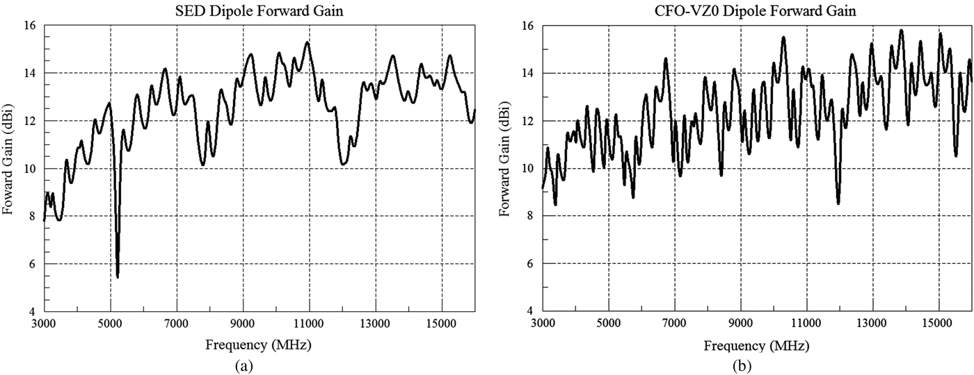
The other performance measure to be optimized was the forward gain plotted in Fig. 5. Examination of these data again shows that, while both antennas again perform very well, on average the VZ 0-optimized dipole outperforms the SED-optimized antenna.

Fig. 5. (a) SED-optimized dipole forward gain. (b) CFO-VZ 0-optimized dipole forward gain.
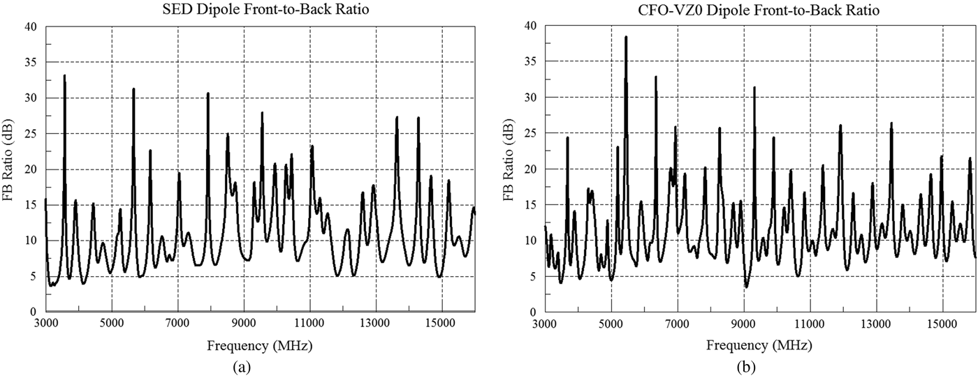
Although front-to-back ratio (FBR) was not an explicit design parameter in [Reference Casula, Mazzarella and Montisci19], it nevertheless was discussed as a performance measure and therefore is plotted in Fig. 6. Examination of these curves shows that the FBRs are generally quite similar across the 3–16 GHz band, yet an “eyeball average” suggests the CFO-VZ 0-optimized antenna is slightly better.

Fig. 6. (a) SED-optimized dipole front-to-back ratio. (b) CFO-VZ 0-optimized dipole front-to-back ratio.
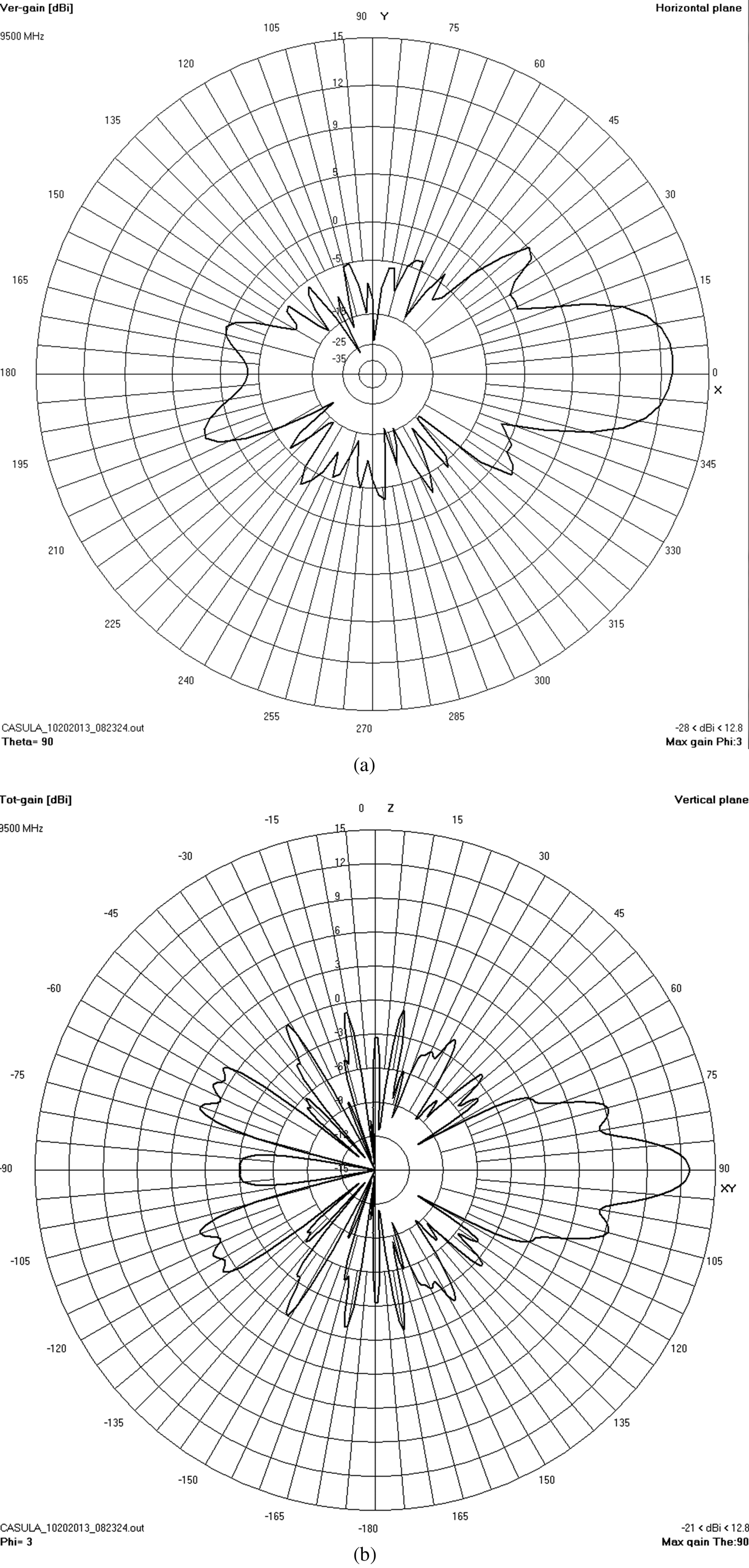
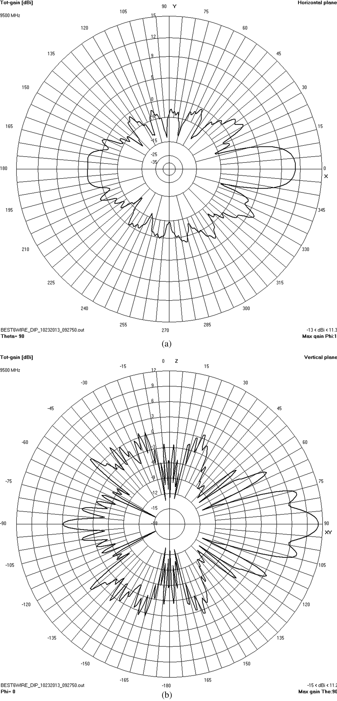
Figures 7 and 8 plot the 9.5 GHz horizontal and vertical plane radiation patterns in the plane with maximum gain as representative patterns. As expected, they are similar to those in [Reference Casula, Mazzarella and Montisci19] in which the lobing structure increases with increasing frequency as the antenna's electrical length increases.

Fig. 7. (a) SED-optimized dipole 9.5 GHz horizontal pattern. (b) SED-optimized dipole 9.5 GHz vertical pattern.

Fig. 8. (a) CFO-VZ 0-optimized dipole 9.5 GHz horizontal pattern. (b) CFO-VZ 0-optimized dipole 9.5 GHz vertical pattern.
IV. FUTURE WORK
In the future VZ 0 technology will be applied to a variety of antennas because of its universal applicability. As an example, it is being used to optimize wireless power transfer (WPT) antennas with quite good results. A typical structure designed using VZ 0 is the cylindrical multi-arm folded helix shown in Fig. 9. Its VSWR relative to a standard 50 Ω feed is quite poor, but by treating Z 0 as a true variable quantity the D/O methodology (in this case CFO) determined that the best feed system impedance is 142.05 Ω. That indeed this is the case evident from the NEC-computed VSWR and antenna input impedance plots in Figs 10 and 11, respectively, which show a nearly perfect impedance match to 142 Ω. And in spite of its small size this antenna provides nearly 2 dBi power gain as shown in the radiation pattern in Fig. 12. Another candidate WPT antenna geometry currently being studied is the planar multi-arm folded spiral shown in Fig. 13. Other future efforts will integrate VZ 0 with other D/O methodologies, for example, Pi Fraction Genetic Algorithm with Sibling Rivalry (πGASR) [Reference Formato26] or very simple optimization (VSO) [Reference Formato27].

Fig. 9. WPT multi-arm cylindrical helix (axis 0.05 m).

Fig. 10. WPT helix VSWR//Z 0 (a) and S 11 (b) with Z 0 = 142.05 Ω.

Fig. 11. WPT helix Z in = R + jX (a) and magnitude/phase (b).

Fig. 12. WPT helix radiation pattern.

Fig. 13. WPT planar spiral (axis 0.05 m).
V. CONCLUSION
This paper describes how VZ 0 antenna technology can dramatically improve antenna performance, especially for IoT base stations and wireless devices. The SED dipole was optimized against the predetermined fixed value Z 0=200 Ω, and as a result every antenna design that provided better maximum gain and better VSWR relative to a different reference impedance was automatically excluded from the decision space at the very outset of the SED procedure. By contrast, CFO converged on a different optimal value for Z 0 because Z 0 was allowed to float as a true variable quantity, that is, simply another unknown design parameter to be determined by CFO no different than the endpoint coordinates of the dipole loading wires. This single change in setting up the D/O methodology, whether it be CFO, SED, or any other technique, expands the decision space by including all antenna structures whose source current distributions provide better performance without regard to meeting a predetermined fixed impedance value. In this case, the CFO-VZ 0-optimized dipole's impedance of 226.2 Ω happens to be fairly close to the SED-optimized fixed value of 200 Ω, which is not surprising because the CFO-optimized antenna was constrained to be similar in structure. Its performance, however, clearly is better than the SED dipole's.


