


1. INTRODUCTION
One of the most popular research areas in ubiquitous or pervasive computing is the development of location-aware systems (Ferraro and Aktihanoglu, Reference Ferraro and Aktihanoglu2011). There are an increasing number of systems in which electronic devices provide the users some kind of information or service depending on their location. The essential component of a location-aware system is obviously the location-sensing mechanism. This important part is usually where the major problems and questions arise, depending on several constraints like the type of environment, the available technology or simply indoors or outdoors. The most widely used location system in the world is the well-known Global Positioning System (GPS), a Global Navigation Satellite System (GNSS). However, a GNSS is not typically usable indoors as it requires direct line-of-sight to satellites. In the indoor localisation problem there are approaches that use electromagnetic signals, ultrasound or a combination of these. Others do not use external signals and rely on the use of inertial measurement units that determine position by dead reckoning (Gu et al., Reference Gu, Song, Li and Ma2014). They all have strengths and weaknesses and may be very useful in their respective application domains (Deak et al., Reference Deak, Curran and Condell2012).
In general, distances or angles are estimated to a fixed set of anchors and the relative position to these references is calculated (Singh et al., Reference Singh, Kumar Sahoo and Ranjan Pradhan2012). However, this relative position is only useful if the target mobile device has some kind of mapped relation to these anchors. It requires knowledge of the infrastructure it is in. To attain the liberty of worldwide self-localisation without previous knowledge of the infrastructure, the signal which will be used to measure distances or angles should carry information about the emitting anchor's global position and maybe some relevant environmental information, such as the temperature, for instance, as this affects the propagation velocity of some signals. Conveying that information effectively in the signal emitted by the anchors will be crucial to allow global localisation indoors.
The main contributions introduced in this paper are the presentation of a newly developed method for reliable indoor global self-localisation of a mobile device through a non-ideal channel, supported by experimental results of this new method using perceptively masked sound as the signal of interest. As far as the authors know, this approach was never presented before considering this application.
In the next section our perspectives of the most relevant concepts and methodologies involved in determining localisation are presented, including a brief analysis on how existing indoor localisation approaches achieve it. In Section 3 the method to transmit data from the reference anchors to the mobile device is presented. In Section 4 an indoor localisation approach by using imperceptible audio is unveiled while presenting an experimental setup. Section 5 provides the experimental results and their discussion. A summary of the findings is given in the conclusion, in Section 6 together with presentation of lines for future work.
2. BACKGROUND AND RELATED WORK
An anchor-based localisation system is one that relies on devices emitting signals from fixed locations to determine position of mobile devices that are located among them.
Anchor-based systems localisation depends upon distance or angle between anchors to obtain unknown Mobile Device Positions (MDP) (Amundson and Koutsoukos, Reference Amundson and Koutsoukos2009; Deak et al., Reference Deak, Curran and Condell2012).
The first step is determining the distances or angles. Depending on the application or type of signal used by the anchors, several techniques can be employed. The most common are:
-
• Time of Arrival (TOA);
-
• Return Time of Flight (RTOF);
-
• Time Difference of Arrival (TDOA);
-
• Angle of Arrival (AOA);
-
• Received Signal Strength (RSS);
-
• RSS Profiling/Fingerprint.
The second step is to estimate location by combining the distances or angles (Muñoz et al., Reference Muñoz, Bouchereau, Vargas and Caldera2009). Depending on the approach, the use of ranges obtained by the time-of-flight of the signal, or from the angles where the mobile device is found, several techniques can be employed. In this work TOA is used and Figure 1 describes its mechanism. The quantity t1 is calculated from the time duration of the signal travel between A1 and the Mobile Device (MD).

Figure 1. TOA position estimation methodology, from left to right, using three anchors to determine mobile device's position (MDP).
Multiple measurements may be obtained from various anchors and subsequently combined in an optimal or suboptimal way to obtain an estimate of the position of the mobile device. This process of obtaining a position estimate from multiple observations is usually referred to as multilateration. Whenever the number of observations reduces to three, then the process is referred to as trilateration, or triangulation, which corresponds to classical geometric concepts.
Localisation is generally obtained from mappings or geometric relationships that convert measured quantities into coordinates, sometimes from the optimal solution of nonlinear and over-determined systems of equations when the number of relevant anchors exceed three. Finding the receiver position is not a trivial task because these measurements have nonlinear relationships with position (Zekavat and Buehrer, Reference Zekavat and Buehrer2011).
Multilateration models can be generally stated as obeying Equation (1):
 $${\bi r} = f\left( p \right) + {\bi n},$$
where r is a measurement vector, p is the unknown mobile's position, f(p) is a known nonlinear function of p and n is an additive noise vector with zero mean.
Nonlinear methodologies directly employ Equation (1) to solve for p by minimising a Least Squares (LS) or a Weighted Least Squares (WLS) cost function constructed from the following error function:
 $${e_{nonlinear}} = {\bi r} - f\left( {\tilde p} \right),$$
Where
 $\tilde p = {\left[ {\tilde x\; \tilde y} \right]^T}$
is the optimisation value for p, which corresponds to the Nonlinear Least Squares (NLS) or Maximum Likelihood (ML) estimator, respectively. Alternatively, one simple linearization scheme may be used for expansion of Equation (1) into a set of linear equations in p :
$\tilde p = {\left[ {\tilde x\; \tilde y} \right]^T}$
is the optimisation value for p, which corresponds to the Nonlinear Least Squares (NLS) or Maximum Likelihood (ML) estimator, respectively. Alternatively, one simple linearization scheme may be used for expansion of Equation (1) into a set of linear equations in p :
 $$b = Ap + {\bi q},$$
where b and A are available, while q is the transformed noise vector. Based on Equation (3), one can obtain
 $${e_{linear}} = b - A\tilde p.$$
Equation (4) can be used to effectively estimate position by applying least-squares based techniques like LS, WLS techniques, Linear Least Squares (LLS) (Chen et al., Reference Chen, Hudson and Yao2002; Fenwick, Reference Fenwick1999), Weighted Linear Least Squares (WLLS) (Cheung et al., Reference Cheung, So, Ma and Chan2006) or subspace-based estimators (Cheung and So, Reference Cheung and So2005; Wei et al., Reference Wei, Wan, Chen and Ye2008) depending on the advantages/disadvantages of each technique. In this work, the NLS estimator is used with the Gauss-Newton method, due to its high accuracy and because it does not require noise statistics (Zekavat and Buehrer, Reference Zekavat and Buehrer2011).
Once a MDP estimate is achieved, it is necessary to express it in a global localisation reference. Knowing the MDP relative to a set of anchors will only localise it in that area. To convert the MDP relative to a set of anchors into global coordinates may be done after knowing the anchors' global positions. That can be achieved at the MD side of the system by identifying the previously registered indoor space with its unique characteristics (received) and reading the absolute position of each identifiable anchor from an existing database, or by having each signal sent by the anchors transmit their absolute position and any other relevant data. The latter option requires no previous information of the space and is therefore more interesting - it resembles GNSSs, which do not require knowledge of the geographic place where the receiver determines its global position.
3. TRANSMITING DATA FROM ANCHORS
There are many advantages in using a passive localisation method. The most relevant ones are related to security, privacy and autonomy. The typical GNSS is an example, as the satellite constellation is not aware of the activity of the receiver. A simple GNSS receiver achieves global positioning just by having satellites line-of-sight and, similarly, an indoor mobile device may do so just using signals already available in that space, with similar advantages (Kaplan and Hegarty, Reference Kaplan and Hegarty2005). However, a reliable one-way communication between anchor(s) and a mobile device through a shared multi-use noisy channel (many times with impulsive background noise) with strong fading and multipath and populated with persons is not a simple task to achieve.
In the approach presented in this paper, in which information concerning the anchor's position travels through the channel embedded in the signal, successful data transmission is critical. Even if the MDP with respect to the anchors is precisely determined, if the anchor positions are wrong due to bad reception this will result in bad positioning, localisation estimation can be the wrong indoor infrastructure. Therefore, the data transmission problem must be assumed as one of the most important parts of this global localisation system. Therefore redundancy, error detection/correction and filtering techniques are employed to avoid significant errors.
The chosen position format to transmit global position was the Universal Transverse Mercator (UTM), typically described by a grid with latitude and longitude in metres. This rectangular format was chosen for being the most universally accepted by Localisation-Based Applications (LBA) and one that provides faster and simpler calculations. The MDP can be estimated by the NLS method just by “adding” the rectangular components of the range vector to the anchor's position. A polar format, for instance, would require conversion and using a different reference.
Resolution in the representation was taken to the centimetre-level, as may be seen in the following example, in Figure 2, displaying the actual coordinates of one of the anchors (anchor 1) of our experimental setup:

Figure 2. UTM format example at position of anchor 1 in the experimental setup.
As can be seen in the above example, to transmit a global position with centimetre resolution, a substantial amount of data is required. The strategy used was to encode that information into a block of data that is broken down in groups of three characters. Letters from the grid or from the cardinal directions were encoded with a two digit numbering according to the UTM standard. Each of these groups is then converted into a fixed length binary word and is sequentially transmitted. In Figure 3 the full string is separated in three character groups (12 bits necessary for binary transmission with Golay codes as will be seen ahead):

Figure 3. UTM string data packing in three character groups.
The conversion of the three characters to binary 12 bit words is illustrated in Figure 4.

Figure 4. UTM string in 12 bit binary words.
Transmitting the 108 information bits directly is not a good methodology. Indeed, a simple misinterpretation of one of the most significant bits of the most left side characters group of the grid, latitude or longitude, will result in an intolerable error. In this situation, errors with the same Hamming distance would result in very different consequences. Since it is not possible to generate the error signal and request retransmission, as is done in many difficult communication channels, simple error detection is not enough. Therefore it is very important to employ other solutions and the use of Forward Error Correction (FEC) appears to be very convenient. To do so, Golay codes (Golay, Reference Golay1949) are used to encode the data allowing error detection and correction to a significant extent. In this application, where a processing may probably be held by a device with limited computation/battery autonomy, Golay codes are the preferable choice among other error correcting tools like, for example, Reed Solomon codes (Guven, Reference Guven2014), due to their relatively small computational complexity of O(n). Their historical use in times where computational power was not as high as it is now, like in deep space communications (Truong et al., Reference Truong, Holmes, Reed and Yin1988), has proven their validity in applications where device battery duration is a concern.
A Golay codeword is formed by taking 12 information bits and appending 11 check bits which are derived from a modulo-2 division as depicted in Figure 5.

Figure 5. Golay [23,12] codeword structure.
The common notation for this structure is Golay [23,12], which means that the code has 23 bits in total with 12 information bits, and consequently 11 check bits. Since every codeword is 23 bits long, there are 8388608 possible binary values. However, since every one of the 12 bit information fields has only one corresponding set of 11 check bits, there remain only 212 = 4096 valid Golay codewords. The Golay codewords are not really evenly distributed. Instead they are spaced regarding the Hamming distance between them. A Golay codeword has seven or more bits differing from any other. Therefore the code has a minimum distance d of seven. It has been proven analytically that the Golay code can detect/correct a maximum of (d − 1)/2 = 3 bit errors, in any possible pattern. As these codes are perfect, it is not possible to know that their capacity has been exceeded. Therefore, a possible extension of the Golay codes adds an overall parity bit, resulting in a very easy to use three-byte codeword called the extended Golay code, noted as Golay [24,12] and represented in Figure 6. With this extra bit, if the reception mechanism indicates an odd number of errors and this bit is correct, then the information is unrecoverable (Houghton, Reference Houghton2012).

Figure 6. Golay [24,12] codeword structure with parity bit.
Golay codes therefore handle random bit errors as they tolerate three bit errors per 24 bits (a codeword) - a 12·5% bit error rate compensating the fact that data retransmissions cannot be requested by the receivers operating passively.
The Golay codeword has useful properties regarding its use in data transmission:
-
• Cyclic Invariance. A 23-bit Golay codeword may be cyclically shifted by any number of bits and the result is also a valid Golay codeword;
-
• Inversion. An inverted 23-bit Golay codeword is also a valid Golay codeword;
-
• Minimum Hamming Distance. The Hamming distance between any two Golay [24,12] codewords is always eight or more bits;
-
• Error Correction. The correction mechanism of Golay decoding can detect and correct up to three bit errors per codeword.
However, the acoustic channel is prone to burst errors and many consecutive data bits may be corrupted. An impulsive additive noise is an example of cause of a burst error which can compromise successful data reception. Golay codes are not able to correct bursts of errors over three bits long in a codeword, so averaging and interleaving techniques should be performed to avoid the effects of larger burst errors. In the presented example, the 216 bit Golay encoded locations (nine 24-bit codewords with parity) are therefore transmitted several times to ensure that the receiver may average out and decode its Golay code to rebuild the original sequence.
4. LOCALISATION WITH AUDIO SIGNALS
The possibility presented here is the use of an anchor-based audio indoor localisation approach in a difficult scenario. An audio signal is one of the most complicated types of signal to use, as it imposes several constraints and is affected by the acoustic environment. However, it also has several advantages especially concerning its electro-acoustic technical simplicity and its possibilities. Audio-capable devices are present in people's everyday life and when one considers a possible usage scenario for this purpose, it is easy to assume loudspeakers may be used as fixed anchors and smartphones (with their microphones) as mobile devices, as represented in Figure 7. This would allow a wide dissemination of the indoor localisation possibilities to everyone in every public space. These approaches are usually classified as based on signals of opportunity (Merry et al., Reference Merry, Faragher and Scheding2010), because in these spaces the normal situation is the existence of natural or artificial background noise and artificial sound production.

Figure 7. Example illustration of the concept of transmitting the absolute anchor's position in the range determination signals to allow the mobile device to globally localise itself. Some of the channel effects are also enumerated to illustrate the significant changes found in the resulting received signals at the microphone of the mobile device.
Nonetheless, the apparent implicit frailties associated with the use of audio signals for this application (people's perception, maximum range, etc.), together with a difficult to use, highly fading acoustic channel inside a room atmosphere (also affected by multipath, interference, etc.), create several challenges that need to be overcome.
4.1. An Indoor Audio Sound Localisation System
Considering that one of the requirements for allowing universal compatibility in a localisation system is minimising installation costs, it is desirable to use only anchors that may be already installed. Therefore one cannot assure a favourable anchor distribution architecture but instead an already available one, hopefully implemented to allow good sound coverage for the voice frequency range. This is usually a mandatory legal requirement in public spaces for emergency calls situations.
The use of acoustic signals in indoor localisation signals has been explored in solutions using ultrasound (Brignone et al., Reference Brignone, Connors, Lyon and Pradhan2003; Prieto et al., Reference Prieto, Jiménez and Guevara2007; Suzuki et al., Reference Suzuki, Iyota, Choi, Kubota and Watanabe2009), or near ultrasound audio signals (Aguilera et al., Reference Aguilera, Paredes, Alvarez, Suarez and Hernandez2013; Lopes et al., Reference Lopes, Vieira, Reis, Albuquerque and Carvalho2014). However, using such higher range frequencies in sound signals will require a dedicated or larger emitter installation, so that a sufficient coverage is assured over the indoor areas, due to their usually much narrower radiation directivities.
The present approach, using audio signals, explores established technologies (both on the physical setup of the indoor space and in the mobile device) and the wider directivity (and therefore wider coverage) that audio transducers have at not so high range frequencies. This will allow using pre-existent sound systems and minimising installation costs. The apparent problem of having the people hear the sounds is overcome with the use of data hiding techniques like Echo Hiding (EH) or using Spread Spectrum (SS) modulation.
Using v to represent the speed of sound together with the time of Time-Of-Flight (TOF), the distance d can be calculated:
 $${\rm d} = {\rm TOF\;} \cdot {\rm v.}$$
To find the distance d in Equation (5) the TOF of each vector between one of the anchors and the mobile device is measured through its TOA by finding the peak of a correlation result waveform between the signal that was sent and the received signal (see Figure 8).

Figure 8. TOA-based audible sound localisation system method illustration. An example of four anchors and a mobile device (m) where a correlation technique will be employed to estimate the TOF and consequently to find the distance vectors lengths d1, d2, d3 and d4.
The generalized cross-correlation phase transform algorithm has proved to be successful in providing sharp peaks on the place of the signal event even in noisy environments (Moutinho et al., Reference Moutinho, Araújo and Freitas2013), facilitating the TOF estimation, when compared with other similar techniques.
If the receiver clock is not in synchronism with the infrastructure and t 0 is not known, the TOF cannot be measured directly. However, in order to overcome this difficulty without turning over to Time Difference Of Flight (TDOF) it is possible to set an initial upper bound of t 0 and perform “pseudo-range” calculations that will consequently result in distance overestimations with equal offset. Then, the circles intersection area may be minimised through local search and t 0 may be found. It is also possible to ease the process by transmitting timing information within the signal that will help in reducing the solutions space.
Measuring distances with this process will allow the mobile device to estimate the localisation relative to each anchor. If the signals convey information regarding the anchor's absolute global position, the mobile device may transform its relative position into a global one. This justifies the need to transmit information in the acoustic signals.
4.2. Data Hiding techniques
4.2.1. Spread Spectrum
Using a psycho-acoustic model (Garcia, Reference Garcia1999; Johnston, Reference Johnston1988; Proakis, Reference Proakis2003), this technique computes a frequency-masking threshold value, multiplies the transmit signal by a Pseudo-random-Noise (PN) series, and superimposes the signal spread across the entire frequency band so as to fall below the frequency-masking threshold value (Hatfull, Reference Hatfull2011). The watermark-like content is hidden by taking advantage of two characteristics of the human auditory system. Frequency masking exploits the fact that humans cannot perceive tones of slightly differing frequencies when one is played with substantially smaller intensity. Temporal masking relies on the fact that when sounds are played shortly before or after similar sounds of higher amplitude, they are imperceptible. With the spread-spectrum encoding technique, a PN sequence is turned into a low power signal spread across a widespread frequency interval. This is different from schemes that encode their data in the time domain. Each loudspeaker's PN sequence should be statistically uncorrelated so that each anchor signal is correctly identified. A sum of PN sequences results in Multiple Access Interference (MAI) which is approximated by a Gaussian noise process (following the central limit theorem in statistics) which may be masked in the background environmental noise becoming almost imperceptible. Gold codes are a suitable example of a PN for this purpose as the cross-correlation between codes is low.
Gold codes are useful since a large number of codes can be generated with good auto-correlation and cross-correlation properties (Boney et al., Reference Boney, Tewfik and Hamdy1996), which will be necessary to allow identification of each one of a set of anchors. Each data package is therefore identified by its code that spreads the data. Once the transmission information is set in 24-bit Golay codewords, Direct Sequence-Code Division Multiple Access (DS-CDMA) may be used to transmit the unique wide band coded signal using a modulation scheme such as Binary Phase-Shift Keying (BPSK).
4.2.2. Echo Hiding
This method uses the reduced human perception of short-range echoes to hide information by adding one of two different kinds of sub-perceptible echoes to segments of the cover audio that can be interpreted at the reception as Figure 9 illustrates (Gruhl et al., Reference Gruhl, Bender and Lu1996). Recovery of the data is accomplished by using cepstral analysis to detect echoes in the transmitted signal in order to discern which type of echo occurs in each segment of the signal. Translating the series of echo types into a binary string will recover the data.
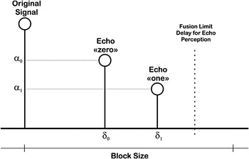
Figure 9. Echo Hiding kernels illustrating the introduced echoes to transmit “zero” or “one” symbols in each block.
Using echoes to encode information makes the information resilient to some interferences and perturbations. However, echo hiding bases itself on information serially encoded into chunks of the cover audio, which leaves it vulnerable to some impulsive overlaying sounds. Additionally, echo hiding is vulnerable to situations where natural echoes occur and can confuse the reception mechanism. Nevertheless, in situations where there is audio background (music or speech), it is very useful in allowing us to transmit data without affecting people's comfort and avoiding their perception of the transmission.
4.3. Localisation Experiments Description
Localisation experiments were conducted in a research laboratory room with 7 m x 9 m x 3 m size using a side area of 6 m x 7 m. The room includes all common types of furniture and electronic laboratory equipment and computers. It has plaster reverberant walls, of which two are exterior walls and three large glass windows. Persons and their normal acoustic behaviour were included. This physical space was not adapted in any way for this experiment. Twenty-three “ground truth” points were uniformly chosen through the area and marked on the floor to measure estimation errors in the test space. Four ordinary 2·5 inch full-range satellite loudspeakers were used as anchors and were wall mounted at ear level (1·65 m) and distributed according to Figure 10.

Figure 10. A perspective view of the experimental setup without most of the furniture for a clear view.
Localisation experiments were performed using TOA measurements from Long Code Direct Sequence Spread Spectrum (LC DSSS) signals containing a different 127-bit gold code for each of the four loudspeakers. In previous work (Moutinho et al., Reference Moutinho, Araújo and Freitas2013) the experimental setup used to perform localisation using audio signals was described in detail. The generalised cross-correlation phase transform was used for detection and estimation of the signals’ TOA and the position estimation from the noisy measurements was achieved by the Gauss-Newton non-linear methodology to perform local search and minimise the error.
In Table 1 it is possible to observe the average error in localisation, depending on the position of the room. Central points are considered the ones that are more than 2 m away from walls in the centre of the room. Peripheral points are the remaining ones and will suffer more severely from multipath and near-far effects. Although a centimetre-level error was achieved, the peripheral points’ errors were still more than four times larger than the central points. No significant near-far effect was felt, even in the localisation points closer to walls, as the emitted signal's intensity was small (to minimise people's perception of added audio content). The necessary proximity to the loudspeakers to be affected by this effect is not foreseen, as the loudspeakers are usually not close to people (ceiling, corners or walls in elevated positions. Nevertheless, the developed methodology predicts such a scenario as it evaluates this situation. When only one loudspeaker signal is being successfully received, localisation estimate is set at its position (if it is that close, it is there).
Table 1. Indoor localisation average estimation error in central areas and close to walls.

4.4 Data-hiding Experiments Description
In the previously performed experiments, the results presented in Table 1 demonstrate the viability of using SS signals to localise a mobile device in an indoor environment. Considering this relevant result, the objective is now to assess the possibility of transmitting information embedded in the signal to allow the mobile device to locate itself globally. A proposed sequence of operations to reach this goal is illustrated in Figure 11.

Figure 11. Transmission, channel and reception block diagram: the modules used for sending and receiving the UTM global position string are illustrated.
Experiments were performed considering a 44,100 Hz sampling frequency and using the impulse response of a large conference room in compliance with the International Telecommunication Union (ITU) standards. The chosen Room Impulse Response (RIR) (Jeub et al., Reference Jeub, Schäfer and Vary2009) is characterised by having the receiving microphone four metres away from the loudspeaker in an “Office”-like environment with an average reverberation time for 60 seconds (RT 60) of 0·43 s. Additive White Gaussian Noise (AWGN), generated by a uniform random number generator, was added at the received signal to simulate possible background noise that would occur in the environment in a real situation. The anchor's global position has been sent in the UTM position string according with the previously stated protocol.
The data hiding method's parameters, presented in Table 2, were defined to maximise bit rate while preserving robustness and minimising any possible annoyance to people. In a global localisation application, where data transmission is necessary, Spread Spectrum parameters may require adjustment that will lower bit rate to maximise robustness.
Table 2. Data hiding parameters used in the presented results.

In the Spread Spectrum experiment the long-code methodology was used with 127-bit gold codes with a code frequency of 4410 Hz. Binary-Phase Shift Keying modulation was used with a central frequency of 13·230 kHz, still in the audible range even at both limits, but interpretable as noise in the frequency domain. The wide bandwidth provided by the PN code allows the signal power to drop below the environmental noise threshold, minimising people's perception without loss of information. Echo hiding parameters were selected considering the best possible bit rate and reliability while minimising any possible psycho-acoustic effect on people. Considering the Haas Effect, any later arriving sound (echo) should be within a 25–35 milliseconds time windows so that the sensory auditory system does not perceive another separate sound. On the other hand, the larger the delay, the more any delay affects the acoustical image by altering the original sound spatiality. Both delays (for the zero and one symbols) were selected far from the limit and separated enough to discriminate them and their difference well. Echoes’ amplitudes where also chosen as half the original (-6 dB) to control the spatial effect of adding echoes. Block size was set according with the literature and considering the necessary time to have sufficient samples to ease the echo detection process at reception.
5. EXPERIMENTAL RESULTS AND DISCUSSION
5.1. SS Transmission
In SS, Signal to Noise Ratios (SNR) were measured considering the signal to be the introduced SS component and the noise to be the background inserted noise. Bit Error Rates (BER) were calculated considering the bit-loss in the process of spreading-modulation-channel-demodulation-de-spreading, which is the same as comparing the 24-bit codewords at emission and reception. The Hamming distance reflects the number of bit differences between the original 12-bit information words. Reception will be correct only if there are fewer than four errors per codeword, otherwise the 12-bit part of the information will be wrong and a large position error can occur due to that.
When using SS with no other sound emission from the loudspeakers, one obtains an interesting performance when transmitting information. Table 3 depicts results of transmitting nine words of 24-bit information with the global position of the anchor at 600 bit/s. Together with Golay codes, one can observe successful transmission even with very low SNR.
Table 3. SS most prominent results with no other emission.

Although with a BER of 8%, data reception was successful for an SS signal emitted at 4·86 dB below background noise, making the signal imperceptible. This is due to the error correcting capabilities of Golay codes. It is important to notice that one could expect Golay code correction for 27-bits (9 words x 3-bits). However, in the first case of Table 3, the 21 errors were not uniformly distributed. This means that just one codeword with 4-bit error is enough to collapse data reception. This emphasises the need to operate inside a safe margin.
Using the same SS technique while reproducing music, results presented in Table 4 demonstrate a foreseeable smaller robustness.
Table 4. SS most prominent results together with music.

When the SS component is approximately 10 dB above noise it becomes perceivable. In this experiment, the 17 dB SNR (necessary for correct data reception as seen in Table 4) is not suitable for the purpose of avoiding people's awareness of added content. A different approach is required and Echo Hiding is the explored alternative for those intervals when music or voice is being reproduced.
5.2. EH Transmission
Echo Hiding has provided very good results in data transmission when music or voice are being transmitted. Even the more acute listener may have difficulties in perceiving that data is traveling along with music or speech.
In Table 5 the results demonstrate that even in low level emission scenarios (background music/voice) data is successfully transmitted at 16 bit/s. In these experiments, the music/voice is considered the “signal” in the SNR calculation. Again, the same UTM position string with nine parts of 24-bit words is transmitted without redundancy to allow demonstrating the method's robustness.
Table 5. Echo Hiding most prominent results in a music frame.

A 9·28 dB SNR in a music frame is associated to background quiet music, and the reception of data is successful. However, when voice frames are used, results improve greatly to a value of 6·55 dB as it is possible to observe in Table 6. This is probably associated with multipath interference in which the relative simplicity of the voice signal provides less interference to the correct interpretation of the included echoes that contain the information.
Table 6. Echo Hiding most prominent results in a voice frame.

Although no redundancy was used in these Echo Hiding experiments, it is possible to observe the error correcting effect of Golay codes. Hamming distances of three and below are corrected providing correct data reception. The other cases fail to provide the anchor's position.
A near 3 dB difference was found in the use of music relative to speech. However when the signal is speech with long pauses between words, as in the experiment results of Table 6, it causes some difficulties to the method because it requires acoustic content on the original signal to mask the echoes containing the information. Adjusting the frame size to the longest possible pause time in speech will avoid this, however it will lower data rate and consequently the necessary time to transmit a full data sequence.
5.3 Final Observations
All facts considered it is possible to assume that, regarding information transmission, SS is a valid method for the intervals with no emission on the public address sound system. In contrast, Echo Hiding is not suitable for those time frames, and is suitable for music or voice streams. Together, both can serve the purpose of complementarily transmitting data from the anchors (standard commercial loudspeakers) to a mobile device which is capable of receiving and processing them accordingly in a robust and computationally viable way. A practical application requires a detection mechanism of the audio content that is being transmitted by the public address sound system, to choose the most appropriate method to effectively convey the information so that it remains unnoticed. This is achieved by delaying the live signal (music, voice or silence) for quite a short period of time to allow the classification of the signal and to use the most appropriate data hiding technique. This short delay will not be a problem in the actual transmission as the audio content is typically for paging, messaging, entertainment or information purposes and a short delay does not compromise the communication.
The use of Golay codes with their forward error correction capability enables the use of a lower signal level and consequently minimizes the disturbance that one may expect while transmitting in an indoor public space in the audible sound range.
In its most impressive result, the SS experiment with no simultaneous audio background content being emitted was able to successfully emit the anchor's global position at 4·86 dB below environmental noise, an almost completely imperceptible addition to the background noise as illustrated in Figure 12, allowing the mobile device to locate itself globally.

Figure 12. Direct Sequence Spread Spectrum signal modulated with binary phase-shift keying lying approximately 5 dB below environmental noise.
6. CONCLUSIONS AND FUTURE WORK
Transmitting data robustly through the acoustical channel in indoor reverberant noisy spaces was a sizeable challenge. However, it was a worthwhile effort as it allows locating mobile devices globally without prior knowledge of the space, just as GNSSs provide outdoors.
It was demonstrated that it is possible to transmit data robustly (albeit with relatively low data throughput), while concealing it from people's perception.
Results presented here imply that the method required for concealing information in the acoustic environment depends on the programme that is being emitted by the public address sound system. When no sound is being reproduced, a Spread Spectrum low amplitude, barely audible signal is successful. When sound (music and/or voice) is being played, an almost imperceptible Echo Hiding technique is employed instead, transmitting data robustly.
Previous results demonstrated that a relatively precise indoor localisation is possible using audible sound. In this paper, new possibilities were explored to also transmit information through a barely perceptible signal in order to allow a mobile device to globally localise itself. Combined, both results validate the use of the audible sound range as a useful and promising range for the solution to the indoor localisation problem.
Future work will focus on sending timing information to ease TOF measurements and therefore increase performance in localisation estimation (as in the GNSS technologies). Additionally, the possibility to reduce the amount of information transmitted by the infrastructure, by using Cell ID localisation or Assisted GPS in Mobile Station Assisted mode (both possible indoors) to fill the leftmost significant part of the position information of the anchors, will be explored. These less accurate methods may be good enough to reduce the geographic ambiguity and avoid transmitting the full global position string, with a corresponding increase of efficiency in position determination and a greater position refresh rate.
ACKNOWLEDGEMENTS
A word of appreciation to I. de Medeiros Varzielas and Bruno C. Bispo for comments on the manuscript.
FINANCIAL SUPPORT
This work received support from FCT - Fundação para a Ciência e a Tecnologia, under the grant with reference SFRH/BD/79048/2011.


