


Paediatric pacing first began in 1956 with Walton Lillehei’s surgical team in the University of Minnesota to manage children with postoperative heart block.Reference Jeffrey 1 This was achieved by connection of a temporary myocardial pacing wire from the surface of the heart to an external stimulator. The success of this approach to reduce postoperative mortality drove further work on the development of an internal implantable pacemaker. For this, Lillehei turned to Earl Bakken, a young engineer who owned his own medical electronics shop, Medtronic.Reference Jeffrey 1 Thus began the remarkable journey of pacemaker development. Now, 60 years hence, pacemakers the size of a small match box consist of integrated circuits, microprocessors, capacitors, and a battery. Current battery longevity is about 8–12 years depending on the percent pacing and the energy output. Furthermore, current pacemakers provide more than just pacing and sensing capability; they use complex algorithms and provide powerful diagnostics. Thus, the clinician following a patient having a pacemaker can tailor programming to optimise patient needs and can use comprehensive diagnostics to help troubleshoot lead malfunction. This paper briefly reviews the hardware considerations in paediatric pacing, the approach used to interpret pacemaker electrocardiography, and how to troubleshoot common pacemaker problems. Finally, a case report is presented to illustrate the use of diagnostics and simple reprogramming to correct a clinical pacemaker problem.
Pacemaker leads
The most vulnerable and unreliable component of pacing systems has always been the electrical conductors to the heart: the leads. Fixation mechanisms were a particular challenge in the early days of epicardial pacing lead development. The early version fish hook or screw-in epicardial leads had, and still have, high failure rates, mostly due to rising pacing thresholds, eventually resulting in lead failure, known as exit block.Reference Cohen, Bush and Vetter 2 This active fixation technology has been largely replaced by a passive fixation system, in which a pad to secure the electrode is sutured to the myocardium. This is a less traumatic implantation method. Moreover, the electrodes contain a steroid elution mechanism to help reduce the inflammation that is thought to result in the pacing threshold rise. This lead design is still in current use. Transvenous pacing systems are used for larger children just as they are used in adults so long as there are no intra-cardiac shunts or right-sided mechanical valves.Reference Berul and Cecchin 3 However, transvenous pacing in growing children carries its own set of risks: lead tension and failure due to somatic growth and venous occlusion due to the relatively large lead body diameter. That said, endocardial leads, especially those having active fixation mechanisms, are preferred as they allow for varied lead placement options, particularly in patients with CHD. Among older children who have been paced since infancy by epicardial systems, we generally continue to re-use these leads at the time of pulse generator replacements as long as the leads are functional. This philosophy minimises the duration and mass of intra-cardiac and intra-vascular hardware, thus preserving the transvenous route for future use.Reference Silka and Bar-Cohen 4
A pacemaker lead must conduct electrical energy from the pacemaker battery to the myocardium and must be capable of sensing intrinsic electrical events generated by the heart, so as not to create competitive pacing with the heart’s own electrical events (when present). Logic circuitry in the pacemaker uses externally programmable electronic clocks to determine when to pace the heart based upon the absence or presence of these intrinsic events. (See below for an explanation of pacing modes.) Leads containing a single conductor – a wire – are termed unipolar. As all electricity must flow according to a potential difference between two physical locations, unipolar systems require that the pacing circuit be completed from the lead contact point with the heart back through the body’s tissue to the pacemaker housing, which is euphemistically termed the “can”. The sensing “antennae” are also between the tip of the lead and the can. A bipolar lead contains two wires that are insulated from one another and that reach the lead exterior at its tip – that is, the cathodal conductor – and at a site a few centimetres proximal to this – that is, the anodal conductor or “ring” electrode. Energy flows from the cathodal pole of the pacemaker battery to the lead tip into the heart and back to the anodal pole of the battery via the ring and its return wire. Likewise, intrinsic electrogram sensing is between the tip and the ring. Generally, bipolar leads are advantageous because of a smaller distance between the two electrodes; thus, the sensing antenna is smaller, reducing the risk of over-sensing non-cardiac electrical activity or opposite chamber activity. Similarly, bipolar pacing is associated with less risk of nearby tissue, such as skeletal muscle, pacing compared with unipolar. When bipolar leads are used, the pacemaker may be programmed to bipolar – that is, both the cathode and the anode on the lead are used – or unipolar. However, when a unipolar lead is used, one cannot programme pacing to bipolar as this will create no output because of inability to complete the electrical circuit.
The pulse generator and telemetry
The pulse generator, or pacemaker, contains a sealed battery – usually lithium iodide – an electronic circuitry package, and a connector block – referred to as the “header” – all packaged within a titanium casing. The lead(s) is (are) connected to the pacemaker at the connector block, and contacts are assured by the use of set screws at the time of implantation. All programming and telemetry are accomplished non-invasively using a radiofrequency link. When a magnet is placed over the pacemaker, an electronic device called a reed switch closes, and telemetry and programming are then possible. Basic programmable features include the pacing mode (see below), minimum paced rate, energy output – that is, a combination of voltage and pulse width – the A-V delay – that is, dual-chamber devices – rate responsiveness (see below), and a host of other intervals and operations designed to reduce over-sensing from the opposite chamber – so-called “crosstalk” – maximise physiologic normalcy – for example, gradual reduction of the A-V interval at faster atrial rates – minimise risk of pacemaker-mediated tachycardia, and minimise risk of R-on-T phenomenon. Newer programmable features are available to treat or monitor such diverse entities as atrial fibrillation, heart failure, and vasovagal syncope.
Telemetred information includes heart rate trends, out-of-range heart rate events, battery and lead electrical characteristics, and pacing and sensing threshold trends. These data inform battery longevity, lead malfunction, clinically important arrhythmias, and changes in cardiovascular physiology. These data are remotely downloaded on a regular basis (at least every 3 months) as a part of standard care. These data may also be urgently retrieved in the outpatient setting to help determine the cause of new-onset symptoms, such as syncope, chest pain, palpitations, or skeletal muscle twitching.
Rate sesponse
For patients who have chronotropic incompetence because the sinus node is damaged or because the patient has a single-chamber ventricular pacemaker in the presence of heart block, the ability of the pacemaker to adjust its pacing rate in response to increasing cardiac output demands is haemodynamically desirable.Reference Berul and Cecchin 3 A number of different sensors have been developed to accomplish this, but the most commonly used is the activity sensor – that is, the piezoelectric accelerometer.Reference Ellenbogen, Wilkoff, Kay and Lau 5 Its advantages are that it is housed within the pacemaker, it does not require a special lead, it is relatively easy to adjust or optimise sensor responsiveness, and it is able to respond rapidly to changes in activity. The disadvantage of the activity sensor is that it is non-physiologic and cannot respond to increased non-physical metabolic demands such as fever, decreased cardiac function, or mental stress. Another limitation is that it is unable to respond to increased workload based upon gravity-dependent changes in skeletal muscle activity. For example, the sensor-derived pacing rate is lower when walking upstairs or uphill compared with walking downstairs or downhill. Most current activity sensors utilise the accelerometer concept: the piezoelectric element is mounted on the circuit board almost like a diving board, such that it detects changes in the anteroposterior orientation by converting mechanical energy into electrical. In the Medtronic rate-adaptive technology, a triphasic rate response curve allows the clinician to programme the baseline (minimum) rate, a rate corresponding to “activities of daily living”, representing a rapid walking rate, and an upper – that is, maximum – rate with more intensive activities.Reference Ellenbogen, Wilkoff, Kay and Lau 5 When sensor acceleration counts exceed a rolling threshold, the pacing rate is smoothly adjusted to the activities of daily living rate, and with further increase in sensor counts the rate is increased proportionally to the upper sensor rate. If either the activities of daily living or the exercise response is programmed to a more sensitive setting, fewer sensor counts are needed to reach the activities of daily living or upper sensor rates.
For all pacemaker systems, device diagnostics may be downloaded either remotely or during clinic visits. From this, long- and short-term heart rate histograms should be reviewed and correlated with the patient’s past activity level to determine whether sensor settings need adjustment. Most pacemakers have an exercise test feature that allows one to assess the appropriateness of the sensor setting by having the patient do a 2-minute hallway walk or run. After the test, a heart rate plot is provided, and the clinician can adjust various sensor parameters to determine which predicted model best suits the patient’s activity needs.
Pacemaker code
Pacemaker codes are denoted by an internationally accepted four-letter code. The first letter designates the chamber(s) paced, the second letter designates the chamber(s) sensed, the third letter designates the response to a sensed event, and the fourth letter designates the presence of the rate response function. For example, VVI refers to a pacemaker that paces in the ventricle (first V), senses in the ventricle (second V), and inhibits (I) pacing upon a sensed event that is sensed prior to exhaustion of the low rate “clock”. AAIR refers to pacing and sensing in the atrium, inhibition upon an atrial sensed event, and the rate response feature (R) is “on”. DDD is an A-V sequential pacing mode, referring to pacing and sensing in both atrium and ventricle – the first D corresponds to the ability to pace both chambers and the second D corresponds to the ability to sense from both chambers. When a sensed atrial or ventricular event occurs prior to expiration of an electronic clock germaine to that chamber – that is, the low rate or V-A interval clock for the atrium and the A-V delay clock for the ventricle – the pacemaker will inhibit (I) output to that chamber. However, each atrial event will trigger (T) ventricular pacing in order to maintain A-V synchrony, again, unless intrinsic A-V conduction results in an intrinsic ventricular event prior to expiration of the A-V clock. The combination of I and T phenomena results in the third D, or “dual” response. As previously noted, pacing occurs in response to failure of sensed events within a programmable duration. These electronic “clocks” may be limited to a simple low rate clock in a single-chamber programmed mode (AAI or VVI) or may involve multiple clocks if minimum rate and atrioventricular conduction are under consideration, especially DDD and VDD.
Pacemaker ECG interpretation
Although reviewing pacemaker timing cycles is beyond the scope of this paper, we can use a few simple tips to interpret pacemaker electrocardiogram (ECG) strips to know whether the pacemaker is pacing or sensing appropriately.Reference Tsiperfal, Ottoboni and Beheiry 6 First, one should determine what the paced and sensed (intrinsic) atrial and ventricular morphologies look like. Second, identify two consecutive paced events, as this determines the prevailing pacing rate. This may occur during low rate pacing or during sensor-driven pacing. Third, if there is an intrinsic event during this surveillance rhythm strip, place your calipers forward from the last paced event to determine when the next paced event should be. If the intrinsic beat occurs before the next anticipated paced event, and the ventricular paced event did not occur, it has appropriately inhibited pacing, because the beat was sensed by the pacemaker. Similarly, the calipers may be placed backwards from the next paced event after the intrinsic beat to determine where within the sensed event sensing has occurred. Sensing may be timed from the beginning, the middle, or the offset of the intrinsic beat – for example, QRS – but should be similar from intrinsic beat to intrinsic beat provided they have the same QRS or P wave morphology. If, however, this interval is clearly shorter than that expected on the basis of the low rate clock, then the intrinsic event may not have been sensed at all.
Case example
A 7-year-old boy with an epicardial VVIR pacemaker system that was implanted for postoperative heart block after tetralogy of Fallot repair surgery was seen in the emergency department for a brief episode of syncope while playing basketball. In this setting, the differential diagnosis of syncope is primarily limited to inappropriate programmed pacing parameters, a pathological tachycardia, or pacemaker malfunction.
An ECG was performed (Fig 1), and it showed complete heart block with a wide QRS escape rhythm of 43 bpm. There was no evidence of pacing, although the pacemaker’s programmed settings were not known. Programmed pacemaker settings that may account for this ECG include low rate programmed to 40 bpm or programmed hysteresis – that is, paced rate response higher than the intrinsic rate that initiates a response; e.g., pacing will occur at 60 bpm but not until the intrinsic rate drops below 40 bpm. In terms of troubleshooting for pacemaker malfunction, there are three possibilities that can account for this ECG: absence of pacemaker output due to premature current drain following lead insulation break or conductor fracture; absence of pacemaker output due to battery depletion below service life or pacemaker circuit failure; or pacing inhibition due to electromagnetic interference, T wave over-sensing, or myopotential over-sensing.
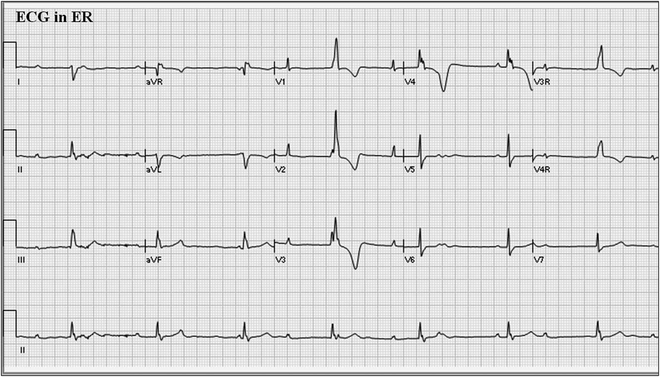
Figure 1 12-lead electrocardiogram (ECG) from patient at presentation to emergency department. ECG=electrocardiogram; ER=emergency room.
If the pacemaker programmer is not available, magnet application over the pacemaker may be helpful. Most pacemakers will respond to magnet application by pacing asynchronously at a fixed “magnet rate”. The magnet rate depends on the manufacturer and the battery status. That is, at battery “beginning of life”, the rate will be one value, at “elective replacement indicator” it will be another value, and at battery “end of life” it will be yet another value. If we apply a magnet and see asynchronous pacing with capture evident, then the lack of pacing spikes on the original ECG would be due to normal pacemaker function or to over-sensing. If we do not see any pacing spikes, then the problem would be lead insulation break or conductor fracture with premature current drain, battery depletion, or circuit malfunction. For this patient, magnet application in the emergency department did not show pacing spikes, suggestive of a hardware problem.
Once a programmer was applied to this patient’s pacemaker, it was found to be programmed to the VVIR mode, at a low rate of 60 bpm, upper sensor rate of 160 bpm, with bipolar pacing and sensing configuration. Telemetered diagnostics from the pacemaker helped determine the problem. In this case, there was a lead warning message, and the lead impedance trend showed a sudden jump in impedance from about 500 Ω (normal and physiologic) to >3000 Ω, suggestive of a lead fracture (Fig 2). The high rate counter also showed multiple episodes of high rate detections of 307–>400 bpm (Fig 3). The detailed information from these episodes showed intermittent lead noise and no true ventricular tachycardia episodes. Chest radiography showed that one of the legs of the bipolar lead was fractured (Fig 4). Thus, the lead had been showing signs of intermittent fracture (“make-break” episodes) with eventual complete fracture of one of the electrode legs, likely while the patient was playing basketball resulting in abrupt cessation of pacing. The patient’s sudden slower intrinsic rhythm likely was responsible for his brief syncopal episode.
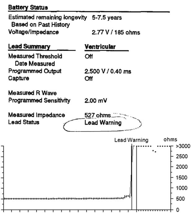
Figure 2 Pacemaker telemetry data from device interrogation.

Figure 3 Pacemaker counter showing high rate episode data. VHR=ventricular high rate.

Figure 4 Posteroanterior chest radiograph. The arrow points to the site of lead fracture which was on one of the electrode legs of the bipolar epicardial lead.
Threshold tests were performed after reprogramming the pacing and sensing configuration to unipolar, which was only possible in this case because the fractured lead component was the anode, and the measurements were acceptable (0.5 V 0.4 ms, R wave 15.68 mV, 468 Ω). Provocative manoeuvres were performed in this configuration to see whether one could unmask noise artefacts that may have caused over-sensing or loss of capture, but the findings were negative. Thus, the pacemaker was kept in unipolar mode. Ambulatory Holter monitoring for 24 hours did not show any loss of capture or sensing problem. From this testing, it was demonstrated that the fractured lead leg was the anodal electrode, and it was possible to retain function of this pacemaker system by reprogramming from bipolar to unipolar configuration. Given that this patient is not pacemaker dependent, this programming change was an acceptable solution.
Conclusion
Current pacemaker technology has a large variety of programming options to tailor individual patient needs. When pacemaker problems arise, a systematic approach is needed to troubleshoot the problem, and it may be possible to use programming adjustments to circumvent problems in order to retain a functioning pacemaker system.
Acknowledgements
None.
Financial Support
This research or review received no specific grant from any funding agency or from commercial or not-for-profit sectors.
Conflicts of Interest
None.
Ethical Standards
The authors assert that all referenced work contributing to this review complies with the ethical standards of biomedical or medicolegal investigation.


