


Introduction
Transmission zeros (TZs) are increasingly important for the high-performance bandpass filters (BPFs), since they improve the passband selectivity, enhance the stopband rejection, and help flatten the group delay without increasing the filter order. Some popular methods have been extensively studied to realize BPFs with the maximum number of TZs, such as cross-coupling (including source–load coupling) [Reference Cameron, Kudsia and Mansour1], 0° feeding structures [Reference Tsai, Lee and Tsai2], dual-mode ring resonators [Reference Feng3], transversal topologies [Reference Ohira, Kato and Ma4], E–M mixed coupling [Reference Wan and Li5], etc. However, the maximum number of TZs is theoretically limited at N for N-order BPFs. To break through this limitation, various techniques have been reported to achieve N + 1 or N + 2 TZs, such as three-path coupling [Reference Lu, Barker and Tang6], mixed source–load coupling [Reference Szydlowski, Lamecki and Mrozowski7], two-order filters with four resonators [Reference Wei8]. In general, they are only applicable to order-specified filters (e.g. [Reference Lu, Barker and Tang6] only for two-order filters) or need extra coupling structures, or their new TZ or TZs are much closer to the spurious band than the fundamental passband with little improvement for passband performance.
It is well known that harmonics exist in all resonant behaviors, but few filter designs have taken them into account or employed them for the BPF design (except for multimode resonators). In the present paper, we propose a new fully canonical coupling topology in which one λ/4 resonator provides a resonant node, while its first harmonic, as a non-resonating node (NRN), reacts with the passband and introduces one more TZ. Benefitting from such a coupling topology and node distribution technique, the N-order BPF response with N + 1 TZs is achieved where all TZs are close to the passband of the BPF and far away from the harmonic passband. Due to a λ/4 resonator acting as both a resonant node and an NRN, no additional circuit size is added when compared with the fully canonical filters. Additionally, the proposed approach is based on the generalized coupling matrix; therefore, it can be scaled to any frequency or bandwidth. In the following content, we use 1 GHz center frequency and 9% fractional bandwidth for demonstration.
Filter technique and TZ analysis
The design concept of our proposed technique is illustrated by a coupling topology. As presented in Fig. 1, a fully canonical BPF is formed by including the source–load coupling M SL, and the strongest coupling node of the topology not only behaves as a central coupling path for the passband but also provides an NRN. Therefore, the N-order response with an NRN can be achieved by an N-order filter layout, thus resulting in the total circuit size reduction. Without loss of generality, a λ/4 resonator and a λ/2 resonator are utilized for this design, and the λ/4 resonator is considered herein as the strongest coupling node.
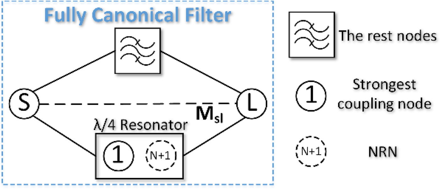
Fig. 1. The proposed coupling topology.
EM simulator HFSS and Rogers 5880 (h = 0.508 mm, ε r = 2.2, and tanδ = 0.0009) are employed to investigate the physical circuits. Fig. 2 presents the coupling matrices and the corresponding layout dimensions of two two-order filters. The coupling matrices are symmetrical “N + 2-order matrices” where M S1 = M 1L, M S2 = −M 2L, M S3 = M 3L, M SL = M LS represent the source/load–resonator and source–load couplings, and M 11, M 22, M 33 stand for the resonant frequency offsets of the resonators (including NRN). In the schematic layout (Fig. 2), the λ/4 resonator (red) provides the node 1 and node 3 (NRN), while the λ/2 resonator (blue) provides the node 2. As seen, the only difference between the two filters is M 22 for the coupling matrix with or without the dashed sections for the schematic layout. Fig. 3 presents the resultant responses of the coupling matrix and HFSS simulation, in which a good agreement can be observed when compared with each other. Closer scrutiny reveals that tuning the resonant frequency of the λ/2 resonator (adding the dashed sections and changing the value of M 22) can shift the passband and second TZ position, but has little influence on first and third TZs, which implies that the first and third TZs are introduced by the source–load coupling and λ/4 resonator. However, according to [Reference Cameron, Kudsia and Mansour1], two-order filter with source–load coupling can generate the maximum number of TZ equal to 2. Therefore, the new TZ (the third TZ) is due to the NRN and introduced by the λ/4 resonator. Note that, because of the proposed topology, the new TZ is far away from the harmonic passband (2f 0 and 3f 0) and very close to the passband. Fig. 4 presents the frequency response comparison with and without NRN by solving the coupling matrices. Apparently, the additional TZ is introduced due to use of the NRN.
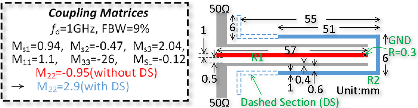
Fig. 2. Coupling matrices and physical dimensions of two-order filters with three TZs.
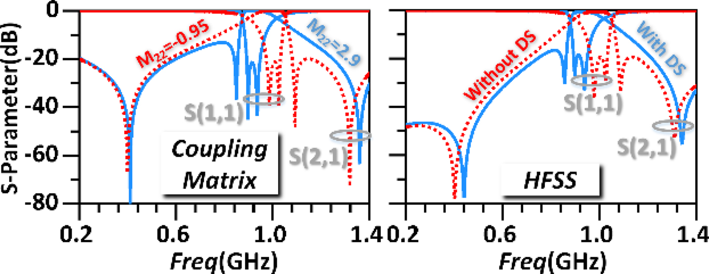
Fig. 3. Frequency responses of coupling matrices and HFSS simulations.
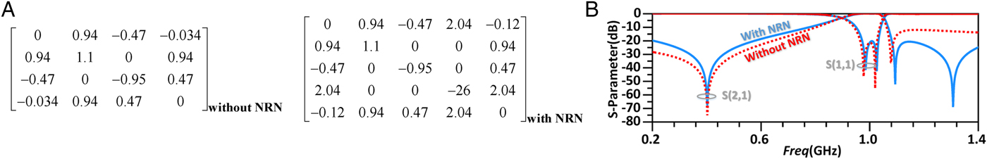
Fig. 4. Frequency response comparison of two-order filters with and without NRN and their associated coupling matrices.
High-order filters
The proposed technique can be applied to high-order filters. As the simple demonstrations, three-order and four-order filters with 1 GHz center frequency and 9% FBW are designed to produce four TZs and five TZs, as shown in Figs 5 and 6, respectively. To achieve fully canonical filters, the λ/4 and λ/2 resonators are alternately arranged with the frequency increasing, and the strongest coupling node (λ/4 resonators) is the center node (for odd-order filter) or one of the two center nodes (for even-order filter). Note here, the interdigital coupling sections are used in three-order filter structure to feed the second resonator. This is because the stronger capacitive coupling can be provided by the interdigital sections, which is used to meet the required capacitive coupling and avoid the very small gap width. Fig. 7 presents the response comparisons between the two-, three-, and four-order coupling matrices and HFSS simulations with three- and four-order coupling matrices. The two-order matrix has been given in Fig. 4. As seen in the response comparisons, good agreement and N + 1 TZs are obtained. Note that the coupling coefficients of the NRNs (with source or load) are extracted according to HFSS simulations because they are too far away from the passband and can not be accurately synthesized by the frequency-invariable synthesis [Reference Cameron, Kudsia and Mansour1]. The resonators are folded or split (λ/4 resonator) to reduce the total circuit size and simplify the design.
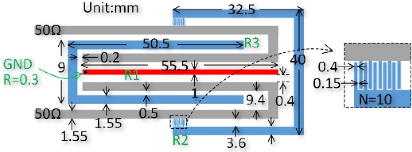
Fig. 5. Physical dimensions of three-order filters.
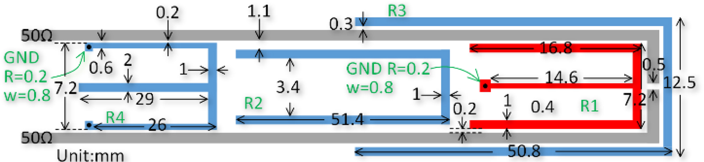
Fig. 6. Physical dimensions of four-order filters.
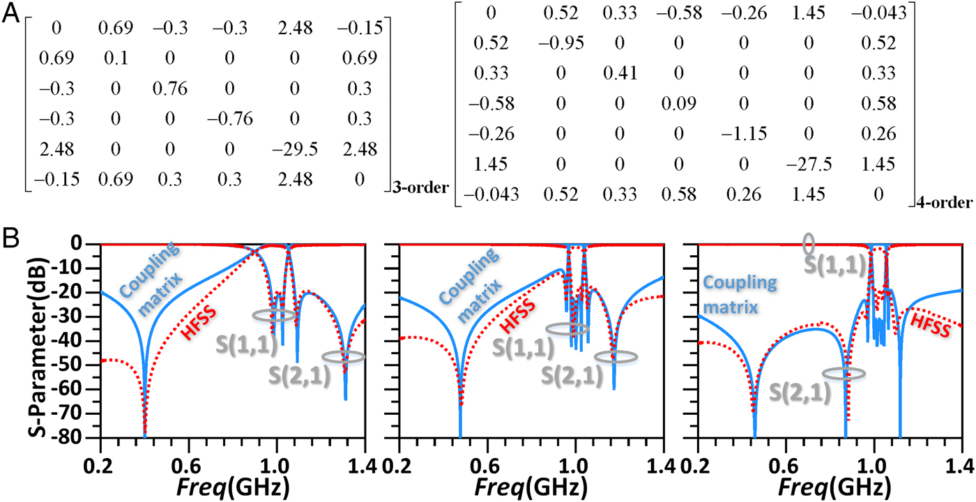
Fig. 7. Response comparisons between coupling matrices and HFSS simulations with their corresponding coupling matrices.
Measurement results
Three filters are fabricated on Rogers 5880 substrate and measured by National Instruments VNA for verification. Fig. 8 presents the measured responses of three demonstrative filters, which agree well with their corresponding HFSS simulations. As can be seen, two-, three-, and four-order filters provide two-, three-, and four-pole passbands, respectively, with all around 15 dB return loss. The insertion losses are 0.8, 1.45, and 2.1 dB at 1 GHz, and the 3 dB bandwidths are 110, 69, and 70 MHz, respectively. Three TZs for the two-order filter, four TZs for the three-order filter, and five TZs for the four-order filter are observable around the passband, and they have also located far away from the harmonic passbands and closer to the desired passbands, thus effectively improving the corresponding passband performance. Fig. 9 presents the simulated and measured four-order filter in the vicinity of the passband with the photographs of three example filters. As shown from the S 21 response, four TZs are very close to the passband, thus resulting in a highly selective elliptic response, while the minimum in-band return loss is kept larger than 14 dB.

Fig. 8. Response comparisons between measurement results and HFSS simulations.
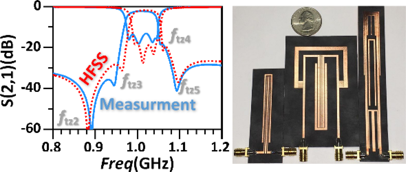
Fig. 9. Simulated and measured four-order filter S 21 in narrow band, and the photographs of three example filters.
Conclusion
The present paper has presented a possible solution to cope with the challenge that N-order filters can generate a maximum number of TZs no more than N. The design concept has been demonstrated by a coupling topology. The newly introduced TZ of a fully canonical two-order filter has been investigated by both the corresponding coupling matrix and HFSS simulation to validate the TZ production. Based on the proposed technique, the two-, three-, and four-order filters with three, four, and five TZs, respectively, have been designed and measured. The measurement results have experimentally confirmed the N + 1 TZ production technique.
 Di Lu was born in Yunnan province, China, in 1987. He received the B.S. degree in electronic engineering school from the Chengdu University of Information and Technology (CUIT), China, in 2013. He now is pursuing his Ph.D. in the University of Science and Technology of China (UESTC). Since October 2015, he has been a Visiting Student with the University of Virginia (UVA). His main research interests are design microwave filters, tunable filters, frequency multipliers, mixers, millimeter-wave circuits, and RF MEMS.
 Xiao-Hong Tang received the B.S. and Ph.D. degrees in electromagnetism and microwave technology in UESTC. Now he is a Professor in UESTC. He has authored more than 100 journal and conference papers. He was also the recipient of several national and provincial awards. His research interests include microwave and millimeter communication, computational electromagnetics, etc.
 N. Scott Barker received the B.S.E.E. degree from the University of Virginia, Charlottesville, VA, USA, in 1994, and the M.S.E.E. and Ph.D. degrees in electrical engineering from the University of Michigan at Ann Arbor, Ann Arbor, MI, USA, in 1996 and 1999, respectively. From 1999 to 2000, he was a Staff Scientist with the Naval Research Laboratory. In 2001, he joined the Charles L. Brown Department of Electrical and Computer Engineering, University of Virginia, where he is currently a Professor. He recently co-started the company Dominion Micro Probes Inc., Charlottesville, VA, USA, to develop the terahertz frequency wafer probe technology co-invented by his group at the University of Virginia. He has authored or coauthored over 60 publications. His research interests include applying microelectromechanical systems (MEMS) and micromachining techniques to the development of millimeter-wave and terahertz circuits and components. Professor Barker has served on the MTT-21 Technical Committee on RF-MEMS since 2000 and was the Committee Chair from 2008 to 2011. He has also served for many years on the IEEE Microwave Theory and Techniques Society (IEEE MTT-S) International Microwave Symposium (IMS) Technical Program Review Committee. In 2011, he served on the Steering Committee, IEEE MTT-S IMS, Baltimore, MD, USA. He was the Technical Program Committee (TPC) Vice-Chair for the 2014 IEEE MTT-S IMS, Tampa, FL, USA. He was an Associate Editor for IEEE Microwave and Wireless Components Letters (2008–2010). He is currently an Associate Editor for the IEEE Transactions on Microwave Theory and Techniques. He was the recipient of the Charles L. Brown Department of Electrical and Computer Engineering New Faculty Teaching Award (2006) and the Faculty Innovation Award (2004), the 2003 National Science Foundation (NSF) CAREER Award, the 2000 IEEE Microwave Prize, and First and Second Place in the Student Paper Competition, IEEE MTT-S IMS.


