


Introduction
The development of substrate integrated waveguide (SIW) components and systems is gaining increasing interest in both academic research and industrial applications [Reference Bozzi, Georgiadis and Wu1, Reference Wu, Bozzi and Fonseca2], thanks to their capability to combine simple design, easy fabrication, and unprecedented possibility to implement complete RF and microwave systems in a single dielectric substrate. Among all the classes of SIW components, filters have always attracted special attention, as they represent a key element in any wireless circuit and systems.
A variety of SIW filters have been proposed and implemented in the last two decades [Reference Chen and Wu3–Reference Chen and Wu5]: starting from simple inline filters [Reference Deslandes and Wu6, Reference Tang, Hong, Hao, Chen and Wu7], inspired by the corresponding topologies in classical waveguide technology, more sophisticated structures based on multilayer configurations have been proposed [Reference Chien, Shen, Huang, Wang and Wu8, Reference Chin, Chang, Chen, Guo, Wang and Che9].
Two major issues have inspired the investigation of novel SIW filter topologies in the past two decades: on the one hand, the need for more selective frequency responses, obtained through the use of transmission zeros located close to the passband. On the other hand, the overall footprint miniaturization, achieved by reducing the size of the cavity resonators that constitute the filters, while preserving a reasonable value of their quality factor.
The introduction of transmission zeros in the frequency response can be achieved in several ways: by introducing a coupling between non-adjacent cavities [Reference Cheng and Wu10], by adopting multi-mode cavity resonators [Reference Chen, Wu and Drolet11], and by using frequency-dependent couplings [Reference Szydlowski, Leszczynska and Mrozowski12–Reference Lee, Nam and Lee14].
The miniaturization of SIW cavities can be based on a number of different modified SIW structures. Folded SIW structures allow to implement compact transmission lines [Reference Grigoropoulos, Sanz-Izquierdo and Young15] and cavities [Reference Moro, Moscato, Bozzi and Perregrini16] folded around a metal septum, by adopting a dual-layer technology and reducing the footprint by a factor two. Half-mode SIW (HMSIW) structures exploit the virtual magnetic wall along a symmetry plane to remove half of SIW interconnects [Reference Hong, Liu, Wang, Lai, Tang, XX, YD, Zhang and Wu17] and cavities [Reference Delmonte, Silvestri, Bozzi and Perregrini18], thus obtaining a size reduction. The same concept can be applied twice, leading to quarter-mode SIW cavities [Reference Moscato, Tomassoni, Bozzi and Perregrini19, Reference Delmonte, Tomassoni, Perregrini and Bozzi20], which reduced the size by a factor 4. Other miniaturization techniques proposed in the literature are based on the use of cavities loaded with complementary split-ring resonators [Reference Dong, Yang and Itoh21, Reference Dong and Itoh22]. A thorough investigation of miniaturized SIW cavities and filters employing ramp-shaped slots was presented in [Reference Pourghorban Saghati, Pourghorban Saghati and Entesari23], leading to more than 90% miniaturization. The use of high-permittivity ceramic substrates (with relative permittivity up to 90) was presented in [Reference Le Coq, Rius, J-F, Quendo, Potelon, Estagerie, Moroni, Bonnet and El Mostrah24] with the aim to reduce the footprint of SIW filters.
This paper presents a review of some recent advances in the implementation of SIW filters, which combine improved out-of-band rejection based on transmission zeros and novel miniaturization strategies. More specifically, section “Introducing transmission zeros in SIW filters” presents an overview of classical approaches to introduce transmission zeros in SIW filters. Section “On the synthesis of extracted-pole filters” describes the technique for the synthesis of extracted-pole filters, whereas section “Extracted-pole filters in half-mode SIW technology” reports the implementation and experimental verification of extracted-pole filters in SIW technology. Finally, the use of pre-filters to improve the out-of-band frequency response of SIW filters is presented in section “Pre-filters integrated with SIW filters”, with numerical and experimental results. Conclusions are drawn in the last section.
Introducing transmission zeros in SIW filters
Since the SIW technology has been adopted for the realization of microwave filters, many solutions have been proposed for introducing transmission zeros in the response of these filters. In principle, the same solutions adopted for classical rectangular waveguide filters can also be used in SIW filters. However, the small thickness of the SIW waveguide makes some of these techniques unpractical or even impossible to use (for instance, those based on resonating irises or partial-height posts).
The simplest solution to get transmission zeros in SIW filters is based on the introduction of coupling between non-adjacent cavities. This technique has been widely investigated in the literature, together with solutions based on multi-mode and/or overmoded cavities [Reference Cheng and Wu10, Reference Chen, Wu and Drolet11, Reference Chen, Wu and Li25–Reference Sirci, Sánchez-Soriano, Martínez and Boria30]. However, such solutions have a common drawback, represented by the large size of the structure. Moreover, the synthesized routing schemes may require both positive and negative couplings, not always easily realizable with the usual SIW coupling structures [Reference Cheng and Wu10]. To this regard, the use of filter configurations with all couplings of the same type would make the SIW implementation much simpler and convenient.
More recently, SIW filters with inline topology and transmission zeros generated by frequency-dependent couplings have been proposed [Reference Macchiarella, Gentili, Delmonte, Silvestri, Tomassoni, Perregrini and Bozzi13, Reference Jedrzejewski, Szydlowski and Mrozowski31, Reference Liu, Zhou, Zhang and Lv32]. This solution, besides allowing the reduction of the overall filter size compared to classical cross-coupled topologies, has input and output ports on the opposite sides, thus reducing drastically the direct input-output feedthrough (that establishes the floor for the stopband rejection). However, it may be problematic to realize the required frequency dependence of the couplings, especially with transmission zeros close to the passband.
A topological solution featuring all couplings of the same sign (and nearly constant with frequency) is represented by the extracted-pole configuration [Reference Cameron, Kudsia and Mansour33], which becomes very convenient in fully canonical filters, when the maximum number of transmission zeros are requested for a given filter order. Another advantage of the extracted-pole topology relies in its quasi-inline configuration, whose advantages has been pointed out above.
Surprisingly, despite the aforementioned advantages, relatively few papers on SIW filters with extracted-pole topology have been published in the scientific literature [Reference Chen, Hong, Hao and Wu34]. Recently, two papers [Reference Macchiarella, Tomassoni, Massoni, Bozzi and Perregrini35, Reference Massoni, Delmonte, Macchiarella, Perregrini and Bozzi36] have proposed an original implementation of SIW filters in extracted-pole configuration, also presenting a compact implementation, obtained by means of HMSIW technology. This latter solution, in addition to reducing by a factor two the dimension of the resonators [Reference Lai, Fumeaux, Hong and Vahldieck37], allows the introduction of microstrip components (stubs) into the filter structure, with a further reduction of the overall size.
On the synthesis of extracted-pole filters
As for most microwave filters, the first step of the design consists of a lowpass prototype synthesis, exhibiting the required frequency response in the lowpass normalized frequency domain [Reference Macchiarella and Tamiazzo38]. This latter is defined by the well-known bandpass-to-lowpass frequency transformation [Reference Macchiarella and Tamiazzo38]: Ω = (f/f 0 − f 0/f)/Bn, where f 0 is the bandpass center frequency and Bn is the normalized bandwidth (passband width divided by f 0). Assuming a polynomial model for the filter, the elements of the scattering matrix can be expressed as follows:

where N is the filter order, ɛ and ɛR suitable real constants. Moreover, P(s), F(s), E(s) are monic polynomials generally referred to as characteristic polynomials; s = Σ + jΩ is the complex frequency variable. The roots of P(s) represent the assigned transmission zeros, those of F(s) are the reflection zeros and those of E(s) are the poles (the number N of poles is the filter order). The asterisk in (1) denotes the para-conjugate operator [Reference Cameron, Kudsia and Mansour33]. For the properties of this operator, if the reflection zeros are pure imaginary, F(s)* = F(s) and S22 = S11.
The characteristic polynomials can be evaluated once an approximating polynomial function of the desired response is assigned. The most usual one is represented by the Generalized Chebycheff characteristic, which features N imaginary reflection zeros determining an equi-ripple response in the passband for a set of assigned transmission zeros (zPk). These latter can be chosen in the whole complex plane but must be symmetric with respect to the imaginary axis (zPk = −zPk*). Various procedures are available in the literature for evaluating the characteristic polynomials producing the Generalized Chebycheff response for assigned filter specifications [Reference Cameron, Kudsia and Mansour33]. The filter specifications are represented by the filter order, the passband, the return loss in the passband, and the transmission zeros required to get the desired rejection in assigned stopbands. Regarding the constants ɛ and ɛR in (1), they depend on the return loss and are related to each other. When the number of transmission zeros (Nz) is lower than the number of poles (N), it has ɛR = 1. Conversely, for fully canonical filters (Nz = N) it results $\varepsilon _R = {\varepsilon / {\sqrt {\varepsilon ^2-1} }}$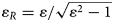 [Reference Cameron, Kudsia and Mansour33].
The characteristic polynomials introduced above produce a bandpass frequency characteristic in the de-normalized frequency domain f. However, a bandstop response can be obtained by exchanging polynomials P and F in (1) after their evaluation [Reference Amari and Rosenberg39]. Thereby, the original passband becomes the stopband characterized by N transmission zeros (the original roots of F(s)), while Nz reflection zeros are obtained in the passbands (the original stopbands). Note that the generated characteristic is fully canonical (number of transmission zeros equal to the filter order), with the number of reflection zeros lower than (or equal to) the number of poles. This type of bandstop characteristic is particularly convenient for realizing single-sided fully canonical filters, featuring only one passband and one stopband [Reference Macchiarella, Amari and Tamiazzo40]. In these filters, a high attenuation in the stopband can be obtained even with a relatively low order of the filter.
Once the characteristic polynomials have been evaluated, the low pass prototype can be synthesized. In case of extracted-pole filters, two basic topologies exist, whose features will be examined in the following.
Synthesis of the equivalent circuit
The synthesis of an equivalent circuit for extracted-pole filters is carried out in two steps. The first step is realized in the normalized frequency domain and, starting with the computed characteristic polynomials, produces a normalized low-pass prototype [Reference Amari and Macchiarella41]. In the second step, the low-pass prototype is transformed to get the circuit in the de-normalized frequency domain. This operation is carried out by exploiting the properties of the frequency transformation defined above and consists in replacing the capacitors (or inductors) in the low-pass circuit with shunt resonators (or series resonators) in the de-normalized circuit [Reference Cameron, Kudsia and Mansour33]. Further transformations can eventually be applied to the resulting circuit if specific features are required in the final topology. In the following, two possible topologies of the synthesized equivalent circuit will be presented, that are suitable for representing extracted-pole filters implemented in SIW technology.
Topology 1
The equivalent circuit is shown in Fig. 1. Note that an equivalent (dual) representation can also be used by replacing the shunt-connected parallel (series) resonators with series-connected series (parallel) resonators.

Fig. 1. (a) Synthesized equivalent circuit of extracted-pole filter (Topology 1). The horizontal elements represent transmission lines defined by the characteristic admittance (Yck ,k+1) and by the electrical length at frequency f 0 (ϕk ,k+1. (b) The shunt admittance Yk can be either a shunt resonator (pole extraction) or a series resonator (zero extraction). The equivalent slope parameter and the resonance frequency characterize these elements.
Note that, in general, all characteristic admittances of the transmission lines can be assigned to an arbitrary value (e.g. that of external loads Y 0) except one [Reference Macchiarella and Tamiazzo42]. However, in the case there is at least one reflection zero at infinite, all characteristic impedances can be assigned equal to Y 0, with a noticeable simplification of the filter implementation. This happens with the stopband characteristic mentioned before (obtained by exchanging P and F polynomials), assigning the number of reflection zeros (roots of P(s) in the original characteristic) lower than the filter order N. Note that, being the filter fully canonical, all admittances Yk in Fig. 1 are realized by series resonators (resonating at the frequencies of the transmission zeros).
Topology 2
The equivalent circuit in this case is shown in Fig. 2. As for the previous topology, the dual representation is obtained by replacing the shunt-connected admittances with series-connected impedances with the dual topology.

Fig. 2. (a) Synthesized equivalent circuit of extracted-pole filter (Topology 2). The blocks connecting the admittances Yk represent admittance inverters with parameter Jk ,k+1. (b) Circuit representation of the possible admittances Yk (the element in parallel to the series resonator is a frequency-invariant susceptance). The shunt resonator (upper circuit) extracts a pole while the bottom circuit extracts a pole-zero pair.
This circuit also exhibits N degrees of freedom which allow, for instance, to assign all the inverters parameters (except one) or all the equivalent slope parameters of the shunt-connected admittances [Reference Macchiarella and Tamiazzo42]. To this purpose, the generalized coupling coefficients introduced in [Reference Macchiarella43] can be advantageously employed.
Extracted-pole filters in half-mode SIW technology
HMSIW technology [Reference Lai, Fumeaux, Hong and Vahldieck37] represents an alternative to the classical SIW waveguide operating on TE10 mode, with half of the original structure, assuming a virtual magnetic wall along the E-plane of the SIW (Fig. 3) not affected by this operation.

Fig. 3. Derivation of the HMSIW from the SIW. The figures refer to the top view of both waveguides. The top metallization of the SIW is removed starting from the trace of the E-plane. Assuming the magnetic wall along this plane not affected by the metal removing, the two structures are equivalent as far as the propagation of TE10 mode is concerned. Note that the width a/2 of the equivalent HMSIW waveguide does not coincide exactly with the physical width a’/2 shown in the figure (formulas relating a and a’ are reported in [Reference Lai, Fumeaux, Hong and Vahldieck37]).
Although the equivalence depicted in Fig. 3 holds only in a first approximation, the HMSIW, other than reducing the overall size, also allows to connect components along the E-plane of the equivalent waveguide. This is very convenient in filters realization because microstrip components can be used, widening noticeably the class of implementable coupling structures.
Fully canonical single-sided filters
The design of fully canonical extracted-pole filters in HMSIW technology, with the topology 1 described above, was proposed for the first time in [Reference Macchiarella, Tomassoni, Massoni, Bozzi and Perregrini35]. The frequency characteristic is bandstop single-sided, with the number of reflection zeros lower than the number of poles. All the characteristic admittances Ycq,q+ 1 in Fig. 1 can then be assigned equal to the reference impedance Y 0 = Y HMSIW that represents the characteristic admittance of the equivalent HMSIW waveguide. The equivalent circuit of the filter is composed by a cascade of waveguide sections with characteristic admittance Y HMSIW and shunt-connected series resonators. The characteristic admittance Y HMSIW is obtained by dividing that of the rectangular waveguide by two, assuming the power-voltage definition:

where $Y_W = {{\sqrt {\varepsilon _r} } / {377}}$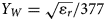 is the intrinsic admittance of the dielectric medium filling the waveguide (relative dielectric constant ɛ r), fc represents the cutoff frequency of TE10 mode, a/2 and b are the equivalent width and height of the waveguide, respectively. Note that, with this definition of characteristic admittance, the voltage along the lines in the equivalent circuit of the filter corresponds to the physical voltage along the open boundary of the HMSIW, just where the series resonators are connected. These latter are in fact implemented by open circuited microstrip stubs, whose length is a quarter wavelength at the frequencies of the transmission zeros. The characteristic impedance of the k-th stub (ZS,k) is related to slope parameter of the k-th resonator (Xeq,k) as:

Note that the values of Xeq,k, resulting from the synthesis, determine the impedances ZS,k, that must be realizable as microstrip lines on the assigned substrate. This poses a strong condition on the feasibility of the filter with the assigned electrical requirements and dielectric substrate. In some cases, it may be necessary to increase the bandwidth of pass- and/or stop-band even noticeably to have this condition satisfied.
The first design example reported in [Reference Macchiarella, Tomassoni, Massoni, Bozzi and Perregrini35] is a single-sided stopband filter of order 2, with 2 transmission zeros and 1 reflection zero. As for electrical requirements we have a passband at 6.64–7 GHz with return loss of 20 dB, and a stopband at 9.09–9.7 GHz, with rejection of 30 dB. The substrate used for the filter fabrication has a thickness b = 0.508 mm and a relative dielectric constant ɛ r = 2.2.
By imposing the reflection zero at 6.85 GHz, the synthesized characteristic polynomials determine the transmission zeros at 9.17 and 9.597 GHz. After de-normalizing the lowpass prototype, the equivalent circuit of the filter in Fig. 4 is obtained (where Z HMSIW = 1/Y HMSIW is the characteristic impedance of HMSIW waveguide).

Fig. 4. (a) Synthesized equivalent circuit of the filter, with ZS ,1 = 124.5 Ω, ZS ,2 = 105.8 Ω, ϕ 12=74.2° (at f 0 = 6.9 GHz). ZHMSIW is the characteristic impedance of the HMSIW waveguide evaluated at f 0 (see the text). The electrical length of the stubs (90°) is assumed at the frequencies of the transmission zeros. (b) Photograph of the manufactured HMSIW filter (from [Reference Macchiarella, Tomassoni, Massoni, Bozzi and Perregrini35]).
The equivalent HMSIW waveguide is dimensioned by assigning a/2 = 9.6 mm (b and ɛ r are those of the substrate). Z HMSIW = 1/Y HMSIW is computed through (2) at f 0 = 6.9 GHz (with Z HMSIW = 41.53 Ω). Note that the electrical length ϕ 12 at f 0 and the characteristic impedances of the stubs (whose electrical length is equal to 90° at the transmission zeros frequencies) have been slightly changed with respect the synthesized values to account for the frequency dispersion of the HMSIW waveguide. The final dimensions have been optimized by means of full wave simulation (HFSS) obtaining the following result: for the HMSIW, width a’/2 = 9.2 mm and length L 12 = 8.55 mm; for the stub 1, width = 0.4 mm and length = 5.6 mm; for the stub 2, width = 0.7 mm and length = 5 mm. The fabricated prototype (Fig. 4(b)) includes the transitions to input/output 50 Ω microstrip lines. Figure 5 shows the frequency response of the filter, where measurements are compared to the full-wave simulation from HFSS and from the equivalent circuit of the filter (Fig. 4(a)): a good agreement can be observed.

Fig. 5. Measured and simulated (HFSS) responses of the 2-pole filter (from [Reference Macchiarella, Tomassoni, Massoni, Bozzi and Perregrini35]). The response from the equivalent circuit (Fig. 4a) is also reported.
An example of higher order single-sided filter is also reported in [Reference Macchiarella, Tomassoni, Massoni, Bozzi and Perregrini35]. It exhibits of a fully canonical stopband characteristic with 4 transmission zeros and 3 reflection zeros. The following specifications have been assumed for the design: the passband is 11–12.5 GHz, with a return loss of 20 dB, and the stopband is 14–15 GHz with a rejection larger than 40 dB. The same substrate of the previous example has been used (b = 0.508 mm, ɛ r = 2.2).
The design has been carried out following the same procedure outlined for the previous filter. Figure 6(a) shows the photograph of the manufactured protype, while the measured response is shown in Fig. 6(b), compared with the ones obtained from full-wave simulation (HFSS) and equivalent circuit response.

Fig. 6. HMSIW filter of order 4: (a) photograph of the prototype; (b) simulated (HFSS & equivalent circuit) and measured frequency response (from [Reference Macchiarella, Tomassoni, Massoni, Bozzi and Perregrini35]).
From Fig. 6(b) it can be observed that the synthesized stopband is much larger than the requirements. This was necessary to obtain realizable values for the characteristic impedances of the microstrip stubs. Moreover, the measured response in the stopband is noticeable different with respect the ideal characteristic (although the required rejection is about satisfied). This is likely due to the coupling between the stubs, whose separation is relatively small. The interactions between higher order modes excited at the stubs junctions may also contribute to the disappearance of the rejection peaks. In any case, the concept considered here (i.e. the design of extracted-pole fully canonical HMSIW filters) has been satisfactorily validated.
Passband filters with one transmission zero close to the passband
Another solution for realizing HMSIW extracted-pole filters was introduced in [Reference Massoni, Delmonte, Macchiarella, Perregrini and Bozzi36], which is convenient when the assigned transmission zeros are relatively close to the passband. In this case, the topology 2 is selected for representing the filter equivalent circuit, but the dual representation is adopted. To illustrate the design procedure, the following electrical requirements are assumed: the passband is 4.335–4.570 GHz, the return loss is 20 dB, the filter order (number of poles) is 3, and the transmission zero is at 4.919 GHz.
The design starts with the synthesis of the lowpass prototype [Reference Amari and Macchiarella41], followed by the evaluation of the generalized coupling coefficients (GCC) [Reference Macchiarella43]. Figure 7(a) shows the routing scheme of the filter with the computed coefficients and resonating frequencies.
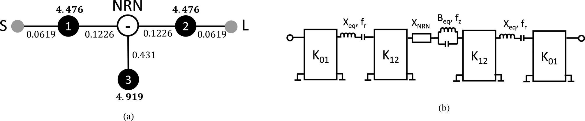
Fig. 7. Synthesized extracted-pole filter. (a) Routing scheme with the GCC (plain numbers) and resonating frequencies (bold numbers). Black circles are the resonant nodes, white circle is the non-resonating node, lines represent ideal inverters. Note that the NRN must be negative (TZ below the passband). (b) De-normalized (bandpass) equivalent circuit (series representation).
From the routing scheme, the equivalent circuit of the de-normalized bandpass filter can be derived (note that Fig. 7(b) shows the dual of the general scheme reported in Fig. 2(a)). Exploiting the definition of GCC and assuming that the series resonators are implemented with waveguide section half wavelength long at fr, the following relations holds (all quantities normalized to the impedance of the equivalent HMSIW waveguide):

Using the equivalence depicted in Fig. 8(a), the equivalent circuit of the filter is transformed as in Fig. 8(b).

Fig. 8. (a) Transformation of series-connected pole-zero block into a shunt-connected block. (b) Equivalent circuit of the filter after the pole-zero block replacement.
Replacing the expression of xNRN and beq derived from Fig. 8(a) into (4) we get the expressions for the evaluation of the equivalent circuit parameters in Fig. 8(b):

The dielectric substrate used for the physical implementation of the filter is characterized by b = 0.508 mm and ɛ r = 2.2. Assuming a/2 = 18.6 mm, the length of the equivalent HMSIW resonators is given by: Lr = λ r/2 = 28.44 mm. The terminal inverters (K 01,norm) are included in the transition from HMSIW to microstrip, where 50 Ω terminations are assumed. The block inside the dashes square in Fig. 8(b) extracts the pole-zero pair producing a transmission zero at 4.919 GHz and a reflection zero at 4.483 GHz, with the normalized slope parameters (xeq,s) equal to the value reported in (5). Such a block has been implemented in [Reference Massoni, Delmonte, Macchiarella, Perregrini and Bozzi36] by means of a coupling iris between the two HMSIW cavities and a microstrip stub connected to the open wall of the HMSIW at the iris section. Note that the actual length of the cavities has been suitably corrected to account for the iris and microstrip loading effect. The overall filter configuration, including the transition from microstrip to HMSIW, is shown in Fig. 9(a). Note that all the geometrical dimensions of the filter has been adjusted by means of HFSS to correct the approximations due to the equivalent waveguide representation of the HMSIW components during the initial dimensioning.

Fig. 9. (a) Manufactured prototype of extracted-pole filter. (b) Measured response of the fabricated filter (solid line) compared to full wave simulated response (HFSS) (from [Reference Massoni, Delmonte, Macchiarella, Perregrini and Bozzi36]).
Figure 9(b) shows the measured response of the fabricated prototype, compared to the full-wave HFSS simulation. The satisfactory agreement between the two set of curves validates the design procedure of also this type of extracted-pole HMSIW filter.
Concluding this section, we want to observe that the solutions here recalled are based on hybrid implementation (microstrip and SIW). This mixed approach requires taking into account the differences in Q factor that characterize these technologies. A convenient choice (adopted when possible in the mentioned solutions) is to realize the resonators with a high-Q implementation (SIW) and the coupling structures with low-Q microstrip elements.
Pre-filters integrated with SIW filters
The filter size reduction is very important as filters are among the bulkiest components in modern transceivers. Several approaches can be used for this purpose. In this case, the size reduction is not directly obtained by reducing the filter size, but by modifying its out-of-band filter response, to avoid the use of bulky low-pass filters often exploited for removing spurious frequencies. Solutions in this direction are proposed, for microstrip technology, in [Reference Marín, Martínez and Boria44, Reference Marín, Martínez, Valero and Boria45].
For SIW filters, the basic idea has been introduced in [Reference Tomassoni, Delmonte, Macchiarella, Bozzi and Perregrini46] and it consists in adding to the band-pass filter a sort of pre-filter. In contrast to the technique that exploits the lowpass, in this case filter and pre-filter need to be designed together, as they are in practice a single filter. Indeed, a separated design of filter and pre-filter leads to a completely unmatched response when they are cascaded.
To understand the basic principle, an example with a filter in SIW technology is presented. Figure 10 shows the scheme of a regular third-order inductive iris SIW filter operating at 4 GHz with a fractional bandwidth of 2.9% together with its wideband response [Reference Tomassoni, Delmonte, Macchiarella, Bozzi and Perregrini46]. In this case, the upper stopband is very limited because of a parasitic band appearing around 6 GHz. Parasitic bands are due to the higher-order modes of SIW cavities and iris resonances. In order to obtain a larger stop band, it would be convenient to use a different resonator technology, a good candidate being the quarter wave microstrip resonator obtained by short-circuiting a microstrip at one of its ends. By using such resonators instead of SIW cavities, responses with much larger stopbands can be obtained; however, this is paid in terms of in-band insertion loss (IL) because of the lower quality factor of the microstrip resonator. As an example, considering a Q-factor of 300 for SIW cavities and a Q-factor of 80 for microstrip resonators, the in-band IL in the considered 3-pole filter is 1.7 dB when the filter is realized with SIW cavities, and 6.2 dB when the same filter is realized with microstrip resonators. For several applications, an IL of 6.2 dB is unacceptable.

Fig. 10. Regular SIW filter: (a) geometry of the filter; (b) simulated and measured frequency response (from [Reference Tomassoni, Delmonte, Macchiarella, Bozzi and Perregrini46]).
The idea is then to use the two kinds of resonators together to take advantage of the relatively high Q-factor of the SIW cavities and the good out of band performance of the microstrip resonator.
According to Fig. 10, the implementation of the filter consists in adding two microstrip resonators at the input of the 3-pole filter of Fig. 10 so that to transform the 3-pole filter into a 5-pole filter [Reference Tomassoni, Delmonte, Macchiarella, Bozzi and Perregrini46]. In order to minimize losses related to the two low Q-factor microstrip resonators, strong couplings are exploited. Indeed, losses strongly depend on resonator couplings: the larger the couplings, the lower the losses. According to Fig. 11(a), by indicating the additional microstrip resonators with the numbers 1 and 2, this leads to choosing coupling coefficients MS1, M12 very large. In order to synthesize a proper response, it is then possible to select couplings M23, M34, M45, M5L so that the in-band behavior of the filter is quite similar to that of the 3-pole original filter [Reference Tomassoni, Delmonte, Macchiarella, Bozzi and Perregrini46]. This means that the filter working together with the prefilter is different from that of Fig. 10(a).
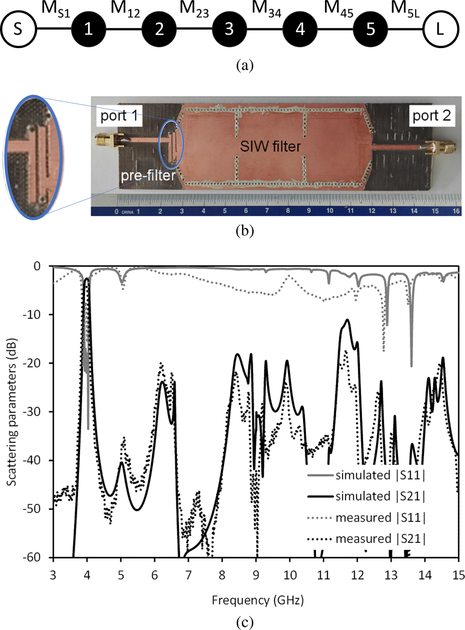
Fig. 11. SIW filter with prefilter: (a) filter routing scheme; (b) photograph of the prototype; (c) simulated and measured frequency response (from [Reference Tomassoni, Delmonte, Macchiarella, Bozzi and Perregrini46]).
After the synthesis, the filter has been realized in a mixed microstrip/SIW technology [Reference Tomassoni, Delmonte, Macchiarella, Bozzi and Perregrini46]. The photo of the manufactured filter is shown in Fig. 11(b). As can be seen the prefilter size is very small with respect to the SIW cavity filter and does not significantly increase the size of the overall filtering structure. The comparison between measured and simulated response is shown in Fig. 11(c).
As can be seen by comparing this response to that of Fig. 10(b), a noticeable improvement of the out-of-band performance has been obtained. This has been paid in terms of a moderate increase of the IL, that passed from the simulated value of 2.1 dB of the original 3-pole filter in Fig. 10 to the simulated value of 2.5 dB of the filter plus prefilter configuration (that become 3.9 dB in the measured prototype). In any case, the IL value of 2.5 dB is much better than that of a 3-pole filter made of solely microstrip resonators (with IL of 6.2 dB).
Conclusion
The implementation of compact SIW filters with the frequency response improved by the introduction of transmission zeros has been discussed in this paper. After an overview on the different solutions available for introducing transmission zeros, the synthesis of extracted pole filters has been briefly outlined. Subsequently, several compact filters, based on HMSIW structures, have been described. In these filters, the transmission zeros are introduced through the use of extracted poles as well as by a pole-zero block, and in both cases the effect is obtained by connecting microstrip stubs to the open boundary of the HMSIW. Finally, another class of filters has been presented, based on the introduction of a compact pre-filter in microstrip technology: this pre-filter allows improving the out-of-band rejection of classical SIW filters, without practically degrading the insertion loss performance.
 Giuseppe Macchiarella (M’90-SM’06-F15) is currently professor of microwave engineering with the Department of Electronic, Information and Bioengineering, Politecnico di Milano, Italy. Currently his activities are mainly focused on the development of new techniques for the synthesis of microwave filters and multiplexers. Prof. Macchiarella is fellow of IEEE and authored or co-authored more than 170 papers on journals and conferences proceedings. He has been responsible of several contracts and collaborations with various companies operating in the microwave industry. He has been chair of IEEE Technical Committee MTT-5 (Filters and passive Components). He is serving since several years in the Technical Program Committee of IEEE International Microwave Symposium and European Microwave Conference.
 Cristiano Tomassoni was born in Spoleto, Italy. He received the Ph.D. degree in electronics engineering from the University of Perugia, Perugia, Italy, 1999. His main area of research concerns the modeling and design of waveguide devices and antennas. His research interests also include the development of miniaturized filters, reconfigurable filters, dielectric filters, SIW filters, and 3D printed filters. Cristiano Tomassoni is an associate editor of the IEEE Transactions on Microwave Theory and Techniques and a member of the MTT-5 Filters and Passive Components Technical Committee. He received the Best Paper Award (Second Place) at NEMO 2018 and the Best Paper Award (first place) at the 15th Mediterranean Microwave Symposium (MMS2015). He was the recipient of the 2012 Microwave Prize presented by the IEEE MTT Society.
 Maurizio Bozzi received his Ph.D. from the University of Pavia in 2000. He held research positions with various universities, including Technische Universität Darmstadt, Germany, Universitat de Valencia, Spain, and École Polytechnique de Montréal, Canada. In 2002, he joined the University of Pavia, where he is currently a full professor. He was also a guest professor at Tianjin University, China, and Gdansk University of Technology, Poland. His main research interests concern the substrate integrated waveguide technology and the use of novel materials and fabrication technologies for microwave circuits. Prof. Bozzi is an elected member of the Administrative Committee of the IEEE MTT Society and the current Treasurer. He is also a track editor of the IEEE Transactions on Microwave Theory and Techniques. He was the general chair of the various international conferences, including the IEEE IMWS-AMP 2017, IEEE NEMO 2014, and IEEE IMWS 2011.


