


1. Introduction
Droplets impacting solids are a ubiquitous phenomenon in nature and industrial processes (Bixler & Bhushan Reference Bixler and Bhushan2014; Lu et al. Reference Lu, Sathasivam, Song, Crik, Carmalt and Parkin2015; Josserand & Thoroddsen Reference Josserand and Thoroddsen2016; Qi & Weisensee Reference Qi and Weisensee2020). One of the important factors affecting the dynamic behaviour of droplets is the surface wettability. Generally, droplets tend to adhere to hydrophilic surfaces and rebound from hydrophobic surfaces (Li et al. Reference Li, Kong, Ma, Zang, Guan and Ren2017; Liu, Zhang & Min Reference Liu, Zhang and Min2019a; Xie et al. Reference Xie, Ding, Ingham, Ma and Pourkashanian2020). Because the forces exerted on various wettability surfaces are different, the use of heterogeneous surfaces can generate richer droplet motion forms, which include droplet splitting using a hydrophilic substrate decorated with hydrophobic patterns (Song et al. Reference Song, Song, Hu, Du and Zhou2015) and achieving droplet rebound with deflection or gyration by adopting a hydrophobic substrate decorated with hydrophilic patterns (Li et al. Reference Li, Fang, Li, Yang, Li, Li, Feng and Song2019). These studies are of great significance for droplet control in engineering applications.
Due to the wide range of applications in self-cleaning and anti-icing (Lv et al. Reference Lv, Song, Jiang and Wang2014; Lu et al. Reference Lu, Sathasivam, Song, Crik, Carmalt and Parkin2015), droplet rebound with lateral motion has received considerable attention in recent decades. Schutzius et al. (Reference Schutzius, Graeber, Elsharkawy, Oreluk and Megaridis2014) studied both a hydrophobic substrate decorated with hydrophilic patterns and a hydrophilic substrate coated with a superhydrophobic line, and they showed directional transport when a droplet impacted a hydrophobic substrate with a hydrophilic stripe. Zhao et al. (Reference Zhao, Li, Hu, Li, Cai, Huang, Su, Li, Li and Song2019) and Chu et al. (Reference Chu, Luo, Hao, Zhang, Wu and Wen2020) further investigated the effect of impact position on the lateral transport distance. Russo et al. (Reference Russo, Icardi, Elsharkawy, Ceglia, Asinari and Megaridis2020) and Zhang, Wu & Lin (Reference Zhang, Wu and Lin2021) also observed similar phenomena in numerical simulations, and the effect of multiple parameters on the droplet motion was systematically investigated. The dominating factor of droplet lateral motion is the presence of asymmetric forces, which are induced by a hydrophilic stripe arranged on one side of the impact point (Zhao et al. Reference Zhao, Li, Hu, Li, Cai, Huang, Su, Li, Li and Song2019, Reference Zhang, Wu and Lin2021). Thus far, the dynamic mechanism of droplet rebound with lateral motion is clear, and precise prediction and control can also be achieved.
Because asymmetric forces can be used to manipulate a droplet, can its counterforces actuate the solid? This topic has recently aroused great interest in the scientific community, and there have been some studies trying to harvest energy from falling droplets in the field of power generation. On the one hand, the normal impact force can cause oscillation of a cantilever-style substrate, which can be applied to a piezoelectric device (Weisensee et al. Reference Weisensee, Tian, Miljkovic and King2016; Jellard et al. Reference Jellard, Pu, Chen, Yao and White2019; Xu et al. Reference Xu2020). The experimental results of Zhao et al. (Reference Zhao, Li, Li, Fang, Cai, Li, Feng and Song2021) demonstrated that breaking the symmetry of a droplet impact dynamics using patterned-wettability surfaces can suppress the Plateau–Rayleigh instability during droplet rebound and improve the energy collection efficiency of a piezoelectric device. On the other hand, some researchers have attempted to convert the kinetic energy of droplets into the tangential direction to drive a solid. Li et al. (Reference Li, Fang, Li, Yang, Li, Li, Feng and Song2019) reported the rotation of a thin solid sheet with heterogeneous surface patterns under droplet impact. Zhao et al. (Reference Zhao, Li, Hu, Li, Cai, Huang, Su, Li, Li and Song2019) found that a falling droplet can drive a floating microboat with patterned surfaces. Collecting energy from the natural environment, such as raindrops, to induce solid motion and further use for power generation is significant but usually neglected. This approach can drive and sustain electrical systems with low power consumption, such as wireless sensor networks. Especially in remote areas, this energy source is very useful for the independent operation of electrical/sensor systems.
In the abovementioned studies of droplets impacting a heterogeneous wettability surface, the main focus was on droplet manipulation, while only limited preliminary studies have been made on solid motion. Therefore, there are still some unsolved problems due to the complexity of the droplet–solid interaction. First, previous experimental observations were performed to validate the idea that the counterforces could actuate the solid; thus, the analysis of the dynamic mechanism of solid motion is inadequate. Second, because systematic investigations on the effect of impact conditions on solid motion are lacking, controllable solid motion has not yet been extensively investigated. Finally, to realize the collection and utilization of energy, the subsequent solid motion (such as rotation or reciprocation) needs to be further explored.
In this work, droplet-driven solid motion is simulated by adopting the validated diffuse interface method. The evolution of the lateral motion of a movable solid with a heterogeneous wettability surface and two linear dampers is presented. After preliminarily checking the effects of the solid mass and damping coefficient of linear dampers, the variations in lateral force and instantaneous displacement distance with time are analysed. Then, the effects of the impact parameters on the solid motion are studied, including the initial droplet diameter, impact velocity and offset distance between the impact point and hydrophilic stripe. On this basis, reciprocating solid motion under successive droplet impacts is further investigated.
2. Problem description and methodology
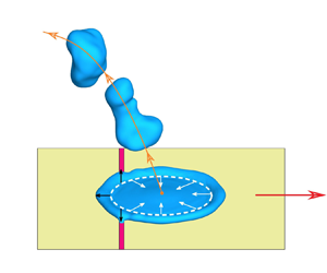
The scheme of a droplet impacting a movable solid is illustrated in figure 1. The solid surface is covered by a hydrophobic substrate and a hydrophilic stripe. To study the dynamic behaviour of droplet-driven solids, the solid is set to be laterally movable, while translation in other directions and rotation are restricted. The solid motion is restrained by two linear dampers, which provide a reactionary force that is proportional to the velocity. Similar to previous studies (Chu et al. Reference Chu, Luo, Hao, Zhang, Wu and Wen2020; Russo et al. Reference Russo, Icardi, Elsharkawy, Ceglia, Asinari and Megaridis2020; Zhang et al. Reference Zhang, Wu and Lin2021), the spherical droplet with diameter D 0 is initially located extremely close to the solid, and it impacts the solid surface with a predetermined impact velocity U 0. Water droplets and air are used as the working fluids. In addition, the dimensionless parameter, i.e. Weber number, is defined as  $We = {\rho _l}{D_0}U_0^2/\sigma$, where
  ${\rho _l}$ and
  $\sigma$ are the density and surface tension coefficient of the water droplet, respectively. The offset distance between the impact point and the hydrophilic stripe is denoted as a (as shown in figure 1b).

Figure 1. (a) Droplet impacting a movable solid with a heterogeneous surface. (b) Two-dimensional schematic of the droplet-driven solid system. The hydrophobic substrate (yellow) is decorated with a hydrophilic stripe (red), and the solid motion is restrained by two linear dampers.
The droplet–solid interaction in this work is considered as an incompressible and isothermal multiphase flow problem. The interface is captured by an improved Cahn–Hilliard model (Zhang, Wu & Lin Reference Zhang, Wu and Lin2020), which is implemented in the OpenFOAM framework (Jasak Reference Jasak1996):
 \begin{equation}\frac{{\partial C}}{{\partial t}}\textrm{ + }\boldsymbol{\nabla }\boldsymbol{\cdot }(\boldsymbol{u}C)\textrm{ + }\boldsymbol{\nabla }\boldsymbol{\cdot }\left[ {\gamma C(1 - C)\frac{{\boldsymbol{\nabla }C}}{{|\boldsymbol{\nabla }C|}}} \right]\textrm{ = }M{\nabla ^2}\phi ,\end{equation}
where C is the order parameter in the range of [0, 1] and u is the fluid velocity. In this model, the interface correction term (third term on the left-hand side of (2.1)) is introduced into the original Cahn–Hilliard equation to suppress the phenomenon of interface dispersion. As a result, the interface can be kept thin and sharp, which is beneficial for improving the reliability of numerical simulations. Here,  $\gamma$ is an adaptive parameter used to control the magnitude of the interface correction, which is strongly correlated with the interface dispersion. The additional term is taken into account only in the diffuse layer, and it works normal to the interfaces, i.e. in the direction
  $\boldsymbol{\nabla }C/|\boldsymbol{\nabla }C|$. Parameter M is the mobility and
  $\phi$ denotes the chemical potential. Based on the free energy density model (van der Waals Reference van der Waals1979), the chemical potential is defined as
  $\phi = (\alpha \sigma /\textrm{2}\varepsilon )C(C - 1)(2C - 1) - \alpha \sigma \varepsilon \Delta C$. Here,
  $\varepsilon$ measures the interface thickness and
  $\alpha$ is a positive constant, which is equal to
  $6\sqrt 2$ (Kim Reference Kim2005; Ding, Spelt & Shu Reference Ding, Spelt and Shu2007). The equilibrium function of the one-dimensional interface profile C can be written as
 \begin{equation}C(z) = \frac{1}{2}\left[ {1 + \tanh \left( {\frac{z}{{2\sqrt 2 \varepsilon }}} \right)} \right],\end{equation}
where z is the signed normal distance to the interface.
The flow field is obtained by solving the Navier–Stokes equations, which are written as
 \begin{gather}\boldsymbol{\nabla }\boldsymbol{\cdot }\boldsymbol{u} = 0,\end{gather}
 \begin{gather}\frac{{\partial (\rho \boldsymbol{u})}}{{\partial t}} + \boldsymbol{\nabla }\boldsymbol{\cdot }(\rho \boldsymbol{uu}) ={-} \boldsymbol{\nabla }p + \boldsymbol{\nabla }[\mu \cdot (\boldsymbol{\nabla }\boldsymbol{u} + {(\boldsymbol{\nabla }\boldsymbol{u})^T})] + \rho \boldsymbol{g} + {\boldsymbol{F}_\sigma },\end{gather}
where g is the gravitational acceleration,  ${\boldsymbol{F}_\sigma } ={-} C\boldsymbol{\nabla }\phi$ is the surface tension force and
  $\rho$ and
  $\mu$ are the density and dynamic viscosity, respectively, which depend on the order parameter C:
 \begin{equation}\rho = {\rho _l}C + {\rho _g}(1 - C),\quad \mu = {\mu _l}C + {\mu _g}(1 - C),\end{equation}
where the subscripts ‘l’ and ‘g’ denote water and air, respectively.
When the two-phase interface interacts with the solid surface, the unit normal vector of the interface n should be modified by the contact angle  ${\theta _d}$, and it is expressed as
 \begin{equation}\boldsymbol{n = }\frac{{\boldsymbol{\nabla }C}}{{|\boldsymbol{\nabla }C|}}\boldsymbol{= }{\boldsymbol{n}_w}\cos {\theta _\textrm{d}} + {\boldsymbol{t}_w}\sin {\theta _d},\end{equation}
where  ${\boldsymbol{n}_w}$ and
  ${\boldsymbol{t}_w}$ are the unit normal and tangential vectors of the solid surface, respectively. In addition, when the contact line moves on the solid surface, the contact angle is no longer a constant due to the phenomenon of contact angle hysteresis. In this work, the variation of contact angle in the impacting process is predicted by the Kistler model (Kistler Reference Kistler1993), which is given in the form
 \begin{equation}{\theta _d} = {\,f_{Hoff}}[Ca + \,f_{Hoff}^{ - 1}({\theta _e})],\end{equation}
where  ${\,f_{Hoff}}$ is Hoffman's function (Hoffman Reference Hoffman1975), which is defined as
 \begin{equation}{\,f_{Hoff}}(x) = {\cos ^{ - 1}}\left\{ {1 - 2\tanh \left[ {5.16{{\left( {\frac{x}{{1 + 1.31{x^{0.99}}}}} \right)}^{0.706}}} \right]} \right\},\end{equation}
and  $\,f_{Hoff}^{ - 1}$ is its inverse function. Here
  $Ca = {\mu _l}{u_{cl}}/\sigma$ is the capillary number. The value of the equilibrium contact angle
  ${\theta _e}$ depends on the contact line velocity
  ${u_{cl}}$:
 \begin{equation}{\theta _e} = \left\{ {\begin{array}{*{20}{l}} {{\theta_{adv}}}&{\textrm{for}\;{u_{cl}} > 0\;(\textrm{advancing})}\\ {{\theta_{sta}}}&{\textrm{for}\;{u_{cl}} = 0}\\ {{\theta_{rec}}}&{\textrm{for}\;{u_{cl}} < 0\;(\textrm{receding}),} \end{array}} \right.\end{equation}
where  ${\theta _{adv}}$,
  ${\theta _{sta}}$ and
  ${\theta _{rec}}$ are advancing, static and receding contact angles, respectively. The Kistler dynamics contact angle model has been extensively used in the research of droplet impact (Göhl et al. Reference Göhl, Mark, Sasic and Edelvik2018; Liu, Zhang & Min Reference Liu, Zhang and Min2019b; Russo et al. Reference Russo, Icardi, Elsharkawy, Ceglia, Asinari and Megaridis2020). It can accurately predict the variation of contact angle in the impacting process and lead to satisfactory numerical results.
The governing equations are discretized by the finite volume method, and the detailed discretization procedure can be found in our previous work (Zhang et al. Reference Zhang, Wu and Lin2020). In addition, the adopted numerical model and grid independence have been well validated by simulating the problems of droplet impact on homogeneous and heterogeneous wettability surfaces (Zhang et al. Reference Zhang, Wu and Lin2021); thus, the details are not presented in this paper.
3. Results and discussion
The idea of driving a movable solid with a heterogeneous surface by impacting droplets has been proven to be feasible. In this section, the dynamic behaviour of solid motion is investigated in depth. As found in our previous study (Zhang, Wu & Lin Reference Zhang, Wu and Lin2022), the droplet behaviour is similar for different surface parameters. Therefore, in this work, the advancing, static and receding contact angles on the hydrophobic part are chosen as 164°, 162° and 160°, respectively, and the corresponding contact angles on the hydrophilic part are 120°, 80° and 40°, respectively. Meanwhile, the width of the hydrophilic stripe is 0.2 mm.
For the fixed solid, the impact parameters, including the initial droplet diameter D 0, impact velocity U 0 and offset distance of hydrophilic pattern a, significantly affect the droplet impact behaviour, which have been investigated in our previous studies (Zhang et al. Reference Zhang, Wu and Lin2021, Reference Zhang, Wu and Lin2022). However, for the movable solid, in addition to these impact parameters, the solid parameters, i.e. the mass of solid m and damping coefficient of linear damper k, may also obviously influence the motion behaviour of the solid. Thus, the effects of m and k on the solid motion are studied first. The values of m and k considered in this work are listed in table 1 and Appendix A. Here, because the range of the mass of stable rain droplets in the natural environment is 0.01–0.04 g, the solid mass is also designed in this range to ensure that both have the same order of magnitude. On this basis, the corresponding range of the damping coefficient is chosen for system operation. To quantify the performance of the solid motion, the parameter of lateral displacement distance L, which is finally achieved when the solid stops, is adopted. Here, the initial droplet diameter, impact velocity and offset distance are chosen as D 0 = 2 mm, U 0 = 1.25 m s−1 and a = 1.5 mm, respectively. Then, the corresponding Weber number is We = 43.3.
Table 1. Values of the solid parameters considered.

For a given value of the damping coefficient of the linear damper (k = 3 ×10⁻³ N s m−1) and solid mass (m = 0.02 g), it can be seen from figure 2 that L decreases with increasing m and k. Because the driving energy from the rebounding droplet is constant for the given impact parameters, the velocity and lateral displacement distance of the solid will decrease with increasing mass. This phenomenon is in accordance with Newton's second law. In addition, a larger damping coefficient will increase the resistance of solid motion, which also leads to a decrease in the lateral displacement distance. On this basis, to focus on investigating the effects of the initial droplet diameter, impact velocity and offset distance on the dynamic behaviour of solid motion, the values of the mass and damping coefficient are fixed at m = 0.02 g and k = 3 × 10⁻³ N s m−1, respectively, in the following simulations.

Figure 2. Plot of lateral displacement distance of the solid as a function of (a) solid mass and (b) damping coefficient of the linear damper. Impact parameters: D 0 = 2 mm, U 0 = 1.25 m s−1 and a = 1.5 mm.
3.1. Mechanism analysis
The time evolution of lateral droplet transport and solid motion for the case of We = 43.3 (D 0 = 2 mm and U 0 = 1.25 m s−1) and a = 1.5 mm is plotted in figure 3. The black line marks the central position of the initial impact point, and the solid motion can be inferred by the distance between the hydrophilic stripe and the black line. At the early stage (t ≤ 2 ms), the droplet impacts and spreads on the solid, while the solid basically remains stationary. This occurs mostly because the droplet spreads evenly in all directions, and the forces acting on the solid are also nearly symmetric. Subsequently, the liquid starts to retract in the hydrophobic region but is pinned by the hydrophilic stripe (t = 7 ms). Therefore, an unbalanced lateral force is produced, which leads to lateral droplet transport and solid motion. Continuous lateral force maintains the solid motion and accumulates momentum in this process. After the droplet rebounds from the solid (t = 8.5–15 ms), the solid moves in the opposite direction to the droplet under the counterforce. At the same time, the velocity of the solid gradually decreases due to the presence of the damper.

Figure 3. Time evolution of lateral droplet transport and solid motion. The black line marks the central position of the initial impact point. Impact parameters: D 0 = 2 mm, U 0 = 1.25 m s−1 and a = 1.5 mm.
To explore the dynamic mechanism of solid motion, the variations in the lateral force on the solid (Fx) and instantaneous displacement distance of the solid (l) are shown in figure 4. The lateral force is given in the form of  ${F_x} = \sum\nolimits_i {{\rho _i}|{\boldsymbol{s}_{f,i}}|({p_i} - {p_{ref}})\cos \beta - kv}$. Here, the subscript ‘i’ denotes the cell near the solid,
  $\rho$ is the density,
  ${\boldsymbol{s}_f}$ is the face area vector, p is the pressure,
  $\beta$ is the angle between the face area vector and the positive x axis, k is the damping coefficient of the damper and v is the velocity of solid motion. The driving force is mainly produced at the retraction stage, and the drag force is proportional to the velocity due to the linear damper. As shown in figure 4(a), the lateral force can be approximated as zero at the spreading stage. Meanwhile, only a small force appears at approximately t = 1.5 ms (green box), which is produced by the droplet liquid reaching and covering the hydrophilic stripe. Based on our previous work (Zhang et al. Reference Zhang, Wu and Lin2021), it is known that when the droplet impacts the surface decorated with a stripe-shaped hydrophilic pattern, the force acting on the droplet increases first and then decreases at the retraction stage. It can be seen from figure 4(a) that the counterforce acting on the fixed solid also has the same trend, and the lateral force is zero when the droplet leaves the solid surface at t = 8 ms. However, the situation is slightly different for the movable solid with damper. On the one hand, due to the presence of the damper, the resultant lateral force on the movable solid is generally smaller than the driving force exerted by the droplet on the fixed solid. On the other hand, the lateral force is zero at t = 7.1 ms (black circle) instead of t = 8 ms. This can be explained as follows. With the accelerated motion of the solid, the linear damper starts to work. The exerted restrained force increases with the moving velocity, and the driving force is gradually reduced. Thus, the resultant lateral force is already equal to zero before the droplet leaves the solid. After that, the driving force from the droplet disappears, and only the damping force acts on the solid. Figure 4(b) shows that the solid motion undergoes a process of acceleration and then deceleration (blue arrow), which matches the variation trend of the lateral force. This confirms that there is a strong interaction between the solid motion and the force exerted by the droplet.

Figure 4. Variations in (a) lateral force Fx and (b) instantaneous displacement distance l with time. Impact parameters: D 0 = 2 mm, U 0 = 1.25 m s−1 and a = 1.5 mm.
3.2. Effects of impact parameters
In this subsection, the effects of impact parameters on the solid lateral motion are investigated, which include the initial droplet diameter (D 0), impact velocity (U 0) and the impact position denoted by the offset distance a. To avoid droplet deposition or splashing, the Weber number varies in the range 10–100 (Vaikuntanathan, Kannan & Sivakumar Reference Vaikuntanathan, Kannan and Sivakumar2010; Schutzius et al. Reference Schutzius, Graeber, Elsharkawy, Oreluk and Megaridis2014; Yuan, Matsumoto & Kurose Reference Yuan, Matsumoto and Kurose2020). In addition, to ensure that the hydrophilic stripe can work during the droplet retraction process, the offset distance is set to be smaller than the maximum spreading radius of the impacting droplet. The values of D 0, U 0 and a considered in this work are listed in table 2 and Appendix A.
Table 2. Values of impact parameters considered.

First, the effects of the initial droplet diameter and impact velocity on the solid motion are studied. The offset distance is fixed at a = 1.5 mm, the impact velocity varies in the range [1.25 m s−1, 1.75 m s−1] and three different droplet diameters (1.5, 1.75 and 2 mm) are adopted. As shown in figure 5(a), L increases with both the droplet diameter and the impact velocity. In addition, the relationship between the lateral displacement distance of the solid and the initial kinetic energy of the impacting droplet  $({E_k} = (\mathrm{\pi }/12){\rho _l}D_0^3U_0^2)$ is further analysed. Figure 5(b) shows that L monotonically increases with Ek, which indicates that the energy driving the solid also increases correspondingly with the initial kinetic energy. It is also noted that the slope of the variation curve decreases and that L is proportional to
  $E_k^{{1 / 2}}$, as shown in the inset. This occurs mainly because a greater kinetic energy or driving force will induce greater restrained force and energy dissipation by the linear dampers. In addition, the energy dissipation of the droplet will also increase with the impact velocity and droplet diameter at the spreading and retraction stages. Therefore, the lateral energy conversion rate decreases with increasing initial kinetic energy.

Figure 5. (a) Plot of the lateral displacement distance of the solid as a function of impact velocity for different droplet diameters. (b) Relationship between L and the initial kinetic energy of the droplet.
Then, the effect of the offset distance between the impact point and the hydrophilic stripe on the solid lateral motion is examined. The offset distance varies in the range [0 mm, 4 mm]. As shown in figure 6, L increases first and then decreases with increasing a. To check whether the relationship between L and a is affected by the droplet diameter and impact velocity, simulations with three different Weber numbers (We = 43.3, 62.4 and 87.3) are performed. The numerical results show that almost the same variation trend can be observed. Moreover, under different Weber numbers, the corresponding maximum lateral displacement distances of the solid are always obtained when a is close to  $(\sqrt 2 /4){D_{max}}$ (Dmax is the maximum droplet spreading diameter), which are marked with star symbols in figure 6. This can be explained from the conclusions of our previous studies (Zhang et al. Reference Zhang, Wu and Lin2021, Reference Zhang, Wu and Lin2022). When a droplet impacts a static heterogeneous surface, the lateral velocity is proportional to the effective retraction area S. Here, the effective retraction region is composed of the hydrophilic pattern and its centrosymmetric shape, which is derived by the dynamic mechanism of droplet retraction. The detailed definition and illustration of parameter S can be found in our previous work (Zhang et al. Reference Zhang, Wu and Lin2021). Therefore, for the surface with a stripe-shaped pattern, the lateral velocity of the rebound droplet also increases first and then decreases with increasing a, and its maximum value is obtained when
  $a = (\sqrt 2 /4){D_{max}}$. This means that a larger droplet lateral motion can generate a greater counterforce, which then leads to a larger solid lateral displacement distance. Thus, achieving the precise prediction and control of lateral solid motion become possible.

Figure 6. Variation of lateral displacement distance L with the offset distance a for different Weber numbers. The maximum lateral displacement distance of the solid at each Weber number is marked with a star symbol.
3.3. Reciprocating motion of the solid
Based on the abovementioned studies and analysis, it is known that an impacting droplet can drive a solid with a heterogeneous wettability surface, and the solid motion is closely related to the impact conditions. Of note, the relative position between the hydrophilic stripe and impact point will change with the solid motion. Therefore, how to control the subsequent droplet impact to realize periodically reciprocating solid motion is crucial, which is more valuable for energy collection and utilization.
In this subsection, successive droplet impacts on a movable solid are simulated, and the evolution of solid motion (D 0 = 2 mm, U 0 = 1.25 m s−1 and a = 1.5 mm) is shown in figure 7. Initially, the hydrophilic stripe is located on the left-hand side of the impact point, and the offset distance is a. In the first stage, the droplet drives the solid with the hydrophilic stripe to move to the right-hand side of the impact point. Because the lateral displacement distance L is 2a in this case, the offset distance between the hydrophilic stripe and the impact point is also a at t = 19.99 ms. At the second stage, a subsequent droplet is released to impact the solid, and the diameter, impact velocity and position of the droplet are the same as those of the first droplet. The solid moves to the left and finally returns to the initial position (t = 0 ms). This process can be regarded as one cycle of the solid reciprocating motion, and the solid moves to the right and left in the first and second half-cycles, respectively. For more details, refer to supplementary movie 1 available at https://doi.org/10.1017/jfm.2022.630. Of note, the residual liquid films on the hydrophilic stripe are slightly different after each droplet impacts and bounces. Because the residues are less than 5 % of the total droplet mass, they have no effect on the persistence of the reciprocating motion. After that, we release droplets at t = 40 and 60 ms again, and similar phenomena are obtained, which can be defined as the second cycle. Because there is no need to change the position and frequency of droplet release in the whole process, the difficulty of controlling and realizing solid reciprocating motion can be greatly reduced.

Figure 7. Time evolution of the solid reciprocating motion during one cycle. The solid motion can refer to the relative position of the hydrophilic stripe and black line. Impact parameters: D 0 = 2 mm, U 0 = 1.25 m s−1 and a = 1.5 mm. The arrows indicate the direction of solid motion.
Based on the analysis of the abovementioned results, it is determined that a crucial condition for the reciprocating motion of a solid is to tune the system parameters so that L = 2a. Therefore, simulations of droplet impact on movable solids with other impact parameters are further performed. Here, the selected results with L = 2a at different Weber numbers are shown in figure 8(a), which also includes the three data points marked with star symbols in figure 6. With an increase in the Weber number, the lateral displacement distance L increases approximately linearly. Thus, the matching offset distance a can be selected according to the Weber number to realize solid reciprocating motion with different amplitudes. Surprisingly, for the different Weber numbers, the cycle times are basically the same (t ≈ 40 ms) when L = 2a is used (as shown in figure 8b). Therefore, the release frequency of the droplet is also constant. Of note, when L ≠ 2a, reciprocating solid motion may still occur, but perfect periodic motion will be broken and gradually disappears. After several impacts of droplets, the solid motion eventually becomes uncontrollable or even stops.

Figure 8. Variations in (a) solid lateral displacement distance L and (b) cycle time with Weber number (L = 2a). The data points marked with star symbols are from figure 6.
4. Conclusions
In this study, the dynamics of a solid with a heterogeneous wettability surface under droplet impact, which is restrained by two linear dampers and can move in the lateral direction, is numerically investigated. The proposed diffuse interface method for droplet–solid interaction is adopted to conduct the numerical simulations. First, the effects of the solid mass and damping coefficient of linear dampers on the motion behaviour of the movable solid are investigated. As a result, one set of solid parameters is selected. Then, the variations in the lateral force and instantaneous displacement distance with time are analysed to explore the dynamic mechanisms of solid motion. The numerical results show that the solid motion undergoes a process of acceleration and then deceleration, which matches the variation in the lateral force acting on the solid.
Then, the effects of the initial droplet diameter, impact velocity and offset distance on the solid motion are studied. Based on the obtained results, the lateral displacement distance L increases with the initial kinetic energy of the impacting droplet, which is proportional to  $E_k^{1/2}$. In addition, L increases first and then decreases with increasing offset distance a, and the maximum value of L can be obtained when a is close to
  $(\sqrt 2 /4){D_{max}}$. Finally, regular reciprocating motions with different amplitudes are realized using successive droplet impacts. It is emphasized that all impact conditions, such as impact parameters, position and frequency, do not need to change in the whole process. Therefore, the successive reciprocating motion of the solid can be achieved without artificial adjustment. These results may be useful for controlling the reciprocating motion of solids, thus further promoting their application in hydroelectric power generation.
Supplementary movie
Supplementary movie is available at https://doi.org/10.1017/jfm.2022.630.
Funding
J.W. acknowledges the support of the National Natural Science Foundation of China (grant no. 11622219) and the Open Fund of Key Laboratory of Flight Techniques and Flight Safety, CAAC (grant no. FZ2021KF20). This work is also supported by the Priority Academic Program Development of Jiangsu Higher Education Institutions (PAPD).
Declaration of interests
The authors report no conflict of interest.
Appendix A. Values of the impact parameters used in the simulations


